

Page 1

Page 2
Page 3

Congratulations on your purchase. Your Apollo bicycle has been fully tested
and carefully produced with performance, comfort and safety in mind.
With proper care and maintenance your bicycle will give you years of
riding pleasure.
Use this owner’s manual as a guide for the recommended maintenance
and safe usage of your new bicycle. Take the time to read and understand
this manual; and for parents of young riders please explain the content to
your child. Please note that it is not intended as a full workshop manual.
Every effort has been made to ensure that the content in this manual
is accurate and current as at May 2007.
Please consult a specialist bicycle dealer if:
- a specific subject is not covered in this manual
- the subject matter seems beyond your level of experience or ability
- you have any further questions
General Warning:
It is your responsibility to correctly maintain your bicycle. Failure to maintain
or inspect your bicycle may have severe consequences, such as losing control
when riding and falling, which may ultimately result in injury or death.
The risk of injury or death due to falling is implicit in the many “warnings” and
“cautions” stated in this manual. As such, whenever the risk of falling is stated
we do not repeat the warning of possible death or injury.
CONGRATULATIONS
Please Note:
This is a partially assembled bicycle requiring final assembly and adjustments
before riding. Final assembly and adjustment should only be carried out by
a qualified bicycle mechanic at your specialist bicycle store.
Updated 23/05/07 RAOM0507 Apollo Bicycle Company Pty. Ltd. ABN: 60 001 914 469
1
Page 4
PART 1
PART 2
Warranty
Inside Front Cover
DIRECTORY
PART 3
Before You Ride
Pages 8 – 21
PART 5
Comprehensive
Maintenance
Page 27 – 67
Parts Classification
Pages 4 – 7
PART 4
Bicycle Care & Servicing
Pages 22 – 26
PART 6
Purchase Details
Page 68
PART 7
Contact Addresses
Back Cover
2
Warning /
Important
(take notice of this symbol
throughout this manual)
Updated 23/05/07RAOM0507 Apollo Bicycle Company Pty. Ltd. ABN: 60 001 914 469
Page 5

2. PARTS CLASSIFICATION 4
Mountain bicycles & Cross Bicycles 4
Suspension Bicycles 5
BMX/Loop Frame/U-Frame Bicycles 6
Road Bicycles 7
3. BEFORE YOU RIDE 8
Correct Frame Size 8
Riding Position 10
- saddle height 10
- reach 10
- handlebar height 11
Safety Checklist 12
- brakes 12
- wheels & tyres 12
- saddle 12
- steering 13
- chain 13
- bearings 13
- cranks & pedal 13
- derailleur 13
- frame & fork 13
- suspension 13
- accessories & safety 14
Helmets 14
Riding Safely 15
- general rules 15
- wet weather riding 16
- night riding 16
- pedalling technique 16
- hill technique 17
- cornering technique 17
- rules for children 17
Gears . How to Operate 18
- derailleur gears 18
- operating principles 19
- hand grip shifters 20
- below the bar shifters 20
- dual control shifters 21
4. BICYCLE CARE & SERVICING 22
- basic maintenance 22
- storage 22
- security 23
- Schedule 1. Lubrication 24
- Schedule 2. Service Checklist 25
Torque Requirements & Tools Required 26
Updated 23/05/07 RAOM0507 Apollo Bicycle Company Pty. Ltd. ABN: 60 001 914 469
5. COMPREHENSIVE MAINTENANCE 27
Wheels and Tyres 27
- wheel inspection 27
- tyre inspection 28
- recommended tyre pressures 28
- front wheel removal & replacement 29
- rear wheel removal & replacement 30
- correct Quick Release axle setting 31
- hub bearing adjustment
& lubrication 32
- how to fix a flat tyre 33
- tyre valve 34
Steering System 35
- handlebar stem 35
- handlebar / forks 36
Bicycle suspension 37
- headset 38
- quill type assemblies 38
- 'Ahead Set' type assemblies 38
- rotor installation & adjustment 40
Saddle & Seat Post 41
Brakes 43
- sidepull callipers 44
- linear pull 45
- U-brake 47
- disc brake 48
Drivetrain 49
- pedals 49
- clipless pedals 50
- crank set 52
- one piece crank set 53
- cotterless cranks (three piece) 54
- chain 56
- freewheel 57
- coaster hub 58
Derailleur Systems 59
- rear derailleur 60
- front derailleur 62
Reflectors 63
Accessories 64
Troubleshooting 66
6. PURCHASE DETAILS 68
7. CONTACT ADDRESS Back cover
INDEX
3
Page 6

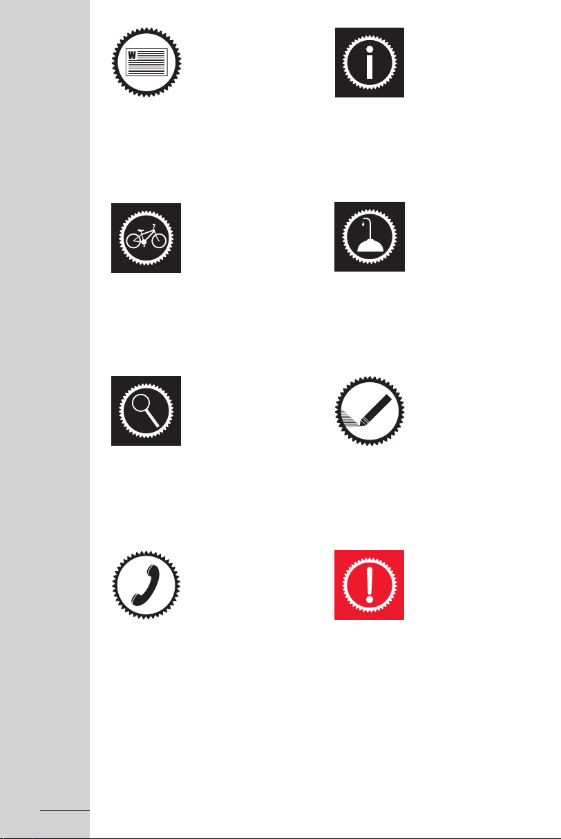
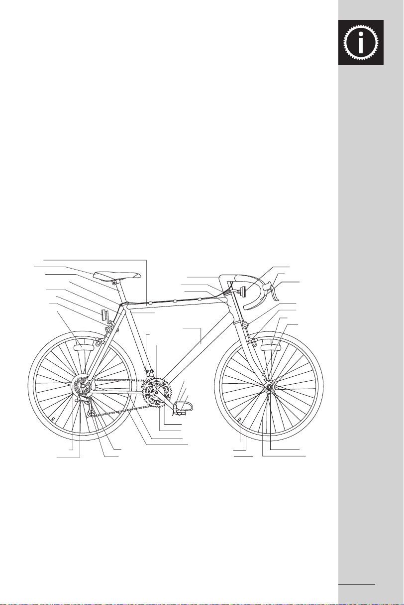
Finding the bicycle to best suit your needs is made easy by the vast array of bicycle
Top Tube
Seat
Seat Post
Seat Post Binder Bolt
Seat Stay
Rear Reflector
Rear Brake
Wheel Reflector
Freewheel
Gear Control Cable
Rear Derailleur
Handlebar Stem
Head Set
Head Tube
Seat Tube
Down Tube
Front Derailleur
Rear Gear
Control Cable
Pedal
Crank Arm
Chainwheel
Chainstay
Chain
Tyre Valve
Rim
Tyre
Shift Lever
Brake Lever
Handlebar
Brake Control Cables
Front Reflector
Front Brake
Wheel Reflector
Front Fork
Front Hub
Spokes
models and sizes available. Refer to the following diagrams to familiarize yourself with
the names of the various parts on your bicycle.
Mountain Bikes & Crossbikes.
Mountain bikes are one of the most versatile bicycles. Wider wheel rims and tyres ensure
maximum comfort and traction over a wider variety of surfaces and the frame and forks
are strong, making them particularly suitable for rough terrain. Manoeuvring is made
easier by the wider handlebars and convenient shift lever position. The Crossbike or
hybrid blends features of the mountain and racing bicycles. Its frame is lighter than
a mountain bike but heavier than a racing bicycle, providing stability and comfort with
increased speed.
4
PART 2 - PARTS IDENTIFACATION
Updated 23/05/07RAOM0507 Apollo Bicycle Company Pty. Ltd. ABN: 60 001 914 469
Page 7
Suspension Bikes.
Seat
Seat Post
Seat Tube
Seat Post Binder Bolt
Rear Reflector
Brake Control Cable
Gear Conrol Cable
Rear Suspension Damper
Rear Brake
Wheel Reflector
Gear Control Cable
Freewheel
Rear Derailleur
Pedal
Crank Arm
Bottom Bracket Axle
Chainwheel
Chainstay
Drive Chain
Tyre Valve
Rim
Tyre
Shift Lever
Brake Lever
Control Cables
Reflector
Upper Fork (Suspension)
Protective Boot
Fork Brace
Front Brake
Lower Fork (Suspension)
Front Hub Axle
Spokes
Handlebar
Handlebar Stem
Head Seat
Top Tube
Front Derailleur
Down Tube
Suspension Mounting
Head Tube
Rear Frame Sub Assembly
Suspension bicycles aim to maximize comfort and traction over rough terrain. The basis
of the mountain bike frame is blended with suspension – either suspension front forks only
or in combination with a rear suspension mechanism built into the frame. A special shock
absorbing seat pillar may also be present for improved rider comfort. Despite the variety
of suspension bikes available the basic components are similar in all models, such as
wide rims and tyres for increased traction and comfort.
Updated 23/05/07 RAOM0507 Apollo Bicycle Company Pty. Ltd. ABN: 60 001 914 469
5
Page 8
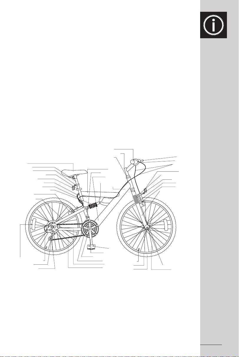
BMX Bicycles.
Top Tube
Seat
Seat Post
Seat Post Binder Bolt
Seat Stay
Rear Reflector
Wheel Reflector
Rear Sprocket
Training Wheel
Crash Pad
Handlebar Stem
Head Set
Head Tube
Chainwheel
Chainstay
Chain
Tyre Valve
Rim
Tyre
Handlebar Grip
Brake Lever
Handlebar
Brake Control Cable
Reflector
Front Brake
Brake Pad
Front Fork
Wheel Reflector
Front Hub
Spokes
Chain Guard
Crank Arm
Pedal
Crash Pad
Seat Tube
Down Tube
BMX style bicycles are ideal for young riders. Their durable, simple design makes them
perfect for general purpose use with minimal maintenance required. Alternative frame
styles, such as U-shape frames and loop frames, may also be used for other varieties
of children’s bicycles.
6
Updated 23/05/07RAOM0507 Apollo Bicycle Company Pty. Ltd. ABN: 60 001 914 469
Page 9
Road Bicycles.
Top Tube
Seat
Seat Post
Seat Post Binder Bolt
Seat Stay
Rear Reflector
Rear Brake
Wheel Reflector
Spoke Protector Disc.
Rear Derailleur
Freewheel
Rear Dropout
Handlebar Stem
Head Set
Head Tube
Seat Tube
Down Tube
Front Derailleur
Bottom Bracket Axle
Toe Strap
Toe Clip
Pedal
Crank Arm
Chainwheel
Chainstay
Chain
Ty re Valve
Rim
Tyre
Brake Control Cable
Front Reflector
Brake/Shift Lever
Handlebar
Front Brake
Brake Pad
Wheel Reflector
Front Fork
Front Hub
Spokes
Road or racing bikes aim to cater for fast travel over long distances on smooth surfaces.
Frames are light weight and rims have a narrower profile, for maximum efficiency and
speed.
Updated 23/05/07 RAOM0507 Apollo Bicycle Company Pty. Ltd. ABN: 60 001 914 469
7
Page 10

PART 3 - BEFORE YOU RIDE
FRAME SIZE
Choosing the appropriate frame and wheel size
is imperative when purchasing a new bicycle.
For safe riding the size of your bicycle should
properly match your build. In the case of children,
a bike should never be bought with aim of
“growing into it”. Riding the appropriate sized
bicycle enables the child to develop confidence,
as they have the necessary co-ordination to control
the bicycle. To accommodate the vast array of
height and size variables in children, even within
the same age groups, juvenile bicycles come in
different wheel sizes and frame styles to best suit
the rider’s size.
Ladies and gents’ bicycles are also available in
a variety of frame sizes. Sizing is based on the
distance between the centre of the bottom bracket
and the top of the frame seat tube.
Female riders should take into account the slope
of the top tube to determine frame size suitability.
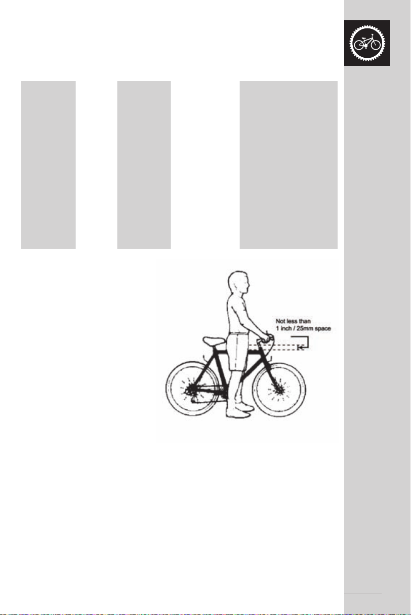
WARNING:
For safe riding your bicycle should
match your size correctly, otherwise
you may loose control and fall. Ideally
there should be a minimum clearance
of 25mm between the crotch of the
intended rider and the top frame tube
of the bike, while the rider straddles the
bicycle with both feet flat on the ground.
Clearance over the top of the frame ensures that
the rider can safely stand astride the bike when
forced out of the saddle, such as stopping at
traffic lights. Clearance heights vary according
to rider preference and between the different
bicycle models.
8
Updated 23/05/07RAOM0507 Apollo Bicycle Company Pty. Ltd. ABN: 60 001 914 469
Page 11
Please refer to the chart below to assist you in making the correct choice.
If you have any queries refer to your dealer.
Bicycling Sizing Guide
Approx.
Ages
Wheel
Size (kid’s
models)
Suggested
Frame Size for
Road Bikes
Suggested Frame Size
for Mountain or Hybrid
Bikes
4-6 30cm(12”) - 46cm min. 5-10 40cm(16”) - 55cm min. 6-14 50cm(20”) - 61cm min. 12-16 61cm(24”) - 61-69cm 12 plus - - 37cm(14.5”)
66-76cm 12 plus - - 43cm(17”)
71-79cm 12 plus - 50cm(19.5”) 45cm(18”)
12 plus - 55cm(21.5”) 50cm(19.5”)
79-86cm 12 plus - 57cm(22.5”) 52cm(20.5”)
81-89cm 12 plus - 60cm(23.5”) 53cm(21”) - 56cm(22”)
12 plus - 63cm(25”) 58cm(23”) - 60cm(23.5”)
Updated 23/05/07 RAOM0507 Apollo Bicycle Company Pty. Ltd. ABN: 60 001 914 469
9
Page 12
RIDING POSITION
Arms not over exteneded
Handlebar stem height
about the same as seat height
Pedal at bottom position
1. Saddle Height
To ensure pedalling efficiency, safety and rider
comfort it is crucial that the seat is set at the correct
height. The rider’s leg length is used to determine
the appropriate saddle position. When the seat is
positioned correctly the rider’s leg should not strain
from over-extension and the hips should remain
level when pedalling. To establish seat height sit
on the bicycle with one pedal at its lowest point,
and place the ball of the foot on that pedal.
If the knee is slightly bent in this position then the
seat is at its correct height. The leg should be
practically straight when the heel of that foot is
placed on the pedal.
Caution:
Ensure the seat pillar post does not
extend beyond the minimum insertion
mark. (Refer to Page 42 on how to
adjust the seat height). Take special
note if your bicycle is fitted with a
suspension type seat post.
10
2. Reach
When riding it is important not to overextend one’s
reach. To determine the ideal positioning place
your elbow against the seat and stretch out your
arm toward the handlebars. The distance between
the handlebar and the outstretched fingertips of the
arm should be 20mm – 50mm. This distance can
be adjusted by altering the location of the seat in
relation to the seat pillar. (Refer to Part 5 on how
to adjust the seat clamp)
Updated 23/05/07RAOM0507 Apollo Bicycle Company Pty. Ltd. ABN: 60 001 914 469
Page 13
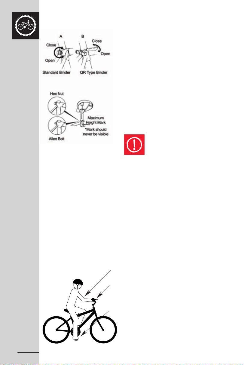
3. Handlebar Height
Handlebar Binder Bolt
Stem Wedge Bolt
Maximum Height/
Minimum Insertion Mark
Exceeds 2 1/2" (64mm)
It is recommended you try various handlebar heights to find the most suitable position
for you. Usually it is most comfortable when the handlebar height is the same as the
height of the seat. The handlebar stems of some bikes can be altered to customize
fit even further.
Caution:
Ensure the handlebar’s stem does not extend beyond the minimum
insertion mark. (Refer to Part 5 on how to adjust Handlebars).
WARNING:
The steering action may be compromised if the stem binder bolt, the
handlebar binder bolt or the bar end extension clamping bolts are not
sufficiently tightened. This could result in the rider losing control and falling.
To check, try to twist the handlebar/stem assembly whilst the front wheel
of the bike is positioned between your legs. If the stem twists in relation
to the front wheel, the handlebars turn relative to the stem, or the bar end
extension rotates in relation to the handlebar, the bolts need
to be tightened.
Updated 23/05/07 RAOM0507 Apollo Bicycle Company Pty. Ltd. ABN: 60 001 914 469
11
Page 14

SAFETY CHECKLIST
Safety checks are an important part of any ride. In conjunction with the
recommended maintenance in Parts 4 and 5 of this manual it is also
suggested that a thorough inspection should be undertaken fortnightly,
tightening all nuts and bolts, replacing worn and damaged parts and ensuring
all components are in their correct positions. For further details please refer
to Parts 5 and 6.
WARNING:
Body parts and other objects should be kept clear from the moving
components of the bicycle when in use, such as the spinning wheels and the
moving chain. When riding always wear appropriate footwear – i.e. shoes
that will grip the pedals and no sandals. Refrain from jumping with your
bike. Jumping puts enormous stress on many components of your bicycle,
especially your front fork.
Prior to every ride please complete the following safety checks.
1. Brakes
- Check front and rear brakes are working correctly
- Check brake control cables for wear and ensure they are oiled
and properly adjusted
- Check brake control levers are lubricated and securely fastened
to the handlebar.
- Check brake shoe pads for wear and their positioning in relation to the rims
2. Wheels and Tyres
- Check tyre pressure is as recommended according to the specification
displayed on the tyre sidewall
- Check tyres for tread and ensure they do not have any bulges
or excessive wear.
- Check all wheel spokes are firm and are intact
- Check rims run true and are without any obvious buckles or kinks
- Check that axle nuts are tight. For bicycles equipped with quick release
axles, ensure locking levers are tensioned appropriately and in the
closed position.
3. Saddle
- Check the clamp underneath the saddle is firmly secured
to the saddle post
- Check frame clamping mechanism is tightly fastened
- Ensure that the minimum insertion mark cannot be seen on the saddle pillar
12
Updated 23/05/07RAOM0507 Apollo Bicycle Company Pty. Ltd. ABN: 60 001 914 469
Page 15
4. Steering
- Check that the handlebar and stem enable correct steering
and are properly adjusted and tightened
- Check that the setting of the handlebars is correct in relation to the forks
and the direction of travel
- Check the head set locking mechanism is appropriately fixed and fastened
- If handlebar extensions are fitted check they are positioned
and secured correctly
- Ensure the minimum insertion mark cannot be seen on the handlebar stem
- Ensure the ends of the handlebars and bar ends are covered or capped.
5. Chain
- Check the chain is lubricated, clean and runs freely
- In wet or dusty conditions service the chain more frequently
6. Bearings
- Check headset, wheel bearings, pedal bearings and bottom
bracket bearings
- Check all bearings are oiled, run smoothly and show no signs of excess
movement, grinding or rattling
7. Cranks and Pedals
- Check cranks are securely fastened to the axle and are straight
- Check pedals are properly and firmly attached to the crank
8. Derailleurs
- Check the front and rear mechanisms are operating appropriately
- Check control levers are securely anchored
- Check derailleurs, control cables and shift levers are sufficiently lubricated
- If the gear components come with a separate, specific manual, refer to this
for further information
9. Frame and fork
- Check that the frame and fork are straight and intact.
- Replace if either is bent or broken.
10. Suspension (if applicable)
- Check that components operate smoothly with no binding. Keep clean
of grit, and lubricate top of outer leg seal.
- Check that all components of the fork & rear suspension
are properly tightened
- Check the rear suspension components for excessive wear or side play
- If the suspension components come with a separate, specific manual, refer
to this for more in depth information
Updated 23/05/07 RAOM0507 Apollo Bicycle Company Pty. Ltd. ABN: 60 001 914 469
13
Page 16
11. Safety & Accessories
- Check that all reflectors are attached correctly
and visible
- For riding at night, fit fully functioning dynamo
or battery powered lights
- Check that the bell is fully operational
- Check all additional components on the bike
are appropriately secured and functioning
- Ensure the bicycle rider and any passenger
in a child seat are wearing helmets
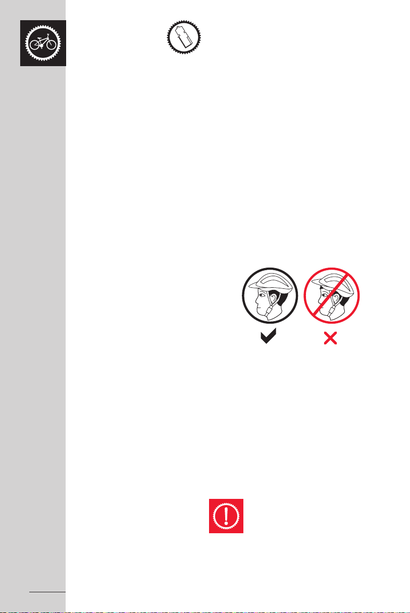
HELMETS
When riding your bicycle it is recommended that
you always wear an appropriately fitting, Australian
Standards Approved bicycle helmet. This also
applies to any passengers you may carry in a child
safety seat.
14
A bicycle helmet must:
- carry the Australia & New Zealand Standards
approved mark AS/NZS 2063 label
- fit properly
The helmet should be:
- well ventilated
- comfortable
- lightweight
The wearing of helmets is mandatory
in most Australian states. Non-
compliance may result in an
enforceable penalty.
Updated 23/05/07RAOM0507 Apollo Bicycle Company Pty. Ltd. ABN: 60 001 914 469
Page 17
RIDING SAFELY
General Rules
- The same road rules used for vehicles apply to
cyclists. Obey the road rules at all times, such
as giving way to pedestrians, and stopping
at red traffic signals
- Notify the Road Traffic Authority in your state if further
information is required.
- Ride on the left side of the road and never against
the traffic.
- Take extra care when attempting to overtake other
vehicles and at intersections.
- Indicate intended actions, such as turning or
stopping, by using appropriate hand signals.
- Ride predictably and in a straight line.
- Always ride defensively. You may be difficult to see
to other road users.
- Closely observe the riding terrain. Avoid obstacles
such as pot holes, gravel, wet road markings, oil,
curbs, speed humps and drain grates.
- Be alert. Watch for such things as motorists opening
doors or backing out of concealed driveways.
- Sound your bell for a warning when required.
- Train and tram tracks should be crossed at a
90 degree and preferably walk your bicycle over.
- Know how your bicycle operates. Practice braking,
gear shifts and if fitted, using toe clips and straps.
- Always apply the rear brake first, then the front when
braking. The front brake is more potent and if it is not
used properly you may loose control and fall.
- Allow reasonable space between yourself and other
vehicles and objects when riding and stopping.
Take note of weather conditions and its possible
impact on safe braking distances. e.g.. Wet riding
surfaces increase braking distances.
- Use leg clips or elastic bands if you are wearing
loose trousers to stop them catching in the chain.
- Ensure your vision or control of the bicycle is not
obstructed by any items you may be transporting.
- Do not use items that may impede your hearing.
e.g. Headphones
Updated 23/05/07 RAOM0507 Apollo Bicycle Company Pty. Ltd. ABN: 60 001 914 469
15
Page 18

Wet Weather
- Ride more cautiously in wet weather.
Avoid sudden braking, slow overall riding pace
and approach corners more carefully.
- Brake sooner, stopping distance increases
in wet conditions.
- Remember pot holes and slippery surfaces
such as line markings and tram tracks all
become more hazardous in the wet.
Try to avoid where possible.
- Cornering traction will also be reduced in wet
weather.
Night Riding
- Wear reflective and light coloured clothing.
- Reflectors should be fitted correctly to the
bicycle and clearly visible. (Refer to Part 5
of this manual.)
Riding in the dark should never be
undertaken without fully operational
front and rear bicycle lights. The use
of bicycle lights is mandatory for night
riding in most Australian States.
- Attach a fully operational lighting set.
Lights should have a white front lamp
and a red rear lamp.
- Use a flashing rear light to improve visibility.
- Charge batteries if battery powered lights
are to be used. Check wiring connections
for dynamo powered lights.
- Avoid riding at night if possible. If not, slow
down and opt for familiar roads with street
lighting when able.
16
Pedalling Technique
- Place the ball of your foot on the centre
of the pedal.
- Ensure your knees are parallel to the bicycle
frame when pedalling.
- Keep your elbows slightly bent. This will help
to absorb shock.
- Learn how to use the gears correctly (Refer
to Pages 18-21 in this part of the manual).
Updated 23/05/07RAOM0507 Apollo Bicycle Company Pty. Ltd. ABN: 60 001 914 469
Page 19

Hill Technique
- Prior to a climb, gear down and continue gearing down as necessary in order to sustain
pedalling speed.
- By standing up on your pedals you will be able to generate greater power from each turn
of the pedal. This is useful if you are straining and are using the lowest gear.
- Use the high gears on a descent to prevent rapid pedalling.
- Take extra care when descending. Do not exceed a comfortable speed
and maintain control.
WARNING:
Downhill mountain biking can be a dangerous activity. To reduce the likelihood
of injury appropriate safety equipment should be worn and ensure that your
bike is working perfectly. Follow all of the above instructions.
Cornering Technique
- Before entering a corner brake slightly and begin to lean your body into the corner.
- The inside pedal should be held at the 12 o’clock position and the inside knee angled
slightly in the direction you are turning. The other leg should be kept straight.
- Avoid pedalling through fast or tight corners.
Rules for Children
Any child bicycle rider needs to be taught correct riding skills and behaviour, particularly
addressing safety, before they take to the streets. Hopefully by doing so accidents can
be avoided.
1. Always wear a correct fitting helmet
2. Follow all road rules, especially stop signs and red lights
3. Always proceed with caution before entering a street. Only enter if there
is no traffic approaching.
4. Avoid riding on driveways or the road
5. Do not ride on busy streets
6. Be conscious of other road vehicles in the vicinity
7. Avoid night riding
8. Take extra care when riding downhill. Slow down using the brakes and maintain
control of the steering
As suggested by the Consumer Affairs Department riding bicycles with small
wheel diameter at excessive speeds can lead to instability and is therefore not
recommended.
Caution:
When riding downhill never take your hands off the handlebars,
or feet off the pedals.
Updated 23/05/07 RAOM0507 Apollo Bicycle Company Pty. Ltd. ABN: 60 001 914 469
17
Page 20

GEARS: HOW TO OPERATE
Derailleur Gears
Derailleur gears are the most common type
of gear systems used on bicycles. They are the
changing mechanism used to move the drive chain
up and down a series of cogs or sprockets
(the cluster or cassette stack) at the rear of the
bicycle and across the chainwheel at the front
of the bike (if fitted). Multispeed bicycles today
can range form 5-6 gears to as many as 30.
Rear derailleurs are fitted to all multispeed bicycles
while front derailleurs are only present on those
bicycles with the higher number of gears.
Gears enable the cyclist to select the most
appropriate pedalling resistance best suited
for the riding conditions. The more gears fitted
to the bicycle the greater choice available
to the rider.
TYPES OF GEAR SHIFTERS
- Hand Grip Shifters
- Below Bar Shifters
- Dual Control Shifters
18
Updated 23/05/07RAOM0507 Apollo Bicycle Company Pty. Ltd. ABN: 60 001 914 469
Page 21
Operating Principles
1
2
3
4
5
6
a
b
c
1
High
2
Medium
3
Low
1
2
3
4
5
6
a
b
1
High2Medium
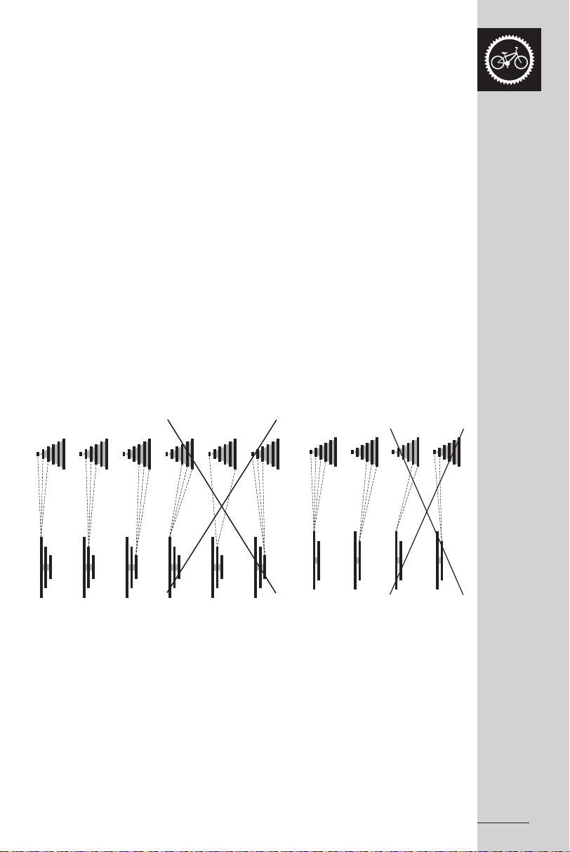
Although the number of gears present on
multispeed bicycles varies greatly, how the gears
function remains the same. The right shifter
works the rear derailleur and the left shifter works
the front derailleur. If the pedals are stationary
or rotating backwards, gears cannot be changed.
They can only be altered when pedalling forward.
To achieve a successful gear change, either
moving up or down in gears, the pedalling
pressure must be relaxed. Failure to ease the
pressure when changing gears may result in
bicycle damage or could even cause the rider
to lose control. If a rubbing sound is detected
after attempting to alter gears, adjust the shifter
until the sound ceases. Generally the lower
gears are for ascending hills and the higher gears
are for descending. To extend the life of your
chain avoid using extreme gear combinations
as shown in the diagrams below.
Recommended Chainwheel/Rear Sprocket Gear Combinations
Updated 23/05/07 RAOM0507 Apollo Bicycle Company Pty. Ltd. ABN: 60 001 914 469
19
Page 22
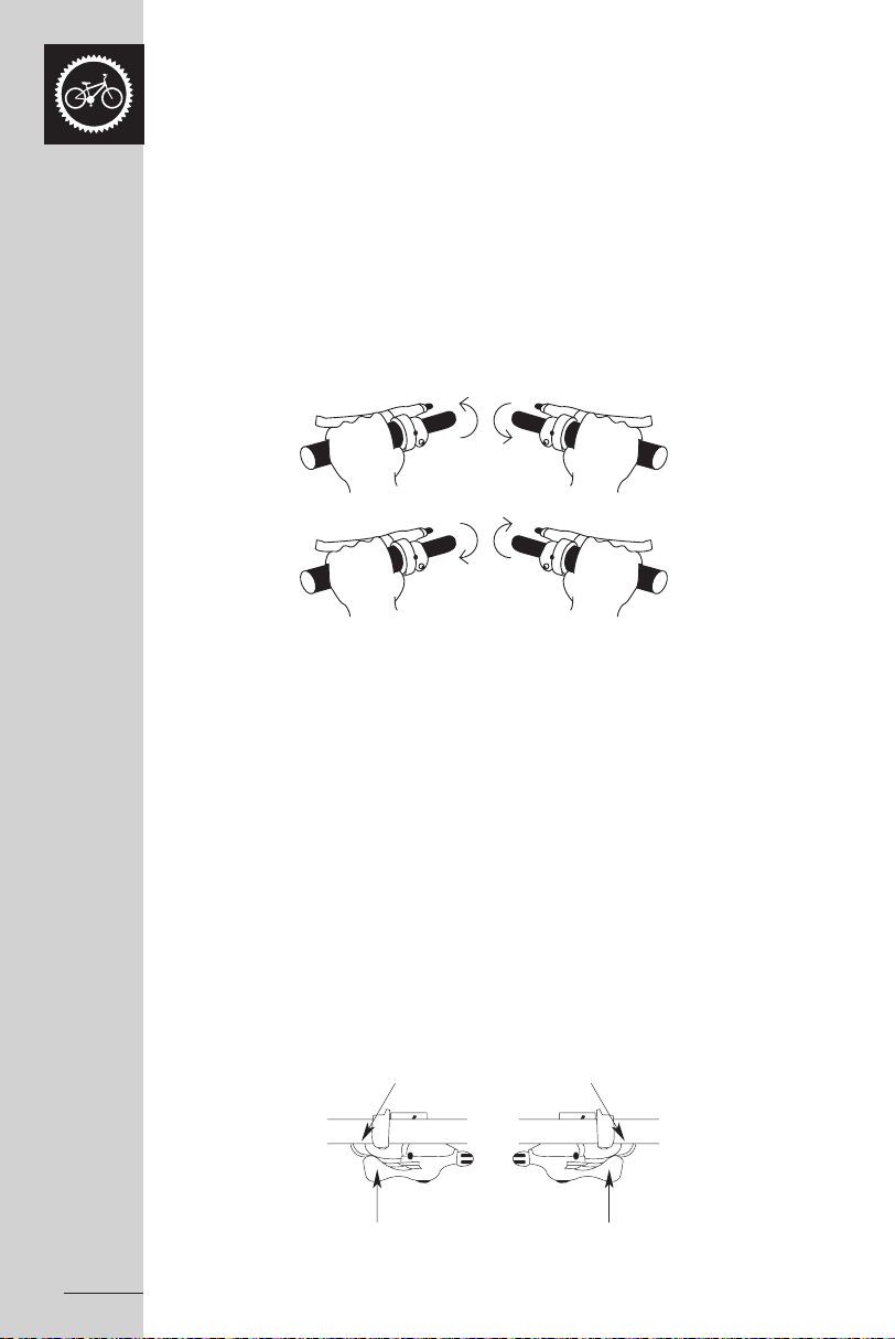
Hand Grip Shifters
Left
Low gear front
Right
High gear rear
High gear front Low gear rear
Front Low Gear Rear Low Gear
Front High Gear Rear High Gear
L H H L
Left
Low gear front
Right
High gear rear
High gear front Low gear rear
L H H L
Hand grip shifters are built into the hand grip and attach to the handlebars. Unlike other
types of shifting mechanisms the hand grip shifters mean you do not need to change your
hand position to select different gears. The rider just simply twists forwards or backwards
dependent upon their gear selection. By twisting the right shifter toward you, a lower gear
is chosen as a larger rear cog is selected. Twisting this shifter away from you has the
opposite effect; a higher gear is selected as a smaller rear cog is engaged. Turning the
left shifter forward or away from you activates a smaller, front chainwheel, and a larger,
front chainwheel is engaged by twisting it backwards. The number of gear changes
to occur at any one time corresponds with how many turns are made of the shifter.
Check the diagram below for operating instructions.
Below the Bar Shifters
The majority of mountain style bicycles use below bar shifters. These shifters are mounted
on the underside of the handlebars, usually between the grips and the handlebars.
It is a two finger operating system which uses the thumb and index finger to make the
gear selection. By pushing the lower (larger) right shifter with your thumb, a lower gear
is selected as a larger, rear cog is engaged. One cog can be selected through one firm
push, or by continuing to push on the lever multiple cogs can be engaged. By pushing
the upper (smaller) lever on the left inwards with your index finger, the chain moves to a
smaller chainring. A higher gear can be selected by pushing the upper right lever with
your index finger to activate a smaller rear cog. By pushing the lower left lever with your
thumb the chain will move from the smaller to the larger chainring. To clarify please refer
to the following diagram.
20
Updated 23/05/07RAOM0507 Apollo Bicycle Company Pty. Ltd. ABN: 60 001 914 469
Page 23

Dual Control Shifters
High Gear
Rear
Low Gear
Rear
Low Gear
Front
High Gear
Front
Rapid Fire Shifters
The majority of drop bar road bicycles produced today are fitted with dual control levers.
Since both the brakes and the gears are built into the one mechanism, dual control
shifters make it possible to change gears without having to remove your hands from the
handlebars. Shifting can be performed whilst your hands are resting on the lower bend
of the handlebars or on the brake lever hoods (in the “drops”). Pulling the shifter towards
the bar activates the brakes, while shifting the dual control lever in towards the front wheel
engages the gears. To select a higher gear, the small right lever is pushed to engage
a smaller, rear cog. Pushing the large lever inwards activates the large, front chainwheel.
To select a lower gear, shift the large right lever inward to engage a larger rear cog.
One firm push shifts the chain one cog, while continuing to press will move the chain
over multiple cogs.
Updated 23/05/07 RAOM0507 Apollo Bicycle Company Pty. Ltd. ABN: 60 001 914 469
21
Page 24

BICYCLE CARE
Basic maintenance
To keep your bicycle in prime condition follow the recommendations listed below.
Painted frames should be dusted and any loose dirt dislodged with a dry cloth. Clean
by wiping with a damp cloth soaked in a mild detergent mixture. Use a cloth to dry and
polish with car or furniture wax. Plastic parts and rubber tyres should be cleaned with
soap and water. Wipe a rust preventative fluid over chrome plated bikes.
All moving parts should be habitually cleaned and lubricated, and components secured
and adjusted as needed. (Refer to Parts 4 and 5 of this manual for further details)
Apply touch up paint or clear nail varnish to any areas where the paint has become
scratched or clipped to the metal. This will help prevent rusting.
The potential for rusting is limited by the use of alloy components and B.E.D
(black electronic deposit) treated steel rims.
To avoid rapid bearing deterioration the hub and bottom bracket bearings need
to be removed and re-greased if the bicycle has been submerged in water.
Avoid cycling in the rain or exposure to corrosive materials, such as the salt from riding
on the beach, as much as possible. If unavoidable, wash and dry your bicycle often
and wipe or spray all unpainted parts with an anti-rust treatment. Dry the wheel rims
so braking performance is not hindered.
Storage
Protect your bicycle from the elements by storing it in a dry, shady location.
Prolonged ultra violet light exposure may cause the paint to fade or the rubber
and plastic parts to crack.
The bicycle should be cleaned, lubricated and the frame waxed if it is to be stored for any
length of time. Deflate the tyres to half pressure and hang the bicycle off the ground.
PART 4 - BICYCLE CARE & SERVICING
Store away from electric motors as ozone emissions may damage the rubber and paint.
Do not cover with plastic as rusting may occur due to “sweating.”
22
Updated 23/05/07RAOM0507 Apollo Bicycle Company Pty. Ltd. ABN: 60 001 914 469
Page 25

Security
Solid Post
Bicycle Frame
U - Lock
Rear Wheel
High Security using a U - Lock
In an attempt to prevent your bicycle from being stolen the following precautions should
be undertaken.
1. Take note of the bicycle serial number, generally located underneath the bottom bracket
of the frame.
2. Register the bicycle with the manufacturer/distributor and local police
3. If your bicycle is left unattended, always secure it to an immovable object, such
as a lamp post. Use a high quality bicycle lock that will resist hack saws
and bolt cutters.
Updated 23/05/07 RAOM0507 Apollo Bicycle Company Pty. Ltd. ABN: 60 001 914 469
23
Page 26

Regular and proper upkeep of your new bike means:
• Smooth Running
• Longer lasting components
• Safer Riding
• Cost savings
Routine bicycle maintenance is an essential component of riding. The condition of your
bicycle changes every time it is used, meaning more frequent maintenance is necessary
the more you ride your bicycle. The tables listed below outline the recommendations for
servicing your bicycle. By referring to these and the information in Part 5 of this manual,
you should be able to complete most of your bicycle maintenance yourself.
Contact your specialist bicycle dealer if you require further assistance.
Schedule 1 – Lubrication
Frequency Component Lubricate How to Lubricate
Weekly Chain chain lube or light oil brush on or squirt
Derailleur wheels lube or light oil brush on or squirt
Derailleurs oil oil can
Brake callipers oil 3 drops form oil can
Brake levers oil 2 drops from oil can
Monthly Shift levers lithium based grease disassemble
Brake cable ends oil 1 drop from oil can
6 monthly Hubs lithium based grease disassemble
Bottom bracket lithium based grease disassemble
Pedals lithium based grease disassemble
Freewheel oil 2 squirts form oil can
Brake cables lithium based grease disassemble
Derailleur cables lithium based grease disassemble
Yearly Wheels bearings lithium based grease disassemble
Headset lithium based grease disassemble
Seat pillar lithium based grease disassemble
24
Note: Increase the regularity of maintenance the more you ride and use in wet
or dusty conditions.
Take care not to over lubricate – excess lubricant should be removed to prohibit dirt build up.
WARNING:
Always seek expert advice for any maintenance requirements you feel unable
to complete. You run the risk of potentially damaging your bicycle or yourself
from falling if your bike is not correctly serviced or adjusted.
Updated 23/05/07RAOM0507 Apollo Bicycle Company Pty. Ltd. ABN: 60 001 914 469
Page 27

Schedule 2 – Service Checklist
Frequency Task Page Reference
Before every ride Check tyre pressure 28
Check brake operation 43
Check wheels for loose spokes 27
Make sure nothing is loose 26
After every ride Quick wipe down with damp cloth 22
Weekly Lubrication as per schedule 1 24
Monthly Lubrication as per schedule 1 24
Check derailleur adjustment 61
Check brake adjustment 44
Check brake and gear cable adjustment 44, 61
Check tyre wear and pressure 28
Check wheel are true and spokes tight 27
Check hub, head set and crank bearings
32, 38, 52
for looseness
Check pedals are tight 51
Check handlebars are tight 36
Check seat and seat post are tight
41
and comfortably adjusted
Check all nuts and bolts are tight 26
6 monthly Lubrication as per schedule 1 24
Check all points as per monthly service 25
Check and replace brake pads if required 48
Check chain for excess play or wear 56
Yearly Lubrication as per schedule 1 24
WARNING:
All components of the bicycle are subjected to wear and stress through use.
Watch closely for any scratches, cracks or discolouration on your bicycle
components. These are signs of a stress-caused fatigue and indicate that
a part needs to be replaced. Failure to replace can cause the component
to suddenly fail when riding, which may result in serious injury or even death.
Updated 23/05/07 RAOM0507 Apollo Bicycle Company Pty. Ltd. ABN: 60 001 914 469
25
Page 28

Torque requirements
Nuts and bolts should only be adjusted using a torque wrench. This helps to prevent over
tightening and damage to the threads. Different torque measurements are recommended
when tightening different components. Use the following table to guide you in your torque
application.
Component Torque
Front axle nuts 22 – 27 Nm
Rear axle nuts 24 – 29 Nm
Handlebar clamp nut 17 – 19 Nm
Head stem expander bolt 17 - 19 Nm
Seat clamp nuts 12 – 17 Nm
Seat post binder nut 15 – 19 Nm
Brake cable fixing nut 7 – 11 Nm
Brake calliper centre bolt nut 1 2 – 17 Nm
Cotterless crank nut 27 Nm
Tools needed for making adjustments:
1. Adjustable wrench
2. Flathead screwdriver
3. Allen key wrenches: 2mm, 3mm, 4mm, 5mm,
6mm, 8mm
4. Tyre pump
5. Standard multi – grip pliers
6. Phillips head screwdriver
7. Open ended or ring spanners: 8mm, 9mm,
10mm, 12mm, 13mm, 14mm, 15mm
8. Torque wrench with Newton Meter increments
9. Tyre levers
10. Crank remover
11. Tube repair kit
26
Updated 23/05/07RAOM0507 Apollo Bicycle Company Pty. Ltd. ABN: 60 001 914 469
Page 29

WHEELS AND TYRES
Wheels Inspection
Maintaining your wheels in prime condition is imperative for not only for riding efficiency
and performance, but safety as well. When inspecting your wheels look for the potential
hazards listed below.
Quick release: Caution: Quick release skewer levers should always read “closed”.
Prior to each ride check that these are set to the closed position and are at the correct
tension. Serious injury may result if these guidelines are not observed.
Axle nuts: Caution: Do not ride the bicycle without first ensuring that the axle nuts are tight.
Buckled Wheels: Prior to each ride test each wheel to ensure that it is spinning straight.
If the wheels are misaligned adjustment will be necessary. We recommend any
adjustments should be completed by a professional bicycle mechanic as it is quite
a complex task. In the case of buckled wheels that use rim brakes, braking
is adversely effected.
Broken or loose spokes: Caution: Damaged spokes can create severe instability and
have the potential to cause an accident for the rider. Before riding ensure that all spokes
are present, intact and are taut. Spoke repairs can be difficult and are best undertaken
by a professional bicycle mechanic.
Loose hub bearings: Caution: Do not ride your bicycle if the hub bearings are loose
or damaged. Check the hubs by moving the wheel from side to side. If movement
is detected adjustments will be needed.
PART 5 - COMPREHENSIVE MAINTENANCE
Rims: Brakes can become ineffective if dirt or grease accumulate on the rims.
Check that your rims are clean and dry before using. Take care to prevent oil contact
on the rim braking surfaces when lubricating your bicycle.
Updated 23/05/07 RAOM0507 Apollo Bicycle Company Pty. Ltd. ABN: 60 001 914 469
27
Page 30

Tyre inspection
As tyres are the rider’s only contact with the road, correct tyre maintenance is crucial
for stability and safety. Consider the following when inspecting your tyres:
Tread: Check the tread for signs of excessive wear or flat spots, and cuts or damage.
Caution: Riding on excessively worn or damaged tyres may be hazardous so tyres should
be replaced.
Inflation: Maintain tyre pressure at the level recommended on the tyre sidewalls.
Preferably use a tyre gauge and a hand pump to inflate rather than a service station pump.
Caution: Using a service station pump for inflation can lead to sudden over inflation,
potentially resulting in a blow out.
Valves: A flat tyre is not only inconvenient but potentially dangerous. To minimise the
likelihood of a flat tyre from air leaking from a valve, ensure valve caps are fitted and that
valves are clean.
Bead setting: Ensure the bead is correctly fitted in the rim when inflating or changing tyres.
Recommended Tyre Pressures:
Tyre pressure directly influences the performance of a tyre on different surfaces and in
varying weather conditions. Recommended tyre pressure is given either as maximum
pressure or as a pressure range.
For riding on smooth, slick terrain such as hard-packed clay and on deep, loose surfaces
such as deep, dry sand, tyres should be inflated to lower pressures, at the bottom of the
recommended pressure range. This helps to cushion the rider against the impact.
28
Using high pressures, at the top of the recommended pressure range enables a faster
but rougher ride. These pressures are ideal for riding on a smooth, dry pavement.
Failure to sufficiently inflate the tyres according to the rider’s weight and intended use can
cause the tube to puncture.
Tyres should be inflated to the recommended pressure moulded on the sidewall of
the bicycle’s tyres. Use this chart as a reference if you are unable to find the relevant
information on your tyre.
BMX 241 - 344 k.p.a. (35-50 p.s.i.)
MTB 276 - 448 k.p.a. (40-65 p.s.i.)
Road Touring 483 - 620 k.p.a. (35-50 p.s.i.)
Road Racing 755 - 862 k.p.a. (110-125 p.s.i.)
Hybrid/Crossbike 414 - 690 k.p.a. (60-100 p.s.i.)
Caution:
Service station pumps and pencil type automotive tyre gauges should not be
relied upon for consistent, accurate readings. A good quality dial gauge should
be used as it is far more accurate and reliable.
Updated 23/05/07RAOM0507 Apollo Bicycle Company Pty. Ltd. ABN: 60 001 914 469
Page 31

Front Wheel Removal
1. Open the brake quick release, if fitted, or screw
in the brake cable adjuster. You may need to undo
the brake cable anchor bolt if more clearance
is required.
2. Where standard axle nuts are present use a
spanner to loosen. If secondary retention devices
are fitted slacken the nuts enough to give clearance
to remove the wheel.
3. Turn the lever to the open position if a quick
release axle is fitted. Where the secondary
retention devices are fitted, the adjusting nut
at the opposite end to the Quick Release lever
needs to be loosened sufficiently to permit the
wheel to be removed.
4. Remove the wheel.
Front Wheel Replacement
1. Guide the wheel into the frame ensuring that the
axle fits well up against the fork slots. The fork
legs may need to be slightly prised apart.
2. If the wheel has a Quick Release axle, ensure the
quick release lever is open on the left side of the
bicycle. Check Quick Release tension and close
the lever when adequate tension is achieved.
When closed the lever should be parallel to the
fork to prevent accidental opening when riding.
3. When secondary retention devices are present,
ensure they are properly lodged in the fork ends.
4. If fitted, firmly fasten both axle nuts.
5. Re-set the brake quick-release and inspect the
brake pad clearance. If able, adjust the brake
cable/pad clearance.
WARNING:
The secondary retention device is crucial to safe riding. Tampering with
or removal of this device may cause serious injury or death. It may also
void your warranty.
CAUTION:
You need to ensure the tension of the quick release lever is sufficient. To tighten,
open the lever and turn the tension adjusting nut clockwise a quarter turn until you
can only fully close the quick release by wrapping your fingers around the fork for
leverage, and the lever leaves a clear imprint in the palm of your hand.
WARNING:
Quick release adjustments are still necessary even if secondary retention devices
are fitted. Failure to properly adjust the quick release mechanism may lead to
wheel instability, which ultimately could cause the rider to lose control and fall.
Updated 23/05/07 RAOM0507 Apollo Bicycle Company Pty. Ltd. ABN: 60 001 914 469
29
Page 32

Rear Wheel Removal
1. Open the brake quick release, if fitted, or screw in brake cable adjuster. Undo the
brake cable anchor bolt if greater clearance is required.
2. Move the chain onto the smallest rear cog if derailleur gears are fitted.
3. When the wheel is fitted with standard axle nuts, loosen them with a spanner.
4. Turn the quick release lever to the open position if a quick release axle is present.
5. Hold the derailleur unit and allow the wheel to slide forward out of the frame.
6. Rest the bike upside down on the handlebars and saddle. After wheel is removed,
do not rest bike on rear derailleur, as it may be damaged or misaligned as a result.
7. For single gear bicycles with a coaster hub, disengage the brake arm clip from the
brake arm, lift the chain off the rear cog and over the rear axle by hand, then allow
the wheel to slide out of the frame.
Rear Wheel Replacement
1. Wheel replacement virtually follows the reverse process to rear wheel removal
2. For derailleur geared bicycles, hold the rear derailleur spring fully back and feed
the top part of the smallest hub cog into the top part of the chain. Fit the wheel
into the frame.
3. For single geared bicycles, lift the chain over the axle and onto the cog, and fit the
wheel onto the frame.
4. Ensure the wheel is centred correctly in the frame and then firmly secure both axle
nuts. To test if the wheel is centred, inspect the distance between the front of the
wheel and the frame chainstay tubes on either side.
5. If the wheel has a Quick Release axle, the quick release lever needs to be open and on
the left side of the bicycle. Check the Quick Release tension and close the lever when
correct. For safety reasons the lever should be parallel to the frame seat stay tube.
6. On coaster hub bicycles, the brake arm needs to be reconnected to the brake arm clip
on the chainstay.
7. Reset the brake quick release and check the brake pad clearance. If required, adjust
the brake cable/pad clearance.
30
Caution:
Take care to correctly refit a rear wheel.
Failure to do so may be dangerous.
Updated 23/05/07RAOM0507 Apollo Bicycle Company Pty. Ltd. ABN: 60 001 914 469
Page 33

Correct Quick Release Axle Setting
The process of removing wheels is made considerably
easier if a Quick Release mechanism is fitted to the
wheel axle. Wheels can be removed without using
tools. The Quick Release mechanism consists
of a lever controlling a cam-action tightener and at
the other end a long bolt with an adjusting nut.
WARNING: It is crucial that the Quick
Release mechanism is properly adjusted
when riding. Failure to do so may cause
the wheel to wobble or disengage from the
bicycle, possibly resulting in harm to the
bicycle, and/or the rider.
Consequently:
1. Seek instruction from your bicycle
specialist on the correct process for
removing and installing Quick Release
wheels
2. Prior to riding your bicycle, ensure that
the wheel lever is firmly clamped.
To correctly clamp your quick release wheels in
place, refer to the following.
1. To set, open the lever so that the curved part faces
away from the bicycle.
2. While holding the lever in one hand, spin
the adjusting nut manually until it is tight.
3. Spin the lever halfway towards the closed position. Tighten the adjusting nut in a
clockwise direction until there is firm resistance to turning the lever beyond that point.
4. Pivot the lever all the way to the closed position so that the curved part of the lever
faces the bicycle.
5. When the jagged edges on the Quick Release clamping parts actually begin to cut into
the bicycle frame/fork surfaces the wheel is firmly secured.
6. To operate a Quick Release seat post binder mechanism follow the same process.
Updated 23/05/07 RAOM0507 Apollo Bicycle Company Pty. Ltd. ABN: 60 001 914 469
31
Page 34

Hub Bearing Adjustment
Cone Locknut
Hub Body
Axle
Washer
Axle Nut
Bearing Cone
Ball Bearings
The hub bearings of both wheels should be inspected for side movement.
Adjustment is required if there is any more than slight lateral movement.
To adjust:
1. Remove the wheel from the bicycle.
2. Use a flat, open ended cone spanner to hold the adjusting cone of the hub
and simultaneously loosen the hub’s locknut on the same side.
3. Turn the adjusting cone as required until there is minimal side play, and before binding
of the bearings occurs.
4. Hold the adjusting cone in position and secure the locknut.
5. Test that the wheel spins freely without excessive lateral movement, or binding
on the bearings.
32
Hub Lubrication
At least once a year your wheel bearings need to be disassembled and re-greased.
Riding in very muddy or wet conditions will mean more frequent servicing. Due to the
complexity of the task you may prefer to have a professional bicycle mechanic perform
the disassembly. However, if you feel capable the process is listed below:
1. Take the wheel out of the frame.
2. Remove the axle nut, cone lock nut, and the bearing cone from one side of the hub axle.
3. Remove the axle, complete with the cone and lock nut, from the other side of the hub.
4. If your bicycle is fitted with dust caps, carefully remove them from both sides of the
hub to expose the ball bearings.
5. If ball bearings and ball retainers are present, carefully remove these from both sides
of the hub.
6. Remove the freewheel on rear hubs with screw on type freewheels before
disassembling the axle. (You will need to use a special tool to do this.)
7. Clean all the hub components thoroughly and check for damage, especially looking
for pits or grazes in the bearing surfaces and cones, and damaged ball bearings.
Replace if required.
8. Insert grease into each clean or new ball bearing and into the inner cups of the hub,
and refit.
9. Re-assemble the hub axle in reverse sequence to disassembling, taking care
to properly re-adjust the bearing cones.
Updated 23/05/07RAOM0507 Apollo Bicycle Company Pty. Ltd. ABN: 60 001 914 469
Page 35

How To Repair A Flat Tyre
There comes a time when most cyclists will need to repair a flat
tyre. Use the following steps to guide you through the process:
1. Take the wheel off the bicycle.
2. Using the valve, entirely deflate the tyre.
3. Push the tyre bead inwards around the whole rim to loosen.
4. Using tyre levers only (to avoid damaging the rim), prise one
side of the tyre bead up over the edge of the rim.
5. Leave the tyre on the rim and remove the tube.
6. Replace or repair the tube. Note: The replacement tube
size needs to correspond with the size detailed on the
sidewall of the tyre and the valve type needs to be suitable
for your bicycle. Refer to the instructions in your tyre repair
kit to successfully patch a tube.
7. To determine the possible cause of the leak, match the
position of the puncture in the tube in relation to the tyre
and mark the location on the tyre.
8. Remove the tyre completely from the rim and examine,
removing any foreign objects noted, eg. glass or a nail.
Also inspect the inside of the rim for other potential causes,
such as protruding spokes. Replace the rim tape covering
the spoke ends, if damaged.
9. Remount the side of the tyre onto the rim.
10. Partially inflate the tube with a hand pump until it starts
to take shape.
11. Taking care not to twist the valve stem, place it through
the hole in the rim and work the tube into the tyre.
12. Starting either side of the valve use your hands to remount
the other side of the tyre by pushing the edge toward the
centre of the rim. Work around the rim until the tyre is almost
completely remounted.
13. Push the valve up into the rim and ensure that the tyre
sits properly in position.
14. Remount the remainder of the tyre by using your thumbs
to roll the last, most difficult, part on. Note: Do not use
tyre levers as these can easily puncture the tube
or damage the tyre.
15. Ensure that the tube is completely free of the rim
and the tyre bead at all points.
16. Inflate the tube with a hand pump until the tyre begins
to take shape, ensuring the tyre bead sits evenly around
the entire rim. Fully inflate the tyre to the pressure marked
on the sidewall when properly positioned. Check pressure
with a tyre air pressure gauge.
17. Replace the wheel into the frame and adjust gears, brakes
and quick release levers as necessary.
Updated 23/05/07 RAOM0507 Apollo Bicycle Company Pty. Ltd. ABN: 60 001 914 469
33
Page 36

Tyre Valves
Schraeder Valve
(Car/American)
Presta Valve
(French)
TM
Bicycles primarily use either Schraeder™ or Presta
tyre valves. To inflate tyres the pump needs to be
fitted with the appropriate attachment specific to
the valve stem.
The Schraeder™ valve is the most commonly
used tyre valve. It is also known as the car or
the American valve. Tyres fitted with Schraeder™
valves can be inflated using either a hand pump
or a service station pump, as it is the same valve
used on cars. Inflation involves removing the
valve dust cap, then screwing or pushing on the
pump connector to the end of the valve stem and
inflating. By depressing the pin in the end of the
valve stem the tyre can be deflated.
The Presta valve is also referred to as the French
or high pressure valve. In order to inflate tyres
equipped with this valve, the pump needs to have
a special fitting attached to accommodate the
valve’s narrower profile. The service station pump
can be used if an adapter is screwed onto the
valve stem. Inflation involves removing the dust
cap, unscrewing the valve stem locknut, freeing the
valve stem by pushing down on it, then fitting the
pump head and inflating. Deflation is achieved by
opening the valve stem locknut and depressing the
valve stem.
34
™ - Schraeder is a registered Trademark
of the Schraeder Corporation Inc.
Note: The valve dust cap should always be
replaced in order to prevent dirt entering and
damaging the valve.
Using a service station pump to inflate tyres is not
encouraged as tyres may blow out if sudden over
inflation occurs.
Updated 23/05/07RAOM0507 Apollo Bicycle Company Pty. Ltd. ABN: 60 001 914 469
Page 37

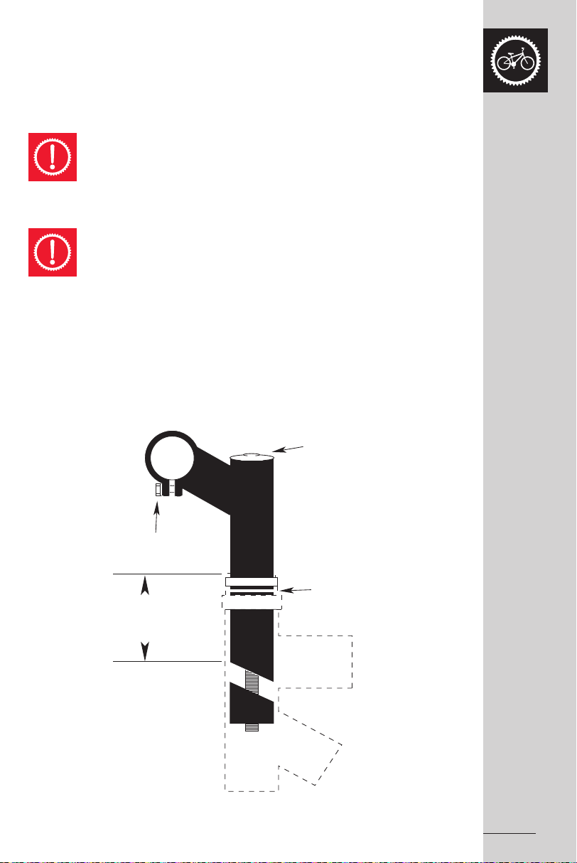
STEERING SYSTEM
Stem bolt
Handlebar Binder Bolt
Maximum Height/
Minimum Insertion Mark
Expander Bolt Wedge
MTB Handlebar Stem
Stem bolt
Handlebar Clamp Bolts
Maximum Height/
Minimum Insertion Mark
Expander Bolt Wedge
BMX Handlebar Stem
Stem Bolt
Head Set
Head Tube
Maximum Height/
Minimum Insertion Mark
Expander Bolt
Wedge
BMX Handlebar Assembly
Handlebar Stem
Usually the standard handlebar stem is secured
into the steering column by the binder bolt and
expander wedge. These bind with the inside of
the fork, steerer tube when tightened. The stem
may also clamp onto an unthreaded fork steerer,
as is the case with the 'Ahead Set' system.
Note: The handlebar height can be altered to suit
the rider’s preference.
To remove a standard stem, the expander bolt needs to be loosened two or three turns,
and then tapped to free the wedge inside. Servicing involves applying a thin film of grease
to the part after it has been wiped clean. Also lubricate the wedge that will be inserted into
the frame.
NOTE: These same adjusting principles cannot be applied to the ‘Ahead Set’
headstem system.
Etched on the stem is a mark about 65mm up from the bottom with the words
“max. height” or “minimum insertion”. Never ride a bicycle if the stem has been
raised so that the minimum insertion / max. height line can be seen.
The front brake cable is routed through a hole in the front of the stem on some MTB bikes.
Adjusting the height
on this type of stem
means you will
need to re-adjust
the front brake.
Check that the
suspension is intact
and operating
properly on bicycles
equipped with a
suspension type
handlebar stem.
Updated 23/05/07 RAOM0507 Apollo Bicycle Company Pty. Ltd. ABN: 60 001 914 469
35
Page 38

Ensure that the handlebars are appropriately aligned and are tightened to a minimum
MTB Handlebar Assembly
Grip
Handlebar
Expander Bolt
Handlebar Stem
Expander Wedge
Brake Lever
Handlebar Stem
Drop Bar
Expander Wedge
Racing Handlebar Assembly
Make sure handlebars and
fork are facing forward
Note, curved rake of fork faces forward
Direction of travel
17Nm of torque when re-fitting the stem. Use only the appropriate Allen key or hex wrench
for fastening and take care not to over tighten.
Test the attachment by bracing the front wheel between your knees and try to move the
handlebars up and down and from side to side. The handlebars are secure within the
stem and the stem within the fork steerer tube if no movement is detected when applying
turning pressure.
Handlebar / Forks
Handlebar positioning is largely directed by rider preference. However, there are general
principles governing how the handlebars should be set up for the different bicycle types.
On BMX bicycles, the handlebar should remain roughly in an upright position, with slight
forward or backward adjustments for rider comfort. For MTB bikes, it is recommended
that the bar should be almost horizontal, with the ends pointing back and slightly down.
The drop-style handlebars of racing bicycles should have the ends angled toward
the rear wheel hub.
A single Allen key or hexagonal bolt
is used to secure the handlebar into
the stem on MTB and Racing style
bicycles. BMX bicycles may have
four clamping bolts.
These should be tightened to 18Nm.
Ensure that the curved rake of the
fork is angled to the front of the
bicycle when setting the handlebars
in the fork.
36
Always check the handlebar clamping mechanism has been firmly tightened
prior to riding.
Regularly inspect the handlebar grips and tube end plugs. If damaged,
replace, especially on children’s bicycles, as exposed ends on handlebars can
cause injuries.
Replacement forks must have the same rake, length and inner tube diameter as
those originally supplied on the bicycle.
Updated 23/05/07RAOM0507 Apollo Bicycle Company Pty. Ltd. ABN: 60 001 914 469
Page 39

Bicycle Suspension
To help combat some of the jarring associated with riding on rough terrain some Mountain
Bikes are fitted with suspension systems. Primarily suspension systems are built into the
forks or the rear of the frame, but can also be included in seat posts as well. By equipping
the bicycle with suspension can improve its comfort and handling properties,
and potentially enable the cyclist to rider faster. However, for safety reasons it is imperative
you still ride within your own limits. Over time as your riding capabilities improve you may
be able to fully appreciate and handle the bike’s features.
Please note, using your bicycle for competitive events, dirt biking, bicycle racing,
ramp riding, jumping, stunt riding, downhill racing or similar activities or training
for such competitive activities is not recommended.
The range of suspension systems available is vast and will not be detailed
comprehensively in this manual. Instead, if your bicycle is equipped with a suspension
system and you require further information, refer to the separate leaflet included with
your bike (where supplied) or seek assistance from your specialist dealer.
WARNING: Failure to inspect and correctly adjust the suspension system
may result in suspension malfunction, potentially causing you to lose control
and fall. Keep all exposed moving portions of the suspension system clean
and lubricated.
CAUTION: Suspension adjustment should only be made according to the
suspension system’s manufacturer instructions and recommendations.
Always test-ride your bicycle following alterations to the suspension adjustment,
looking for any changes to the bike’s handling and braking characteristics.
CAUTION: Always refer to the bicycle’s manufacturer before attempting
to retrofit suspension as not all bikes can be retrofitted with some types of
suspension. Please note changes from the original specifications may void
your bicycle warranty.
WARNING: Please note, the front of a bicycle fitted with suspension dips
under braking. The rider needs to familiarise themself with the suspension
system before attempting riding at great speeds or down hilling.
Failure to do so could cause the rider to lose control and fall.
Updated 23/05/07 RAOM0507 Apollo Bicycle Company Pty. Ltd. ABN: 60 001 914 469
37
Page 40

Headset Inspection
Lock Nut
Lock Washer
Adjusting Cup/Cone
Ball Retainer
Ball Retainer
Top Head Cup/Cone
Bottom Head Cap
Crown Cone
The headset is responsible for locking the fork
into the frame. Every month the headset bearing
adjustment should be tested. This is done by
standing astride the frame top tube with both feet
on the ground and firmly applying the front brake
and rocking the bicycle back and forward.
If the headset is loose, it needs to be tightened to
avoid potential damage to both the bicycle and the
rider. However, do not over-tighten. If the fork tends
to stick or bind at any point when rotated slowly
sideways, the bearings are too tight.
Quill Type Assemblies
Adjustment
To adjust the headset the top locknut needs to be
loosened or removed completely, as well as the
lock washer and reflector bracket, if fitted. Turn the
adjusting cup clockwise until finger tight. Replace
the lock washer or reflector bracket and using an
appropriate wrench to re-tighten the locknut.
Note: Bearing damage will occur if over-tightened.
38
Prior to riding always check that the headset is properly
adjusted and that the headset locknut is securely fastened.
‘Ahead Set’ Type Assemblies
When assembling a new bike with this type of fitting, the dust cap covering the Allen
head bolt needs to be removed and the bolt holding the top plug undone. Remove the
cardboard cover. Slip the handlebar stem over the exposed fork steerer and replace the
top plug. The handlebars and the forks need to be facing the front. Using the Allen head
centre bolt, secure the steering assembly until there is no freeplay. Take care not to over
tighten. Tighten up the binder bolts which clamp the handlebar stem to the fork steerer.
Ensure the handlebar stem cannot turn in the steerer tube.
To adjust the headset after the bicycle is assembled:
- Loosen the stem binder bolts.
- Use the Allen bolt to re-adjust the compression mechanism.
- Re-fasten the stem binder bolt firmly.
Unlike standard headsets, the 'Ahead Set' has an unthreaded, full-thickness bicycle fork
steering tube. Adjustments are made using an Allen headed compression bolt, and then
are fastened by clamping the handlebar stem directly onto the fork steerer.
Updated 23/05/07RAOM0507 Apollo Bicycle Company Pty. Ltd. ABN: 60 001 914 469
Page 41

Lubrication and Attachment of An 'Ahead Set' Stem To The Fork
Compression Bolt
Installed
By Factory
Upper Headset Cup
Lower Headset Cup
Headtube
Bearing Dust Cover
Bearing Dust Cover
Headset Crown Race
Fork
Bearing Retainer
Bearing Retainer
Bearing Race
Spacer
Headset Wedge
Steerer Tube
Stem Cap
Stem Cap Bolts
Stem Cap Bolts
Handlebar
Every year your bicycle should have a complete lubrication. This can be quite a complex
task and may be best handled by a professional bicycle mechanic. However, if you feel
capable the following procedure will guide you.
1. Suspend the bicycle so that the front wheel is off the ground.
2. Take the handlebar assembly from the steering tube.
3. Loosen and remove the compression bolt, the top cap assembly and then the stem
clamp bolts.
4. Remove the headset wedge whilst supporting the forks with one hand, then remove
the dust cover upper ball retainer.
5. Pull the forks out of the frame and remove the lower ball retainer.
6. Thoroughly clean and check each part of the headset for damage.
Replace if necessary. (See your dealer to replace the headset).
7. Grease both the head set cups. To work grease into the lower head cup re-fit a ball
retainer into it. Re-attach the forks.
8. Install a bearing retainer into the bearing race and pack it with grease. Push the screw
cup down onto the fork steerer and into position then re-fit the bearing dust cover/
bearing race / headset wedge and spacer.
9. Alter the upper cup by hand until no movement can be detected in the forks.
10. Firmly tighten the stem clamp bolts, then replace and secure the handlebar assembly.
Updated 23/05/07 RAOM0507 Apollo Bicycle Company Pty. Ltd. ABN: 60 001 914 469
39
Page 42

HEAD SET AND
ROTOR ASSEMBLY DIAGRAM
D
A
B1
B
B2
E
F
C
G
H
BRAKE
LEVER
UPPER CABLE
ROTOR
LOWER
CABLE
BRAKE
CALIPER
PARALLEL
COMPLETE ASSEMBLY
6
7
5
3
3
A
2
4
3
2
1
ROTOR CABLE ASSEMBLY
HEAD SET AND
D
A
B1
B
B2
E
F
C
G
H
40
Rotor Headset
A rotor is a special headset mechanism used on some BMX Freestyle
bikes. It enables the handlebars to be turned 360 degrees without
tangling the brake cables. In this system the front brake cable is
connected to the right control lever via the hollow headstem and the
fork. The rear brake cable is split at the rotor bearing mechanism,
activating the rear brake by transferring the left control lever pressure.
Rotor Installation and Adjustment
Installing and adjusting a rotor headset can be quite a complex
task and one you may refer to your professional bicycle mechanic.
However, if you feel capable the process for rotor installation and
adjustment is listed below.
- Remove fork (H) and upper headset cup (F) from your bicycle.
- Place lower cable stop (C) on the top of the head tube (G).
Replace and fasten the upper headset cup to the head tube via
the lower cable stop.
- Install headset unit onto the fork neck, except the lock washer
and lock nut.
- Place rotor bearing unit (B) over the head set ensuring the larger
side is facing up.
- Install upper cable lock (A) onto the fork neck. (The original lock
washer is now redundant.)
- Place lock nut (D) onto fork neck and alter the head set as usual.
- Connect the upper cable to the left brake lever. (Discard cable
ferrule provided on the upper cable if your lever is already
equipped with a cable adjuster.) Hook the two cable ends (1) to
the top hooks (B1) of the rotor bearing unit. Screw the adjusting
barrels into the upper cable stop.
- Pull rotor bearing unit downward to pick up the slack of cables.
Adjust the height of bearing unit though the cable adjuster on the
brake lever or cable splitter until the bottom hooks (B2) of the rotor
bearing unit are approximately 1/8” – 1/4” away from the lower
cable stop.
- Run the lower cable under the frame tube with the split cables on
each side of the frame. Hook the two cable ends (1) to the bottom
hooks (B2) of the bearing unit. Screw the adjusting barrels into the
lower cable stop.
- Measure and cut the single measure housing (3A) to the correct
length (Caution: This is the only cable that can be cut to adjust
for different frame lengths.) Connect the cable to the rear brake
calliper in the usual manner.
Updated 23/05/07RAOM0507 Apollo Bicycle Company Pty. Ltd. ABN: 60 001 914 469
Page 43

Cable Tension Adjustment
Adjusting Bolt
Micro Adjustable Seat Post
Seat Clamp Nut
Standard Seat Post
1. The rotor bearing unit should appear parallel to
the upper and lower cable stops once installed.
If the unit is tilted, pull each cable end one at a
time, to see which one has slack on the bearing
hook. Pick up the slack through the adjusting
barrel. When even pull on all four cables is
reached secure all four lock nuts.
2. Check for even pull on all four cables by rotating
the handlebar while the front wheel is off the
ground. If a fluttering noise is heard in the rotor
bearing unit as the upper and lower cables pass
each other, repeat the adjusting step 1.
SADDLE AND SEAT POST
Inspection
Part of your monthly maintenance tasks needs
to include inspection and adjustment of the
seat post binder bolt and the seat fixing bolt,
ensuring both are firmly secured. When the
seat post is removed from the frame, a mark
about 65mm up from the bottom can be
observed, with the words “max. height” or
“minimum insertion”. At all times a minimum
of 65mm of seat tube must always remain
in the frame.
Never ride a bicycle with the
minimum insertion/max. height mark
visible on the seat post. Doing so
may damage the seat post, the
frame or potentially even the rider.
Lubrication
Remove the seat post from the frame and
clean thoroughly. Lightly grease the part that
will be inserted into the frame. Replace the
seat post into the frame and adjust and fasten.
Updated 23/05/07 RAOM0507 Apollo Bicycle Company Pty. Ltd. ABN: 60 001 914 469
41
Page 44

Adjustment
As covered previously in Part 3, to accommodate the individual rider the seat can be
adjusted in angle, height and distance from the handlebars. Generally, the saddle is most
comfortable when the top of the seat is angled almost parallel to the ground, or the front
is slightly raised. The most comfortable reach to the handlebars can be identified by
sliding the saddle forward or back along the mounting rails until the rider’s preferred
distance is located. Once identified, the saddle clamping mechanism needs to be
tightened as firmly as possible.
When attaching the seat post to the seat, position the seat post into the clamp under the
saddle. Place it in the frame without tightening, and adjust until the desired angle and
position on the post are found. Fasten the clamping mechanism. Adjust the height to the
required level and tighten the binder bolt. Note: The seat post must not extend beyond
the minimum insertion/max. height mark.
Bicycles are most commonly fitted with two types of seat clamps. The majority use a
steel clamp with hexagonal nuts on either side to tightened. The second type, a micro-
adjustable clamp, uses a single, vertically mounted Allen head fixing bolt which is tighten.
A quick release mechanism may also be used. The operation of a Quick Release seat
post mechanism is the same as for Quick Release hubs (Refer to Page 31).
To test the tension of the binder bolt, hold the seat and try to force it sideways. If the
saddle moves you need to further tighten the binder bolt.
WARNING:
After making any changes to the seat’s position check that the saddle
adjustment mechanism is properly tightened. It is also recommended this
be done prior to every ride. A loose saddle clamp or seat post binder can
allow the saddle to move, which may damage the seat post, or cause you to
lose control when riding and fall. Seek assistance from your dealer to ensure
you know how to clamp your seat post correctly, whatever type of mechanism
is fitted to your bicycle.
42
CAUTION:
If your bicycle is fitted with a suspension type seat post check that this is intact
and functioning properly.
Updated 23/05/07RAOM0507 Apollo Bicycle Company Pty. Ltd. ABN: 60 001 914 469
Page 45

BRAKES
For safe riding it is crucial that your bicycle’s brakes function
correctly. With use the bicycle’s brake pads wear and the control
cables stretch. Consequently, prior to every ride the brakes
should be inspected and adjusted as necessary to ensure proper
operation.
WARNING: A bicycle should never be ridden unless the
brakes are working correctly. Take care when using the
front brake. Applying it abruptly or excessively may throw
the rider over the handlebars, potentially causing serious
injury or death.
Hand Controlled Brakes
There are five main types of hand controlled brakes used on
bicycles - the sidepull, the “V” brake, the “Linear Pull” brake,
“U” type calliper brakes, and disc brakes. All are operated by
the rider squeezing the control lever attached to the handlebar,
which activates the brake. Differences occur between the four
hand operated brakes by how they are mounted to the bicycle.
“V”, “Linear Pull”, and “U” type brakes use two brake pivot arms,
each mounted on separate pivots on either side of the frame or
fork. Sidepull calliper brakes are attached to the frame or fork by
a single pivot point. Disc brake callipers are attached to the frame
and fork via disc brake mounts.
Foot Controlled Brakes.
The coaster brake is a pedal activated brake fitted to most juvenile bikes and some BMX
bikes with out gear mechanisms. The brake is activated by pushing backwards on the pedal.
This activates a brake in the rear hub and allows the rider to slow or stop.
Inspection
The brake levers and the brake pads are the two main components that need to be checked
to ensure your brakes are functioning effectively. Positioning of the brake levers should be
checked to ensure they can be easily reached by the rider’s hands and alterations made
as necessary. Some brake levers have a screw adjuster to change the distance between
the lever and the handlebar grip. This should be checked for tightness every three months.
Similarly, at least every three months the brake levers should be tested to ensure they do not
move on the handlebars and each brake lever moves freely when compressed.
Prior to every ride inspection of the brake pads is recommended. The brake pads must be
centred, with approximately 1.5mm – 2mm clearance between each pad and the rim when
the brakes are not in use. Test that when the brakes are applied that the brake pads squeeze
the rims sufficiently to stop the bike. Replace the brake pads if the grooves or pattern has worn
away from the surface. Ensure that the brake pads are firmly secured before every ride and
at least every three months check the tightness of the numerous bolts and nuts supporting
the brake pads.
If your bicycle is fitted with a Quick Release wheel mechanism, ensure that this is securely
closed after any brake adjustment. Never ride a bicycle unless the mechanism is firmly
locked in the closed position
Updated 23/05/07 RAOM0507 Apollo Bicycle Company Pty. Ltd. ABN: 60 001 914 469
.
43
Page 46

Lubrication (calliper brakes)
Lubricate the brake lever and the brake calliper
pivot at least every three months with 2-3 drops
of light oil. This will help to limit wear and tear
and ensure smooth operation. At least every six
months remove cables from their casings and
grease along their entire length. Prior to fitting
any new cable, always apply grease.
Adjustment – Sidepull Callipers
To make minor brake adjustments use the barrel
cable adjuster, usually found at the upper cable
arm. Use the following outline as a guide.
1. Squeeze the brake pads against the rim
and loosen the lock nut.
2. Set the adjuster so there is approximately
1.5mm - 2mm clearance between the brake
pad and the rim.
3. Re-fasten the lock nut.
If the clearance between the brake pad and the
rim cannot be set to 2mm or less using the above
process, the cable length may need to be altered.
To do this:
44
1. Screw the barrel adjuster in completely.
2. Press the pads against the rim.
3. Un-fasten the cable anchor bolt and use pliers
to pull the cable through.
4. Re-fasten the cable anchor bolt.
5. Test the brake lever by applying full force, and
use the barrel adjuster to make any necessary
minor alterations.
Note: A screwdriver can be used on some brakes
to set the clearance on both sides of the rim.
Note: The leading edge of the brake pads should
make first contact with the rim when adjustment
is complete. Special curved washers are fitted
to some brakes to allow this, but on base models
a little force needs to be applied to the pad
and its mounting.
Updated 23/05/07RAOM0507 Apollo Bicycle Company Pty. Ltd. ABN: 60 001 914 469
Page 47

Installation and Adjustment – Linear Pull Brakes
5mm Allen Key
Spring
hole
Stopper
pin
39mm or more
A
Washer
Link
fixing
bolt
3mm washer B 6mm washer B
Washer AWasher BWasher
Shoe Fixing Link
Shoe Fixing Nut
39mm or more
A
1. When assembling linear pull brakes, insert the brake body into the centre
spring hole in the frame mounting boss, and use the link fixing bolt to fasten
the brake body to the frame.
2. Hold the shoe against the rim and swap the position of the 6mm and 3mm
B washer so that A is maintained at 39mm or more. (Refer to the following
diagram for clarification.)
Updated 23/05/07 RAOM0507 Apollo Bicycle Company Pty. Ltd. ABN: 60 001 914 469
45
Page 48

3. Fasten the shoe fixing nut while holding the shoe against the rim.
5mm Allen Key
5mm Allen Key
5mm Allen Key
4. Thread the inner cable through the inner cable lead. When a clearance of 1mm
between each brake pad and the rim is achieved, secure the cable fixing bolt.
5. Alter the spring tension adjustment screws to correct the balance.
46
6. Check the brake operation and shoe clearance by fully squeezing the brake lever
repeatedly, (about 10 times). Loosen and then re-fasten the cable fixing bolt as per
Step 4 until adjustment is correct. Make any fine alterations via the adjusting screw
at the brake lever.
Updated 23/05/07RAOM0507 Apollo Bicycle Company Pty. Ltd. ABN: 60 001 914 469
Page 49

Installation and Adjustment– U-Brakes
A
BB
A
ab
To install U-Brakes:
1. Lubricate the contacting surfaces of the frame bosses and the brake arm
attaching area.
2. Secure the spring to the hole on the brake arm, spring cover and fixing arm nut.
3. Fasten the attaching bolt with a 5mm Allen key wrench to a torque of 6 Nm to 8 Nm.
Note: The spring winds in different directions for the right and left arms. (See Fig.1)
When adjusting brake shoes, the brake arm needs to be able to move freely.
To adjust and secure brake shoes:
1. Attach the brake shoe so the direction of the arrow sign is the same as the rim rotation
direction.
2. Face the shoe surface to the rim, and set it as shown in Fig 2.
3. Use a 5mm Allen key wrench to hold the brake in position and secure the nut with
a 10mm wrench to a torque of 7 Nm to 9 Nm. (See Fig.3)
To connect the braking cables refer to the following steps and Fig.1.
1. Attach the braking cable to the straddle cable bridge.
2. Set the straddle cable as in Fig.1, and alter the shoe-rim until a clearance of 1.5mm
on both sides is achieved.
3. Fasten the straddle cable with the cable fixing nut to a tightening torque of 5 Nm to 7 Nm
4. Trim the excess straddle cable and connect the cable cap.
Refer to Fig. 1 to help you fine tune the shoe clearance. You will need a 13mm wrench
to make the adjustments.
1. If a in Fig.1 is greater than b, (the left side), turn the arm fixing nut anti-clockwise
(in the A direction).
2. If b is greater than a (the right side), turn the arm fixing nut clockwise
(in the B direction).
To make fine adjustments of the spring tension refer to Fig. 1 and use a 13mm wrench to:
1. Tighten the spring tension, turn the arm fixing nut to A and A’ as in Fig.1.
2. Loosen the spring tension, turn to B and B’.
Fig.1 Fig.2 Fig.3
47
Updated 23/05/07 RAOM0507 Apollo Bicycle Company Pty. Ltd. ABN: 60 001 914 469
Page 50

Brake Shoe Replacement
Tread
Usable Brake Shoe Worn out Brake Shoe (Replace)
Tread Worn Off
Brake shoes must have adequate usable tread
Check your brakes shoes monthly for any indication
of wear. If the pads are worn past the “wear line”
indication (See diagram), the brake shoes need
to be replaced. Always replace the brake shoes
in pairs – never one side only.
For replacement, disconnect the holding mechanism specific to your brake type -
i.e. a hexagonal nut or an Allen screw arrangement, or a combination of both. Remove
the worn brake shoes paying careful attention to the order and position in which the
various curved washers and spacers are attached. Fit the new brake shoes, and tune
the angle and the clearance to the rim as required. Typically, before the rim clearance
can be adjusted the control cable anchor bolt needs to be loosened and then the cable
adjusters fasten and the cable tensioned. (Refer to the Installation/Adjustment section
relevant to your brake type for detailed instructions.) Once the adjustments are complete,
securely fasten the brake shoes in place and test that the brakes are functioning correctly.
Do not ride the bicycle until the brakes are working effectively.
Disc Brake Adjustment (Mechanical)
1. Ensure the fixing bolts are securely fastened to the disc
brake mount.
2. Adjust the callipers’ active lever as close to the rotor
as possible.
3. Adjust the neutral side with the relevant adjuster.
If your disc brakes allow adjustment of the calliper toe-in, check:
1. The clearance is even from front to back.
2. The inner cable fixing bolt is securely tightened.
Please see brake manufacturers manual (if supplied) for detailed adjustment instructions.
Disc Brake Adjustment (Hydraulic)
Disassembly of hydraulic disc brakes systems can be a complex procedure and therefore,
it is best undertaken by a professional bicycle mechanic. However, as hydraulic systems
are usually self-adjusting, you should be able to manage any centring of the unit to the
rotor that is required. Refer to the specific brand manual (if supplied) for more detailed
instructions relating to further adjustments or fluid bleeding. Note: Check all rotor bolts
at the time of assembly.
48
Updated 23/05/07RAOM0507 Apollo Bicycle Company Pty. Ltd. ABN: 60 001 914 469
Page 51

DRIVETRAIN
Pe dal Axles
L
L = Left
R
R = Right
Turn CounterClockwise
to tighten
Turn
Clockwise
to tighten
Correct Pedal Attachment
The drivetrain consists of the pedals, chain,
chainwheel, crank set, and freewheel.
These are all the components of the bicycle
that transmit power to the rear wheel.
Pedals
There is a vast range of pedals available, designed
for many different uses. Pedals fitted with toe clips
and straps aim to make the pedalling process easier for the rider. The toe clips and straps
ensure the cyclist’s feet stay correctly positioned and cause a pulling force, as well as a
downward pressure, to be generated on the pedals. To get the full benefit of these pedals
it is recommended that the rider wear cycling shoes especially designed for use with toe
clips. Consult your bicycle dealer for instruction on how toe clips and straps operate.
WARNING:
Pedals fitted with toe clips and straps require a certain level of skill to operate
safely. Riders should repeatedly practice using such pedals in areas free from
traffic, hazards or obstacles, until operation becomes a reflex action.
Failure to do so could result in the cyclist losing control of the bicycle
and falling. It is also recommended that the straps be kept loose initially
and gradually tightened as the rider’s skill in using the pedals increases.
However, toe straps should never be tight when riding in traffic.
Inspection
Every month the pedals should be inspected. Check that:
- Pedals are securely fastened into the cranks. Loose pedals are a potential hazard
for both the rider and the integrity of the cranks.
- Pedal bearings are adjusted correctly. Alter, grease or replace if any roughness
or looseness is detected in the pedal bearings when the pedals are moved up
and down, laterally or rotated by hand.
- The front and rear pedal reflectors are clean and firmly attached.
- If toe clips are fitted, ensure that they are fastened tightly to the pedals.
Updated 23/05/07 RAOM0507 Apollo Bicycle Company Pty. Ltd. ABN: 60 001 914 469
49
Page 52

Clipless Pedals
Clipless pedals or “step-in-pedals” are designed
for maximum pedalling efficiency. The rider wears
specific cycling shoes with a plate on the sole
which clicks into a spring-loaded fixture on the
pedal. This maintains the cyclist’s foot in the most
effective pedalling position.
The amount of force required to clip the foot in an
out of the pedal can be adjusted on many clipless
pedals. For further instruction on how to do this
consult your dealer.
WARNING:
Clipless pedals should only be used
with shoes specifically made to fit
the make and model of the pedal
being used.
WARNING:
Clipless pedals require a certain level
of skill to operate safely. Riders should
repeatedly practice using such pedals
in areas free from traffic, hazards or
obstacles, until operation becomes
a reflex action. Failure to do so could
result in the cyclist losing control
of the bicycle and falling.
50
Updated 23/05/07RAOM0507 Apollo Bicycle Company Pty. Ltd. ABN: 60 001 914 469
Page 53

Lubrication and Adjustment
Pedal with toe clip and strap attached
The maintenance your pedals need will depend upon whether or not they can be
disassembled to enable access to the internal bearings and axle. If they cannot
be disassembled, every six months a small amount of oil should be injected onto
the inside bearings of pedals. Pedals that can be fully disassembled should have
the bearings removed, cleaned and greased every six to twelve months. However, due
to the complexity of this task it is recommended that it be completed by a professional
bicycle mechanic.
Attachment
Each pair of pedals has a specific right and left pedal. It is important that a pedal is
never forced into the incorrect crank arm as the thread is different for the two pedal sides.
The right pedal, as indicated by the “R” stamped on the end of the axle, screws into
the crank on the chainwheel side of the bicycle in a clockwise direction. The left pedal
is marked with an “L” on the axle, and it is attached to the other side in an
anti-clockwise direction.
To attach, place the pedals into the correct crank arm and wind on by hand as tightly
as possible in the appropriate direction. Use a 15mm wrench to fasten more securely.
Removing a pedal is the reverse process of attaching. The right pedals needs to be
turned anti-clockwise and the left, clockwise.
Before fitting any new pedals ensure that
the axle thread size is compatible with the
cranks on your bicycle. The two types
of cranks available each have different
axle threads. Cranks that are a one piece
design have no separate axle and are
compatible with pedals that have a 1/2”
thread. Three piece crank sets with a
separate left and right crank use a slightly
larger 9/16” thread.
WARNING:
Never attempt to force a pedal into a different sized bicycle crank.
Updated 23/05/07 RAOM0507 Apollo Bicycle Company Pty. Ltd. ABN: 60 001 914 469
51
Page 54

Crank Set
Dust Cap
Axle Nut
Crank Arm
Tapered Axle
Chainwheel
Ball Bearing
Lockring
Fixed Cup
Axle
Adjusting
Cup
Standard Bottom Bracket Assembly (Cotterless)
Together the bottom bracket axle and bearings, the crank arms and the chainrings are
known as the crank set. There are two types of crank sets - One Piece Cranks or Three
Piece (Cotterless) Cranks. One Piece Cranks are relatively easy to maintain as the crank
arms and the bottom bracket are a single component. In Three Piece Cranks the crank
arms bolt onto the bottom bracket axle without using old fashioned type cotterpins.
This system requires more detailed servicing.
Inspection and Maintenance
Every month the crank set should be checked to ensure that it is properly adjusted.
For Three Piece Cranks:
- Check that the crank axle nuts are tight.
- Adjust the bottom bracket bearings as necessary.
- Remove the chain and test for crank movement on the axle by attempting to move
the cranks from side to side with your hands. Only very slight movement in the bottom
bracket should be noted.
- Rotate the cranks. Adjust and oil if they do not spin freely or a grinding noise
is detected.
- Check the chainrings for any
broken teeth, and clean off any
excess dirt and grease.
Caution:
Always ensure that your
Three Piece cranks are
firmly secured before
52
riding. Riding with loose
cranks is potentially
hazardous to both the
rider and condition of the
crank arms.
Updated 23/05/07RAOM0507 Apollo Bicycle Company Pty. Ltd. ABN: 60 001 914 469
Page 55

Lubrication and Adjustment – One Piece Cranks
Fixed Cone
Crank
Chainwheel
Ball Retainer
Ball Retainer
Bearing Cup
Bearing Cup
Adjusting Cone
Lockwasher
Locknut
One Piece Crank Assembly
To adjust:
- Turn the locknut on the left side clockwise to loosen.
- Turn the adjusting cone anti-clockwise with a screwdriver until correctly secured.
- Turn the locknut in an anti-clockwise direction to re-fasten.
To disassemble:
1. Take the chain from the chainwheel.
2. Turn the spindle clockwise and remove the left pedal.
3. Turn the left side locknut clockwise and remove, as well as the keyed lock washer.
4. Use a screwdriver to turn the adjusting cone clockwise and remove.
5. Remove the left ball retainer, slide the crank assembly out of the frame to the right,
and remove the right ball retainer.
Once the crank is dismantled, clean all bearing surfaces and the ball retainers, and check
for wear. Replace any damaged parts and pack grease into the ball bearing retainers.
Re-assemble the crank in the reverse order of the procedure listed above.
Updated 23/05/07 RAOM0507 Apollo Bicycle Company Pty. Ltd. ABN: 60 001 914 469
53
Page 56

Lubrication and Adjustment – Three Piece Cranks (Cotterless Cranks)
Bottom Bracket Shell
Right Hand Cup
Cup Removing Tool Three Piece Crank Removing Tool
Remove dust cap. Loosen and remove flange nut.
Left Hand Cup
Lockring
Bottom Bracket Cup
Ball Retainer
Axle
36
Fixed Right Hand Cup
Removable Left
Hand Cup
Cartridge Style
Bottom Bracket
To adjust:
- Turn the lockring on the left side anti-clockwise.
- Turn the adjusting cup until appropriately set.
- Carefully re-fasten the lockring without disturbing the cup adjustment.
To disassemble:
1. Remove the cranks from the axle.
2. Turn the left side lockring anti-clockwise and remove.
3. Turn the adjusting cup anti-clockwise and remove.
4. Remove the left ball retainer and slide the axle out of the frame to the left.
5. Turn the right side fixed cup anti-clockwise and remove, as well as the
right ball retainer.
Once the crank is dismantled clean all bearing surfaces and the ball retainers and check
for wear. Replace any damaged parts and pack grease into the ball bearing retainers.
Re-assemble the crank in the reverse order of the procedure listed above.
Three Piece Crank Removal
To remove Cotterless cranks
you will need to use a specific
removing tool. Follow the outline
below to guide you through the
process.
54
1. Use a coin or a screwdriver
to remove the dust cap.
2. Remove the flange nut or bolt
and washer after loosening.
3. Attach the removing tool into
the crank and tighten.
4. Turn the screw bolt until the
crank comes away from the
axle.
Updated 23/05/07RAOM0507 Apollo Bicycle Company Pty. Ltd. ABN: 60 001 914 469
Page 57

Three Piece Crank Replacement
Position the crank on the axle.Screw in the removal tool. Tu rn the screwbolt clockwise.
Tighten the flange nut. Replace the dust cap.Lightly tap the crank onto the axle.
1. Place the crank arm onto the axle.
2. Use a soft mallet to gently tap the crank arm.
3. Reattach the washer and secure the flange nut or bolt securely to a torque of 27Nm.
4. Replace the dust cover.
After fitting new three piece cranks some additional maintenance is required
as components can become loose with use. The following adjustments should
be made after several hours of riding, and repeated two or three times after
further use. There after the cranks should remain secure.
1. Remove the dust cap.
2. Gently tap the crank arm with a mallet.
3. Re-tighten the flange nuts, and refit the dust caps.
Lubrication and Replacement - Cartridge Bottom Bracket
Freeplay cannot be removed from a cartridge bottom bracket. It is a sealed unit and is
designed to be replaced as an entire unit when it is worn out. Once the cranks have been
removed a specific extraction tool is required to remove the cartridge bottom bracket.
Consult your specialist bicycle dealer for further advice regarding this process.
Updated 23/05/07 RAOM0507 Apollo Bicycle Company Pty. Ltd. ABN: 60 001 914 469
55
Page 58

Chain
Rear Sprocket
Pull Up
Front Chainwheel
Straightedge
12mm
Inspection and Lubrication
Regular inspection and maintenance of your chain is vital to guard against premature wear.
At least monthly, or after riding in wet, muddy or dusty conditions, the chain should be
cleaned and lightly oiled. Any excess oil should be removed and care taken to ensure the
lubricant does not come into contact with the tyres or rim braking surfaces. Check that all
links of the chain move freely. Replace the chain if it appears stretched, broken or causes
problems when changing gears.
Adjustment and Replacement
Note: Fitting or adjusting a chain can be a complex task and one which you may wish
to refer to your specialist bicycle mechanic.
To adjust the chain on single speed freewheel, coaster hub brake or 3-speed hub geared
bicycles:
1. Loosen the rear axle nuts (and coaster brake arm clip if fitted).
2. Move the wheel in the frame until the chain has approximately 10mm of vertical
movement when checked in the centre between the chainwheel and the rear sprocket.
(Moving the wheel forward loosens the chain and backward movement will make
it tighter.)
3. Centre the wheel in the frame and re-tighten the axle nuts.
To remove a chain from one of these bicycles:
56
- Prise off a U-shape plate on the master link with a screwdriver.
- Disconnect the chain using a special joining link.
To replace a chain on a single speed freewheel bike, coaster hub brake
or 3-speed hub bicycle:
- Thread the chain around the chainwheel and rear sprocket.
- Fit the master link into the rollers at each end of the chain.
- Position the master link side plate, and slip on the U-shaped snap-on plate.
- Ensure the open end of the U-shaped plate is trailing as the link approaches the
chainwheel when pedalling forward.
Updated 23/05/07RAOM0507 Apollo Bicycle Company Pty. Ltd. ABN: 60 001 914 469
Page 59

Unlike the single speed freewheel bike, coaster hub brake or 3-speed hub bicycle the
Chain Rivet Tool
chains on derailleur geared bicycles are automatically tensioned by the rear derailleur.
Consequently, manual adjustment of the chain is not necessary on derailleur geared
bicycles. The process for removing and replacing chains or altering the length of the
chain on a derailleur geared bicycle, also differs from that used on the other bike types.
The chains on derailleur geared bicycles are narrower, meaning a special tool is needed
to complete any of the procedures.
To remove a chain on a derailleur geared bicycle:
- Fit the rivet tool so that the punch pin
is centred over any one of the chain
rivets.
- Push the rivet almost all the way out,
then back out the punch and remove
the tool.
- Holding the chain on both sides
of the punched rivet, bend it slightly
to release the link from the rivet.
To install a chain on a derailleur geared
bicycle:
- Thread the chain around the chainwheel, rear sprocket and derailleur cage
with the rivet facing away from the bicycle.
- Bring the two ends together within the special tool and punch the rivet into place.
Take care not to push rivet too far through the side plate. Derailleur geared bicycles
can now be fitted with some new types of chains that do not require special tools to
remove or replace. Instead, a new, special, disposable connecting link is used every
time you disassemble the chain. For further details on these particular chains, including
installation guidelines, refer to the manufacturer’s specific instructions.
Freewheel
Inspection and Lubrication
To prevent premature wear, the freewheel must be kept clean and well lubricated. Any
accumulated dirt should be brushed from the freewheel and the component cleaned with
kerosene or degreaser. Lubricate the freewheel whenever the chain is oiled. Any excess
oil should be removed.
To ensure the freewheel is operating appropriately, remove the chain from the freewheel
and spin it with your hand. If a grinding noise is audible or if the freewheel suddenly stops
after spinning it, adjustment or replacement may be required. Such tasks are best referred
to your professional bicycle mechanic, as they are quite complex and require special tools.
Note: Generally, whenever the chain needs to be replaced the freewheel should
also be changed.
Updated 23/05/07 RAOM0507 Apollo Bicycle Company Pty. Ltd. ABN: 60 001 914 469
57
Page 60

Coaster Hub
Coaster Hub Brakes are commonly fitted in the
rear wheel of many BMX style and other children’s
bicycles. They are very reliable and easy to
operate; the rider simply applies backward pedal
pressure to activate. The rider can then “coast”
without pedalling if desired.
Coaster hub brakes come in several different
models. Regardless of which style is fitted to
your bicycle, only minimal maintenance is required
by the rider. The coaster hub sprocket should
be kept clean and lubricated whenever the chain
is oiled.
Any adjustments or replacements are best
handled by a professional bicycle mechanic since
the coaster hub’s internal mechanisms are very
complex.
58
Updated 23/05/07RAOM0507 Apollo Bicycle Company Pty. Ltd. ABN: 60 001 914 469
Page 61

Derailleur Systems
The front and rear derailleurs, the shift controls, and the derailleur control cables
collectively are known as the derailleur system. For smooth gear changes all the
components of the derailleur system must operate properly. Several different types
of derailleur systems are available; the “friction” type system, the “index” system (e.g. SIS)
and the fully integrated system (e.g. STI). The basic operating principles are the same
for all of the different systems. With a standard “friction” derailleur system, the rider should
feel each gear shift into position. With an “index” system changing gears is very easy and
precise; each different gear position is linked to a positive click mechanism in the shifter.
The shifting levers may be positioned above or below the handlebar, or in both locations
(dual levers), or the shifting mechanism may even be incorporated into the hand-grip.
The fully integrated system is an upgrade of the index derailleur system. Braking and
changing gears can occur simultaneously as the shift lever and brake lever mechanisms
form an integrated unit with the derailleur system. For further information relating to
your derailleur system refer to the separate, specific manual supplied with your bicycle,
otherwise consult your professional bicycle mechanic.
Inspection
Review the overall functioning of the derailleur system at least monthly. Begin by testing
the rear derailleur. Check that it moves the chain easily and speedily from one cog to the
next, with no rubbing after shifting. Ensure the chain does not fall from the inner or outer
freewheel cogs when the rear derailleur is activated. In the case of bicycles fitted with
SIS derailleur systems, each notched position in the shifter must equate to a new gear
position. Check that the front derailleur shifts the chain smoothly and without hesitation
between each chainring. Ensure that the chain does not rub on the front derailleur when
it moves onto a new chain ring, and that it never falls off the chainring. In SIS derailleur
systems, each click or stop in the shifter should equate exactly to a new gear position
when the front SIS is activated.
It is also important to check the derailleur control cables for any signs of rust, fraying,
kinks, broken strands, and any damage to the cable housing. Replace as necessary to
ensure accurate shifting performance.
Updated 23/05/07 RAOM0507 Apollo Bicycle Company Pty. Ltd. ABN: 60 001 914 469
59
Page 62

Lubrication
H
L
H
L
SIS Cable Barrel Adjuster Adjustment Screws
Pulley Adjustment Screw
Tension Pulley
Outer side of Top Gear
Guide Pulley
Freewheel
Rear Derailleur Rear View
Lightly oil all the pivoting points of the front and rear derailleurs at least every month.
Any excess oil should be wiped off to prevent dirt entering into the mechanisms.
Clean and apply a thin layer of grease to the shifting cables every six months,
or whenever new cables are fitted.
Adjustment – Rear Derailleur
If your bicycle is fitted with a SIS derailleur
system, fine turning of the SIS mechanism
will be the most common rear derailleur
adjustment you will need to make.
To fine tune the SIS rear derailleur:
- Raise the back wheel of your bicycle off
the ground (to enable you to rotate the
pedals forward) and set the shift lever on
SIS mode.
- Change the gears from top to second top gear and observe the chain’s response.
If the chain will not move to second gear, turn the cable adjusting barrel anti-clockwise
to increase the cable tension. Turn the adjuster clockwise to decrease the tension if the
chain moves past the second gear.
- Spin the pedals and with the chain still in second gear, turn the adjuster anti-clockwise
until just before the chain makes noise against the third gear. This adjustment
increases the tension of the inner cable.
If after completing the above process further adjustment is still required, stand behind the
bike. Shift the chain to the smallest rear cog and the largest front chainwheel, and loosen
the cable fixing bolt.
Also, check whether your SIS derailleur system is fitted with an additional adjustment
screw to set the guide pulley as close as possible to the sprocket. If so, shift the chain
onto the small cog and adjust until there is no sound of rubbing or fouling when the pedals
are turned backwards.
Whatever type of derailleur
system is fitted to your bicycle,
the alignment of the chain, the
rear sprockets, and the derailleur
pulleys need to be inspected
whilst standing behind the
bicycle. Based on your findings,
adjustments to high or low gear
may be necessary.
60
Updated 23/05/07RAOM0507 Apollo Bicycle Company Pty. Ltd. ABN: 60 001 914 469
Page 63

To adjust high gear:
- Turn the adjustment screw marked ‘H’ until the
top guide pulley lines up with the outside edge
of the outermost sprocket. Setting the guide
pulley beyond the outside edge of the sprocket
will cause the chain to come off when pedalling.
Setting the guide pulley too far toward the larger
cogs may prevent the chain wheel shifting onto
the small sprocket.
- Re-tighten the cable fixing bolt when adjustment
is complete.
- Position the right shifter all the way to the low
position (fully forward for downtube shifters,
fully back on MTB top bar shifters).
- Ensure that the derailleur cable is taut. If too
much slack is detected, loosen the cable fixing
bolt, pull the cable taut, and re-tighten the bolt.
To adjust low gear:
- Turn the adjustment screw marked ‘L’ anti-
clockwise until you can shift the chain onto the
largest rear sprocket and the smallest chainring.
- Move the shifter until the derailleur guide pulley
and the sprocket are aligned.
- Rotate the ‘L’ adjustment screw until it meets
resistance. The derailleur will move outward and
throw the chain off the sprocket when pedalling
if the screw is turned in too far. Conversely, if
the adjustment stops the derailleur moving far
enough, the chain may not engage in low gear.
- Test the adjustment by rapidly shifting the chain
up and down the freewheel.
Note: On bicycles equipped with indexed derailleur
systems (SIS) the chain should pause when moving
into each position. If the chain does not move easily
onto the large sprocket while on the small chainring,
screw out the ‘L’ adjusting screw slightly.
If the small sprocket is difficult to engage with the
chain on the large chainwheel, screw out the ‘H’
adjusting screw slightly.
If the chain does not easily shift to the large
freewheel cog or the large chainwheel, re-adjust the
cable either with the barrel adjuster or by repeating
the above procedures.
Updated 23/05/07 RAOM0507 Apollo Bicycle Company Pty. Ltd. ABN: 60 001 914 469
61
Page 64

Adjustment – Front Derailleur
Cable Clamp Bolt
Low Adjusting Screw
High Adjusting Screw
Chainguide Clearance
Outer Chainguide
Inner Chainguide
1-3mm
The front derailleur is positioned correctly when its chain guides are parallel to the
chainrings and there is approximately 2mm-4mm of clearance between the outer chain
guide and the large chainring. To achieve this ideal derailleur positioning, loosen the
clamp bolt and make the necessary adjustments. To adjust the clamp position lower
for top mounted cable systems, disconnect the derailleur cable.
To adjust low gear on front derailleurs:
- Shift the chain onto the smallest front
chainring and the largest rear sprocket.
- Loosen off the control cable fixing bolt.
- Turn the adjusting screw marked ‘L’ until
the inner cage clears the chain.
- With the shift lever fully in the low
position, pull the control cable taut.
- Re-tighten the cable fixing bolt.
To adjust high gear on front derailleurs:
- Shift the gears until the chain moves to the smallest rear sprocket.
- Turn the adjusting screw marked ‘H’ until the chain moves to the largest chainring.
- Turn the ‘H’ adjusting screw further until the inside of the out cage of the derailleur
just clears the chain.
For triple systems, altering the cable tension adjuster on the shifter levers enables the
positioning to be fine tuned to a lower or higher location. Increasing tension moves the
derailleur to a higher position and lessening the tension moves it to a lower position.
62
After making any adjustments it is important to test the gears in all possible front and rear
chain positions. If the chain rubs against the cage when on the inner or outer chainring,
in any rear sprocket position then turn the appropriate adjusting screw anti-clockwise.
If the chain falls off either the inner or outer chainring, turn the appropriate adjusting screw
clockwise. If the chain will not shift onto either the inner or outer chairing, turn
the appropriate adjusting screw anti-clockwise.
To fine tune the front derailleur on MTB bicycles fitted with front SIS:
- Shift the chain to the largest rear sprocket and the largest front chainring.
- Shift from the largest to the middle chainring.
- Turn the cable adjusting barrel (located in the shifter), so that the inner chainguide
just clears the chain.
- Test that the chain shifts cleanly, without hesitation between each chainring.
Updated 23/05/07RAOM0507 Apollo Bicycle Company Pty. Ltd. ABN: 60 001 914 469
Page 65

To fine tune racing style bicycles fitted with dual control (STI) levers:
reflectors
side view
top view
- Shift the chain to the largest rear sprocket and the largest chainring.
- Push the left hand inner lever slightly to engage the noise prevention mechanism.
- Turn the cable adjuster mounted on the downtube until the inner chainguide just
clears the chain.
If difficulties occur when shifting the chain to the small chainring, loosen the cable
fixing bolt and re-tension the cable.
REFLECTORS
The reflectors fitted to your bicycle are not only an important safety feature, but a legal
necessity as well. Your bicycle should come equipped with one white (front), one red
(rear), and two orange (wheel) reflectors. Each pedal should also have two orange
reflectors fitted.
As a part of your bicycle maintenance ensure that all reflectors are clean, intact and
securely fastened. The front and rear reflectors should be vertically aligned, and the
wheel reflectors should be secured opposite the valve within 75mm of the rim.
When riding at night, in addition to the reflectors, the bicycle should also be equipped
with powered lights. Reflective tape on the rider’s clothing is also recommended
to increase visibility.
WARNING:
The reflectors and the reflector mounting brackets must not be removed from
your bicycle. Doing so may reduce your visibility to other road users, potentially
jeopardising your safety. Serious injury or death may result if you are hit by
another vehicle unable to see you.
WARNING:
Reflectors should always be used in conjunction with powered lighting when
riding at night, at dawn, dusk, or at any other time in poor visibility. Failure to do
so is dangerous and may result in serious injury or death.
Updated 23/05/07 RAOM0507 Apollo Bicycle Company Pty. Ltd. ABN: 60 001 914 469
63
Page 66

ACCESSORIES
To make your riding safer, more convenient or even more enjoyable, you may wish to
equip your bike with some of the many bicycle accessories available. Before fitting any
accessory however, it is important to check that is suitable for your bicycle. Also, ensure
that the accessory is appropriately attached and will not interfere with your handling
of the bicycle prior to riding.
Listed below is a sample of the many kinds of bicycle accessories available.
1. Pump
A pump is crucial if you are to maintain the appropriate tyre pressure. Check that the
end connection is compatible with the valves on your bicycle’s tubes.
2. Repair Kit, Tyre Levers & Spare Tube
It is recommended that you always carry these if you wish to avoid the inconvenience
of being stranded with a puncture.
3. Lock
Do not risk leaving your bicycle unsecured. When your bicycle is unattended, always
lock it to an immovable object to help minimise the risk of theft. Take care when
choosing a lock, for the range available is considerable but not all are necessarily
effective anti-theft devices.
4. Lights
For safety, it is recommended your bicycle should always be fitted with lights when riding
at night or in other low light conditions. (These should be used in conjunction to your
bicycle’s fitted reflectors.) Although the range of lights available is extensive, all front
lights must have a white beam and all rear lights a red beam. Rear lights may also have
a flashing mode to increase their visibility to other road users. Lights may be powered by
a dynamo generator or be battery operated. Battery powered lights can work even when
the bicycle is not moving and are generally easily removable. Prior to riding always ensure
that the batteries are properly charged or dynamo power cables are properly connected.
64
5. Safety Flag
To increase the rider’s visibility in traffic, the bright, fluoro coloured flag is mounted
to the rear axle.
6. Rear View Mirror
Just as when driving a car, the rear view mirror assists the rider in keeping abreast
of traffic approaching from behind.
Updated 23/05/07RAOM0507 Apollo Bicycle Company Pty. Ltd. ABN: 60 001 914 469
Page 67

7. Child Safety Carrier
Children up to approximately 18kg in weight can legally be transported in a properly
designed carry seat, attached to the rear of the bicycle. To comply with safety standards
the child safety carrier needs to be securely attached, fitted with a restraining harness,
support the child, and prevent access to the spokes of the turning rear wheel.
8. Rear Carrier
Transporting your goods is made easy and safe with the use of luggage carriers. They are
available in many different styles and sizes to suit a variety of requirements.
Note: Only properly designed and fitted luggage carriers should be used on your bicycle.
9. Pannier Bags
Carry bags equipped with several weather resistant compartments that usually fit either
side of a rear mounted carrier. Ideal for bicycle touring - i.e. enable you to carry extra gear
and keep it dry.
10. Saddle Bags
As the name implies, they attach under the seat for discreet storage for all your essentials,
such as tools, a spare tube or a puncture kit. Other small bags are also available to fit on
the handlebars, or in the corner of the main frame.
11. Bar Ends
Fitted to the ends of Mountain Bicycle handlebars, bar ends increase the rider’s hand
positioning options, especially when climbing a hill.
12. Computer
A multi-function device enabling the rider to monitor their speed, distance travelled
and time. Recommended for use when fitness training.
13. Mudguards
Help to minimise road dirt and water soiling your clothes and getting in eyes.
14. Water Bottles
Keeping well hydrated when riding is very important, especially in hot weather. Bicycle
water bottles are available in various sizes and colours. They can be conveniently stored
in frame mounted carry cages so that fluids are easily accessible.
15. Gloves
Wear gloves on long rides to prevent soreness and blisters on your hands or as means
of protection in the event of a fall. They are available in a variety of colours and designs.
Updated 23/05/07 RAOM0507 Apollo Bicycle Company Pty. Ltd. ABN: 60 001 914 469
65
Page 68

66
TROUBLESHOOTING
Problem Possible Reason Possible Solution
Slipping chain Excessively worn or chipped
chainring or freewheel
Replace chainring/sprockets/
chain
sprocket teeth
Chain worn/stretched Replace chain
Stiff link in chain Oil or replace link
Non compatible chain/
chainring/freewheel
Consult a professional
bicycle mechanic
Brake not working correctly Brake blocks worn down Replace brake blocks
Brake blocks/rim greasy, wet
Clean blocks and rim
or dirty
Brake cables are binding/
Clean/adjust/replace cables
stretched/damaged
Brake levers are binding Alter brake levers
Brakes out of adjustment Centre brakes
Frequent punctures Inner tube old or faulty Replace inner tube
Tyre tread/casing worn Replace tyre
Tyre incompatible to rim Replace with correct tyre
Tyre not checked after
previous puncture
Remove any sharp objects
from tyre
Tyre pressure too low Inflate tyre to correct
pressure
Spoke protruding into rim File down spoke
When the brakes are applied Brake blocks worn Replace brake blocks
they squeal/squeak Brake blocks/rim greasy, wet
Clean blocks and rim
or dirty
Brake block toe-in incorrect Correct block toe-in
Brake arms loose Secure mounting bolts
Wobbling wheel Axle broken Replace axle
Wheel out of true True wheel
Hub cones loose Tighten hub bearings
Headset bindings Alter headset
Hub bearings collapsed Replace bearings
Knocking or shuddering
when brakes applied
Bulge in the rim or rim out
of true
True wheel or consult a bike
mechanic
Brake mounting bolts loose Secure bolts
Brakes out of adjustment Centre brakes and/or adjust
brake block toe-in
Forks loose in head tube Secure headset
Constant clicking noises Stiff chain link Oil chain
when pedalling Loose pedal axle/bearings Alter bearings/axle nut
Loose bottom bracket/
Alter bottom bracket
bearings
Bent bottom bracket or pedal
axle
Replace bottom bracket or
pedals
Loose crankset Tighten crank bolts
Updated 23/05/07RAOM0507 Apollo Bicycle Company Pty. Ltd. ABN: 60 001 914 469
Page 69

Problem Possible Reason Possible Solution
Grinding noise when Pedal bearings too tight Adjust bearings
pedalling Bottom bracket bearings too
Adjust bearings
tight
Chain fouling derailleurs Adjust chain line
Derailleur jockey wheels
Clean and oil jockey wheels
dirty/binding
Chain jumping off Chainring out of true Re-true if possible, or replace
chainwheel sprocket Chainring loose Secure mounting bolts
or chainring Chainring teeth bent or
broken
Rear to front derailleur
Repair or replace chainring/
set
Alter derailleur travel
side-to-side travel out of
adjustment
Freewheel does not
freewheel
Incorrect gear shifting Derailleur cables sticking/
Freewheel internal pawl pins
are jammed
stretched/damaged
Front or rear derailleur not
Lubricate. If problem
persists, replace freewheel
Lubricate/tighten/replace
cables
Alter derailleurs
adjusted properly
Indexed shifting not adjusted
Alter indexing
properly
Steering not accurate Wheels not aligned in frame Align wheels correctly
Headset loose or binding Adjust/secure headset
Front forks or frame bent Consult bicycle mechanic for
frame realignment
Knocking from rear end of Broken suspension mount repair/replace frame
suspension model Worn suspension bushing Replace worn components
Suspension dampers binding Loss of internal fluid Lubricate as necessary
Internal rust Disassemble damper and
replace affected parts
Damaged internal parts Consult professional bicycle
mechanic
Updated 23/05/07 RAOM0507 Apollo Bicycle Company Pty. Ltd. ABN: 60 001 914 469
67
Page 70

NOTES
68
PART 6 - PURCHASE DETAILS
Updated 23/05/07RAOM0507 Apollo Bicycle Company Pty. Ltd. ABN: 60 001 914 469
Page 71

Page 72

 Loading...