

Page 1
THE APOLLO INTELLIGENT METER SERIES
MODEL IMY INSTRUCTION MANUAL
Page 2

INTRODUCTION
The Intelligent Meter for Thermistor Inputs (IMY) is another unit in our multipurpose series of industrial control products that are field-programmable to solve
multiple applications. This series of products is built around the concept that the
end user has the capability to program different personalities and functions into
the unit in order to adapt to different indication and control requirements.
The Intelligent Thermistor Meter which you have purchased has the same high
quality workmanship and advanced technological capabilities that have made
Red Lion Controls the leader in today’s industrial market.
Red Lion Controls has a complete line of industrial indication and control
equipment, and we look forward to being of service to you now and in the future.
CAUTION: Read complete instruc-
tions prior to installation
and operation of the unit.
CAUTION: Risk of electric shock.
Page 3

Table of Contents
SAFETY INFORMATION ······························································3
Safety Summary ···································································3
GENERAL DESCRIPTION ·····························································4
Theory Of Operation ·······························································4
Block Diagram ····································································5
PROGRAMMING AND OPERATING THE IMY ············································6
Programming the IMY ······························································6
Module #1 - Program Thermistor Type, Temperature Scale (F or C)
and Decimal Point Position ···········································8
Module #2 - Program Temperature Display Offset and Slope ······························8
Module #3 - Program Functions Accessible W/ Front Panel Lockout ························9
Module #4 - Program Digital Filter and Remote Input ···································11
Module #5 - Program Integrator/Totalizer ·············································13
Module #6 - Program Alarm/Setpoint ·················································14
Module #7 - Program Serial Communications ··········································16
Module #8 - Program Re-Transmitted Analog Output ···································17
Module #9 - Service Operations ·····················································18
Operating The IMY ································································19
Quick Programming ·······························································19
Factory Configuration ·····························································20
Temperature Monitoring Example ···················································22
INTEGRATOR / TOTALIZER / PEAK / VALLEY / TEMPERATURE OFFSET (Optional) ·········23
Integrator/Totalizer ································································23
Peak/Valley ······································································23
Offset And Slope Display Temperature ···············································23
Integrator/Totalizer Example ························································24
Integrator/Totalizer Set-Up ·························································24
ALARMS (Optional) ·································································26
20 mA CURRENT LOOP SERIAL COMMUNICATIONS (Optional) ··························27
General Description ·······························································27
Communication Format ····························································27
Sending Commands to the IMY ·····················································28
-1-
Page 4

Command String Examples ·························································28
Receiving Data from the IMY ·······················································30
Current Loop Installation ···························································30
Serial Terminal Descriptions ························································30
Serial Communications Examples ···················································31
RE-TRANSMITTED ANALOG OUTPUT (Optional) ·······································33
Analog Output Calibration ··························································34
APPENDIX “A” - INSTALLATION & CONNECTIONS ·····································35
Installation Environment ···························································35
Panel Installation ······························································35
Select AC Power (115/230 VAC) ····················································35
EMC Installation Guidelines ························································36
Wiring Connections ·······························································37
Power Wiring ·································································37
Signal Wiring (Thermistor) ·······················································37
User Input Wiring ······························································37
Output Wiring ·································································37
APPENDIX “B” - SPECIFICATIONS AND DIMENSIONS ···································38
APPENDIX “C” - TROUBLESHOOTING GUIDE ··········································41
APPENDIX “D” - PROGRAMMABLE FUNCTIONS ·······································42
APPENDIX “E” - ORDERING INFORMATION ············································44
-2-
Page 5

SAFETY INFORMATION
SAFETY SUMMARY
All safety related regulations, local codes and instructions that appear in
the manual or onequipment must be observed to ensure personalsafetyand to
prevent damage to either the instrument or equipment connected to it. If
equipment is used in a manner not specified by the manufacturer, the
protection provided by the equipment may be impaired.
Do not use this unit todirectly command motors, valves, or other actuators
not equipped withsafeguards. To do so, can bepotentially harmful to persons
or equipment in the event of a fault to the unit.
DEFINITION OF TERMS
INSTALLATION CATEGORY (overvoltage category) I:
Signal level, special equipmentor parts of equipment, telecommunication,
electronic, etc. with smaller transient overvoltages than Installation
Category (overvoltage category) II.
INSTALLATION CATEGORY (overvoltage category) II:
Local level, appliances, portable equipment, etc. with smaller transient
overvoltages than Installation Category (overvoltage category) III.
-3-
Page 6

GENERAL DESCRIPTION
The Apollo Intelligent Thermistor Meter (IMY) accepts standard Thermistor
inputs and precisely linearizes them into temperature readings. Like an RTD, a
thermistor is a temperature sensitiveresistor, but thethermistor provides amuch
larger resistance change per degree. Since thermistors provide a large resistance
change, significant errors from long lead lengths or switches are eliminated.
Other advantages of using a thermistor are accuracy, repeatability, long term
stability, and sensor cost. A full 6-digit display accommodates a wide range of
temperature inputs and holds large totalization values. State-of-the-art digital
circuitry virtually eliminates errors due to drift. A full complement of option
packages is available to fulfill many process applications.
The IMY supports two popular thermistor series - the 400 Series 2,252
Ohm thermistor, and the 700 Series Thermolinearä thermistor. Selection
between the two types is done in Programming Module #1.
The indicator features areadoutchoice of either Fahrenheit or Celsiuswith
0.1 or 1 degree of resolution. English Style display prompts aid the operator
through set-up and operation. A front panel lock-out menu protects set-up
data and operation modes from unauthorized personnel. Programmable
digital filtering enhances the stability of the reading. Programmable remote
input “E1-CON” pin can be utilized to control a variety of functions, such as
totalizing, alarm control, peak/valley reading, display hold or offset
operations. All set-up data isstoredin the E
minimum of 10 years without power.
An optional integrator/totalizer can be used to totalize or integrate
temperatures up to a maximum display value of 999,999. It features
independent scaling and a low temperature cut-out to suit a wide variety of
temperature integration applications. A programmable remote input,
“E2-CON”, is included with the option andcan be utilized to control a variety
of functions, such as totalizing, alarm control, peak/valley readings, display
hold or offset operations, simultaneously with the “E1-CON”. Peak/valley
(max/min) reading memory functions are included with this option and they
are easily recalled and controlled by either the front panel or a remote input.
All readings are retained at power-down.
Optional dual relayswithparallel solid state outputs are fullyprogrammable
to operate in a wide variety of modes to suit many control or alarm applications.
Optional 20 mA loop, bi-directional serial communications provides
computer and printer interfacing to extend the capabilities of the indicator.
2
PROM, which will hold datafora
More than one unit can be connected in the loop with other RLC products
which have serial communications capabilities.
An optional 4to 20 mA or 0to 10 VDC re-transmitted analogoutput can be
scaled by the user to interface with a host of recorders, indicators and
controllers. The type of analog output is determined by the model ordered.
(See Ordering Information for available models.)
The indicator has several built-in diagnostic functions to alert operators of
most malfunctions. Extensive testing of noise interference mechanisms and
full burn-in makethe indicator extremely reliable in industrialenvironments.
The die-cast front bezel meets NEMA 4/IP65 requirements for washdown
applications. Plug-in style terminal blocks simplify installation wiring and
change-outs.
THEORY OF OPERATION
The IMY employs a microprocessor to perform the A/D conversion on the
input signal via a voltage-to-frequency converter. It digitally scales the
result, corrects for meter drift which may be present and then displays the
result in a6-digit display (4 digitsfor temperature, 6 digitsfor totalizer). The
inputs are filtered to enhance the stability of the display. A non-volatile
2
E
PROM provides permanent data retention for operating variables. The
display consists of drivers and 6-digit solid-state LEDs. The alarm option
employs opto-isolators to isolate the open collector devices from meter
common. Operating in parallel, the relays are type Form-C and are rated at
5-amps. The serial communication option features a built-in 20 mA current
source and completeopto-isolation. The analog optionfeatures a 12-bit DAC
and providesa4to20mAor0to10VDCoutput that is digitally scaled. The
analog output is isolated from meter common.
-4-
Page 7
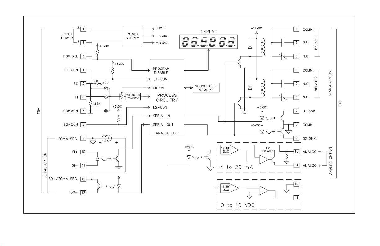
BLOCK DIAGRAM
*Reference Installation and Connections section for power connection.
Note: Analog “-” and Alarm common are separate and isolated from the signal common. The commons should NOT be tied together.
-5-
Page 8

PROGRAMMING AND OPERATING THE IMY
PROGRAMMING THE IMY
Although the unit has been programmed at the factory, the set-ups will
generally have to be changed to suit the application. Basic set-up is complete
after selection of the temperature units, decimal point placement, and
selection of the digital filtering level.
Before actually tryingto program the indicator, itis advised to organize all
the data for the programming steps to avoid any possible confusion and to
read the programming procedure entirely before proceeding.
To set-up the indicator, connect primary power and signal wires as
outlined in the connections section (Appendix “A”). Remove the jumper
wire (if installed) fromTBA#3 (PGM. DIS.). This will allowtheoperator to
enter and modify all of the indicator’s parameters. Press the front panel
button labeled “P”, momentarily. Briefly, the display will show “Pro”
alternately flashing with “0”. This is the indicator’s programming mode.
The programming mode is divided into sections, numbered 0-9, each of
which can be individually accessed. The front panel “UP” and “DOWN”
arrow buttons canbe used to select one of these numbers and the “P” button
can be used to enter the selected programming module. In all of the
programming modules, “UP”and “DOWN” are usedto either select from a
list of choices or enter a value. The “P” button is used to save the new value
and progress to the next step within a module (Note: the new value takes
effect when “P” is pressed). Upon completion of a module, the indicator
returns to the “Pro” <>“0” stage. Pressing the “P” button at this time
causes the unit to display “End” after which the unit returns to the normal
display mode. The following table explains the basic function of each step.
Note: < > This indicates that the display will alternate between the English
prompt and the actual data.
-6-
Page 9

DISPLAY RESULT OF “P” BUTTON
DISPLAY
RESULT OF “P” BUTTON
“Pro” <>“0” - Causes the indicator to return to normal display mode.
Any changes to set-up data are permanently stored in the
2
E
PROM.
“Pro” <>“1” - Entry into this module allows the user to select the
Thermistor type, whether the display will read in degrees
Fahrenheit (F) or Celsius (C), and display decimal point
position.
“Pro” <>“2” - Entry into this module allows the user to select
non-standard display slope and display offset values.
This enables the meter to be “scaled” to a calibrated
temperature probe. (This scaling is NOT required for
most applications.)
“Pro” <>“3” - Module #3 allows the user to program what can be
accessed from the front panel when the PGM. DIS.
(Program Disable, TBA #3) pin is connected to common.
This feature protects critical set-up data from accidental
modification while allowing access to setpoints and other
functions. The front panel lock-out menu (quick
programming) includes setpoint modification,
integrator/totalizer resetting, and peak/valley resetting.
Note: Theterm “Quick Programming”is used to refer to the
ability to change the information that can be accessed from
the frontpanelwhen the “PGM. DIS.”terminalis connected
to “COMM.”.
“Pro” <> “4” - Module #4 programs the digital filtering level and the
function of the remote input “E1-CON” pin (TBA #4),and
if the totalizer option is installed, the remote input
“E2-CON” pin (TBA #8). The functions of the remote E1
and E2 pins are the same and include display hold,
peak/valley modes, totalizer reset, alarm reset, temperature
offset, reading synchronization or print request.
“Pro” <>“5” - This module sets the time base, scale factor and low
temperature disable function for the optional integrator/
totalizer.
“Pro” <>“6” - This module allows programming for the basic
configuration of the alarm option. The programming
includes HI/LO acting, tracking, alarm display, latched
or auto-reset, assignment to either the input or the
integrator/totalizer, and alarm and hysteresis values.
“Pro” <>“7” - Module #7 is the serial communication parameter
programming. Baud rate, unit address, print request
function and condensed prints are all programmable.
“Pro” <>“8” - This module allows digital scaling of the retransmitted
analog output. Display values that correspond to 4mA or
0 VDC and 20 mA or 10 VDC are keyed-in to scale the
output and it may be assigned to either the input or the
integrator / totalizer.
“Pro” <>“9” - This module is the service operation sequence and is not
normally accessed by the user. This step re-calibrates the
basic input and is used to compensate for long-term drift.
Execution of this module should be done by technicians
with the proper equipment in accordance with a
maintenance plan of yearly recalibrations. A code number
entry step isused to protect frominadvertent entries. Also,
there is a number of other access codes which provide test
and set-up changes as an aid in troubleshooting.
-7-
Page 10

MODULE #1 - PROGRAM THERMISTOR TYPE, TEMPERATURE SCALE (F OR C)
AND DECIMAL POINT POSITION
Select the desired Thermistor type by pressing the “UP” or “DOWN”
button.
“tYPE” < > “400” 400 = 400 Series, 2,252 ohm
Select the desired temperature scale by pressing the “UP” or “DOWN”
button.
Select the desired decimal point location by pressing the “UP” or
“DOWN” button.
“700” 700 = Thermolinearä Series
“SCALE” < > “F”
“C”
“ dECPNt” < > “0”
“0.0”
MODULE #2 - PROGRAM TEMPERATURE DISPLAY OFFSET AND SLOPE
If the totalizer option is installed, the offset and slope can be programmed
for various temperature probe differences. See the Offset and Slope Display
Temperature section for more details.
Select the desired temperature displayslope value bypressing the “UP”or
the “DOWN” button.
“SLOPE” < > “0.0001” to “10.0000” (ex. 1.0309)
Select the desiredtemperature display offset value bypressing the “UP” or
the “DOWN” button.
“OFFSEt” < > “-999” to “9999” (ex. -17.5)
-8-
Page 11

MODULE #3 - PROGRAM FUNCTIONS ACCESSIBLE W/ FRONT PANEL LOCKOUT
This programming module programs what is accessible through the front
panel when the PGM. DIS. pin is connected to common (COMM.).
Note: The term “QuickProgramming” is used to refer to the abilityto change the
information that can be accessed from the front panel when the “PGM. DIS.”
terminal is connected to “COMM.”.
DISPLAY ALARM VALUES
If the alarmoption is installed, this selectswhether the alarm values willor
will not be displayed.
“dSP AL” < > “yES” or “NO”
ENTER ALARM VALUES =
If “YES” was selected for display alarm values, this will select if alarm
values may be modified from the front panel. (If “NO” was selected for
display alarm values, then this step will default to “NO” and will not be
displayed for selection.)
“ENt AL” < > “yES” or “NO”
DISPLAY HYSTERESIS VALUES
If the alarm option is installed, this selects whether the hysteresis values
will or will not be displayed.
“dSPHYS” < > “yES” or “NO”
ENTER HYSTERESIS VALUES =
If “YES” was selected for display hysteresis values, this selects whether
hysteresis values may be modified from the front panel. (If “NO” was
selected for display hysteresis value, then this step will default to “NO” and
will not be displayed for selection.)
“ENtHYS” < > “yES” or “NO”
= Note: This sequence may be locked-out due to other programmed sequences.
* Note: This function operates independent of the state of the “PGM. DIS.” pin.
RESET LATCHED ALARMS
If the alarm option is installed and if either alarm is programmed to latch,
this will select if a latched alarm(s) can be reset from the front panel.
“rSt AL” < > “yES” or “NO”
DISPLAY PEAK/VALLEY MEMORY BUFFER
If the integrator/totalizer option is installed, this selects whether peak and
valley buffers will be displayed.
“dSPbUF” < > “yES” or “NO”
RESET PEAK/VALLEY MEMORY BUFFER =
If “YES” was selected for the previous step, this selects whether the peak
and valley buffers may be reset from the front panel. (If “NO” was selected,
then this step defaults to “NO” and will not be displayed for selection.)
“rStbUF” < > “yES” or “NO”
SELECT DISPLAY*
If the integrator/totalizer option is installed, this selects whether the
display can be switched from input display to total display and from total
display to input display.
Note: When “NO” is selected, whatever display (Input or total) is shown, willbe
the only display accessible.
“SELdSP” < > “yES” or “NO”
RESET TOTAL*
If the integrator/totalizer option is installed, this selects whether the total
can be reset from the front panel.
“rSttOt” < > “yES” or “NO”
-9-
Page 12

TEMPERATURE OFFSET VALUE =
If the Integrator/Totalizer/Peak/Valley/Temperature Offset option is
installed, this selects whether the programmed offset value will be displayed.
“dSPOFF” < > “yES” or “NO”
ENTER OFFSET VALUE =
If “YES” was selected for the previous step, this selects whether the offset
value can be entered from the panel. (If “NO” was selected, then this step
defaults to “NO” and will not be displayed for selection.)
“ENtOFF” < > “yES” or “NO”
Depending on functionsselected under Pro 3and Pro 6, alarms,hysteresis,
peak, valley and offset values can be monitored and/or changed with PGM.
DIS. istied to COMM. This provides a “QUICK PROGRAMMING” method
for “day to day” process changes. (See QUICK PROGRAMMING SECTION
for more details.)
= Note: This sequence may be locked-out due to other programmed sequences.
* Note: This function operates independent of the state of the “PGM. DIS.” pin.
-10-
Page 13

MODULE #4 - PROGRAM DIGITAL FILTER AND REMOTE INPUT
PROGRAM DIGITAL FILTERING
If the displayed process signal is difficult to read due to small process
variations or noise, increased levels of filtering will help to stabilize the
display. This programming step may be used in conjunction with display
rounding programming (Pro1&2)to help minimize this effect. Although the
digital filter features a “moving window” to help minimize response time,
higher degrees of filtering levels will have slightly longer response times.
“FILter” < > “0” - no digital filtering
PROGRAM FUNCTION OF E1-CON AND OPTIONAL E2-CON
The function of the remote input “E1-CON” (TBA #4) and, if the totalizer
option is installed, the remote input “E2-CON” (TBA #8) are the same.
Functions are activated, as described in the appropriate function, when
connected to signal common (TBA #7). Whether a function is edge or level
activated, it must be held low for a minimum of 20 msec in order for the
function to occur.The remote input pinscan be used simultaneously andwith
any combination of functions. When pins are tied together and activated,
E1-CON function is generally performed first.
“E1-CON”< > “0” - If the Totalizer/Peak/Valley/Display Offset option is
“1” - normal filtering
“2” - increased filtering
“3” - maximum filtering
installed, a negative going edge offsets the displayed
temperature to zero. (At the timethe E-Pin is activated,
the value of the actual temperature being displayed is
placed in the location of the display offset value. To
bring the unit into the normal temperature display
mode, reset the offset value to zero via the front panel.)
“1” - A negative going edge resets the contents of the
totalizer to zero. Totalization commences regardless
of the state of the remote input.
“2” - A negative going edge resets the contents of the
totalizer to zero and allows totalization as long as the
input is low. If the input goes high, totalization is
stopped and the contents are saved. This acts as a
totalization enable control from Time 1 to Time 2.
“3” - A low level allows totalization as long as the input is
low. If the input goes high, totalization is stopped and
the contents are saved. This acts as a totalization
enable control from Time 1 to Time 2.
“4” - A low levelholdsthe display (display hold). While this
input is low, the indicator continues to process the
input signal and drive the alarms, totalizer, etc., with
the actual signal. The contents of the totalizer are held
at the same time the input display is held.
Note: If display hold is activated, and input value is
requested via serial, the value on the display will be
sent instead of the actual input value at that time.
“5” -A negative going edgeresetsboth peak and valley buffers.
Note: If P/V is called up, a change will not appear on the
display until the next time the P/V is called up.
“6” - A negative going edge resets only the peak buffer and
the indicator enters a peak reading display mode as
long as the input is low. If the input goes high, peak
detection and indication are stopped and the last peak
reading is retained.
“7” - A negativegoing edge resets only the valleybufferand
the indicator enters a valley reading display mode as
long as the input is low. If the input goes high, valley
detection and indication arestopped and the last valley
reading is retained.
“8” - If the alarm option is installed, a negative going edge
resets the latched alarm(s).
-11-
Page 14

PROGRAM FUNCTION OF E1-CON AND OPTIONAL E2-CON
(Cont’d)
“9” - If the alarm option is installed, a low level resets a latched or
unlatched alarm into its inactivestate. This provides manual
override of alarms for system start-up and other unusual
events such as system testing.
“10” - A negative going edge toggles the display between “input”
and “total” (from input to total, or vice versa). No action is
taken on the positive going edge.
“11” - A negative going edge zeros(tares) the input signal and adds
the value that was in the input display to the totalizer value,
every time thisoperation is performed. The time-base, scale
factor and low cut-out in “Module #5” are in affect disabled,
when this function is selected.
“12” - Display hold with offset. Anegative going edge tares (zeros)
the input signal. Prior to the offset operation, the input
signal is saved and held (display hold) as long as the remote
input pin is low. On the positive edge, the input display will
show zero. If there is an increase tothe input signal while the
remote input is low, the display will reflect (show) the
increase at the positive edge.
“13”- Instrument reading synchronization. A lowlevel disables all
meter operations (alarms, total, analog out,etc.). A positive
edge resets the start of the A/D conversion, to allow
synchronization with external processes and controls.
While in this function, the other E-CON pin will be
operational.
“14”- Print request. Transmits data according to the print options
that have been selected in Program Module #7. If the low
time exceeds 800 msec, a second print-out may occur.
“E2-CON”<>Ifthetotalizer option is installed, E2-CON has the
same programmable functions as E1-CON.
-12-
Page 15

MODULE #5 - PROGRAM INTEGRATOR/TOTALIZER
Programming for the integrator/totalizer consists of four programming
steps: totalizer decimal point position, time base, scale factor and low
temperature disable. Note that the decimal point position of the
integrator/totalizer can be set independent ofthe decimal point position of the
input. The totalizer value will roll over and flash when the total exceeds,
999999 or -99999, indicating an overflow condition. Reverse signal input
will cause thetotalizer value to count inthe opposite direction and eventually
no longer be in an overflow condition.
PROGRAM DECIMAL POINT POSITION FOR THE
INTEGRATOR/TOTALIZER
The decimal point position for the totalizer are as follows:
“dECPNt” < > “0”
PROGRAM INTEGRATOR/TOTALIZER TIME BASE
The time base determines the rate at which readings increase. The
integrator/totalizer display is updated
base selected, but longer time bases decrease the magnitudeof each increase.
The three time bases are per second,perminuteandper hour. A constant input
temperature of 100°, for example, would integrate/totalize to 100° in one
second (with a TB of 1 sec.), 100° in oneminute(with a TB of 1 min.), and 100°
in one hour (with a TB of 1 hr.). (Note: Input changes can be made
synchronous to the display by programming E1 or optional E2-CON pin for
function 13, Instrument reading synchronization.) A multiplying scale factor
may be used to span the standard time ranges (or divide if scale factor < 1).
The following equation expresses the integration/totalization process.
D.T.
S.F. =
I.D. TIME I.D.D.P.
S.F. = Programmable Scale Factor
D.T. = Desired Totalizer value for a
fixed time duration
T.B. = Programmable Time Base
T.B.xD.T.D.P.
x
“0.0”
“0.00”
“0.000”
“0.0000”
1
times per second regardless of time
2
2
TB = If Program Select Number Chosen Is:
D.T.D.P. = Desired Totalizer Value Decimal Point
I.D.D.P. = Input Display Value Decimal Point
“tbASE” < > “0” - per second
PROGRAM THE INTEGRATOR/TOTALIZER SCALE FACTOR
As explained in the previous programming step, a multiplying scale factor
can be used to scale the update rate as required. This may be used to span the
standard ranges. A scale factor of “1.000” has no effect on the standard ranges.
“0” for sec. 1
“1” for min. 60
“2” for hr. 3600
I.D. = Input Display Value
TIME = Actual Time period in seconds
01
0.0 10
0.00 100
0.000 1000
0.0000 10000
01
0.0 10
“1” - per minute
“2” - per hour
“SCLFAC” < > “0.001” to “100.000”
Enter in Formula
Enter in Formula
Enter in Formula
PROGRAM THE LOW-END CUTOUT (low temperature level
disable)
In order to prevent false integration/totalization in situations where
integration/totalization is undesirable, a programmable setpoint can be used
to disable integration/totalization whentheinput temperature falls below this
low-end cutout level.
“Lo-cut” < > “-999” to “9999”
-13-
Page 16

MODULE #6 - PROGRAM ALARM/SETPOINT
If the alarm option is installed, this module is used to configure the
operation of the alarms to a variety of combinations. The programmable
options are HI/LO acting, auto/manual reset (latching), tracking, assignment
to input or integrator/totalizer, display alarms, alarm values and hysteresis
(deadband) values.
ALARM TRACKING
With alarm tracking, whenever alarm #2 is changed, alarm #1 will also
change so that the offset between alarm #2 and alarm #1 remains the same.
This is useful for hierarchical setpoints (pre-alarm and alarm) when one
change applies to both alarm values. When programming from the front
panel, tracking only occurs when PGM. DIS. is low (front panel lock-out
mode, alarm #1 will not appear). Tracking will always occur if alarm #2 is
modified via serial communications independent of PGM. DIS.
“trAc” < > “yES” or “NO”
DISPLAY ALARMS
If display alarms are desired, a message will flash on the display every 5-10
secs when an alarm activates. For alarm 1, the message will flash “AL1 ON”
and alarm 2 will flash “AL2ON”. This warns an operator of an alarm condition.
The message will stop when the unit is no longer in an alarm condition.
“dISP” < > “yES” or “NO”
AUTO OR MANUAL RESET FOR ALARM #1
The reset action of alarm #1 may be programmed to reset automatically
(unlatched) or be programmed to require a manual reset (latched), through
either a remote input (E1-CON or optional E2-CON) or through the front
panel. Latched alarms are usually used when an operator is required to take
some action for the alarm condition.
“LAtC-1” < > “yES” or “NO”
ALARM #1 ASSIGNMENT TO INPUT OR
INTEGRATOR/TOTALIZER
Alarm #1 may be programmed to activate on either the input or the
integrator/totalizer value. If the integrator/totalizer option is not installed,
this step defaults to the input.
“ASN-1” < > “INPUt” or “totAL”
PROGRAM VALUE FOR ALARM #1
The range of the alarm value is -999 to 9,999 for the input display and
-99999 to 999999 for the totalizer option display.
“AL-1” < > “-999” to “9999”
PROGRAM HYSTERESIS VALUE FOR ALARM #1
(Cannot be programmed if alarm latch is programmed)
The hysteresis (deadband) value for alarm #1 may be programmed from 1
to 9,999 for the input and 1 to 999999 for the totalizer option. The value is
either added to or subtracted from the alarm value depending on whether the
alarm is high or low acting. (See “alarm” section for operation.)
“HyS-1” < > “1” to “9999”
ALARM #1 HIGH OR LOW ACTING
The action of alarm#1maybe programmed to activate either when thedisplay
value goes above the alarm value (high acting) or goes below it (low acting).
“Act-1” < > “HI” or “LO”
AUTO OR MANUAL RESET FOR ALARM #2
The reset action of alarm #2 may be programmed to reset automatically
(unlatched) or be programmed to require a manual reset (latched), through
either a remote input (E1-CON or optional E2-CON) or through the front
panel. Latched alarms are usually used when an operator is required to take
some action for the alarm condition.
“LAtC-2” < > “yES” or “NO”
-14-
Page 17

ALARM #2 ASSIGNMENT TO INPUT OR INTEGRATOR/
TOTALIZER
Alarm #2 may be programmed to activate on either the input or the
integrator/totalizer value. If the integrator/totalizer option is not installed,
this step defaults to the input.
“ASN-2” < > “INPUt”or “totAL”
PROGRAM VALUE FOR ALARM #2
The range of the alarm value is -999 to 9,999 for the input display and
-99999 to 999999 for the totalizer option display.
“AL-2” < > “-999” to “9999”
PROGRAM HYSTERESIS VALUE FOR ALARM #2
(Cannot be programmed if alarm latch is programmed)
The hysteresis (deadband) value for alarm #2 may be programmed from 1
to 9,999 for the input and 1 to 999999 for the totalizer option. The value is
either added to or subtracted from the alarm value depending on whether the
alarm is high or low acting. (See “alarms” section for operation.)
“HyS-2” < > “1” to “9999”
ALARM #2 HIGH OR LOW ACTING
The action of alarm#2maybe programmed to activate either when thedisplay
value goes above the alarm value (high acting) or goes below it (low acting).
“Act-2” < > “HI” or “LO”
Note: Depending on options selected under Pro 3 and Pro 6, alarms, hysteresis,
peak, and valley values can be monitored and/or changed when PGM. DIS. is
tied to COMM.This provides a “QUICK PROGRAMMING” methodfor “day
to day” process changes. (See QUICK PROGRAMMING SECTION for more
details.)
-15-
Page 18

MODULE #7 - PROGRAM SERIAL COMMUNICATIONS
Several programmable parameters must be programmed before serial
communication can occur.
BAUD RATE
Select one of the baud rates from the list to match the baud rate of the
printer, computer, controller, etc.
“bAud” < > “300” - 300 baud
UNIT ADDRESS NUMBER
To allow multiple units to communicate on the 20 mA loop, different address
numbers must be assigned to each unit. If only one unit is on the loop, an
address of “0” may be given, eliminating the need for the address command.
“
PRINT REQUEST FUNCTION
A selection of print operations can be programmed. A print operation
occurs when a print request is activated via E1-CON (TBA #4) or optional
E2-CON (TBA #8),ora“P” command is sent from a terminal via the serial
communications option. If the option to which a particular print code applies
is not installed, then that parameter will not be printed.
If the totalizer is overflowed, an asterisk (*) will precede the digits that are
printed (ex. *000127 positive overflow, -*00127 negative overflow). If the
temperature exceeds the range of the unit, the print-out will show
“OLOLOL”. If the sensoropens, the print-out will show“ULULUL”.For the
negative direction or shorted, the print-out will show “SHOrt”.
“600” - 600 baud
“1200” - 1200 baud
“2400” - 2400 baud
“AddrES” < > “0” to “99”
“Print” < > “0” - input signal
FULL OR ABBREVIATED TRANSMISSION
When transmitting data, the IMY can be programmed to suppress the
address number, mnemonics and some spaces, if desired, by selecting “NO”.
A selection of “NO” results in faster transmission. This feature may be
helpful when interfacing with a computer. When interfacing to a printer, a
“yES” response is usually desirable.
An example of full and abbreviated transmission is shown below:
2 INP -125.7F < CR><LF> Full transmission
-125.7 < CR><LF> Abbreviated transmission
“1” - input signal, peak, valley and offset
“2” - input signal, alarm 1 and alarm 2
“3” - input signal, alarm 1, alarm 2, hysteresis 1,
hysteresis 2, peak, valley, and offset
“4” - totalizer
“5” - input signal and totalizer
“6” - input signal, totalizer, peak, valley, and offset
“7” - totalizer, alarm 1, and alarm 2
“8” - input signal, totalizer, alarm 1, and alarm 2
“9” - input signal, totalizer, alarm 1, alarm 2,
hysteresis 1, hysteresis 2, peak, valley, and
offset
“FULL” < > “yES” or “NO”
-16-
Page 19

MODULE #8 - PROGRAM RE-TRANSMITTED ANALOG OUTPUT
This programming module allows digital scaling of the 4 to 20 mA or 0 to
10 VDC analog output. The type of analog output is determined by the model
ordered. (See Ordering Information for available models.) The display value
at which 4 mA or 0 VDC and the displayvalue at which 20mA or 10 VDC are
transmitted are keyed-in. The indicator automatically calculates slope and
intercept values to complete the scaling. The analog output then follows the
calculated display value and as such will update every measurement cycle.
The output may also be programmed to proportionally re-transmit the
contents of the totalizer instead of the input. Reverse acting output can be
achieved by programming the “high” display value for the “AN-LO”
programming step and the “low” display value for the “AN-HI” step.
Note: DO NOT ADJUST THE ANALOG OUTPUT POTS ON THE BACK OF
THE UNIT. Fine offset and span adjustment pots are externally accessible to
compensate for small drifts in the output. These pots have been set at the
factory and do not normally require adjustment.
ANALOG OUTPUT SOURCE
Program whether the input or the totalizer will serve as the basis for the
analog output signal. If the integrator/totalizer option is not installed, then
this step defaults to “Input”.
“ASIN” < > “INPUt” or “totAL”
ANALOG OUTPUT LO DISPLAY VALUE
Program the display value at which the analog output transmits 4 mA or 0
VDC.
“AN-Lo” < > “-999” to “9999” for “INPUt”
ANALOG OUTPUT HI DISPLAY VALUE
Program the display value at which the analog output transmits 20 mA or
10 VDC.
“AN-HI” < > “-999” to “9999” for “INPUt”
“-99999” to “999999” for “totAL”
“-99999” to “999999” for “totAL”
-17-
Page 20

MODULE #9 - SERVICE OPERATIONS
The indicator has been fully calibrated at the factory. If the unit appears to
be indicating incorrectly or inaccurately, refer to the troubleshooting section
before attempting this procedure.
When re-calibration is required (generally every 2 years), this procedure
should only be performed by qualified technicians using appropriate
equipment. Resistance source accuracies of 0.01% or better are required.
The procedure consists of applying accurate signal levels to the indicator in
a series of two steps. Allow a 30 minute warm-up period before starting this
procedure.
Note: Once the access code has been entered, there is no exiting the program
module without completing the calibration procedure.
ENTER ACCESS CODE
“Code 48” must be keyed-in prior to the calibration sequence to guard
against inadvertent entries. Access code numbers other than those listed in
this section should not be entered at this step. If any areentered, undefined or
unpredictable operation could result.
If the code number for the previous step was not recognized, the indicator
returns to “Pro 0”, with no action taken.Otherwise, thecalibration procedure
is started.
ENTER ZERO REFERENCE
Apply 0 ohms to input by shorting Terminals 6 and 7 as
shown in the drawing to the right. Allow to stabilize for 20
seconds before pressing “P”.
APPLY PRECISION RESISTANCE
Connect a precision (0.01%) 5.11 KW resistor across
Terminals 6 and 7.
Allow to stabilize for 20 seconds before pressing “P”.
“CodE” < > “0” to “99”
“StEP 1” (Press “P”)
“StEP 2” (Press “P”)
Indicator calibration is complete. It is recommended that calibration be
checked by comparing the displayed temperature with a precision thermometer.
SERIAL HARDWARE (loop-back) DIAGNOSTICS
The internal serial communications hardware in the IMY can be tested to
verify proper operation. The procedure consists of connecting the Serial
Input (SI), Serial Output (SO), and
20 mA Source into a simple loop,
and then entering an access code.
Connect the IMY as shown at
right. Enter “Pro 9”, key-in “Code
39”, and thenpress “P”. If the serial
communication hardware is OK,
“PASS” will be displayed.
Conversely, if there is an internal
problem, “FAIL” will be displayed.
After the diagnostic test iscomplete,
press “P” to return to “Pro 0”.
“CodE” < > “39”
RESTORING ALL PROGRAMMING PARAMETERS BACK TO
FACTORY CONFIGURATION
All of the programming in Modules #1 through #8 can be restored back to
the factory configuration by entering a specific access code (refer to the
“Factory Configuration” section for the data that will be entered). The
procedure consists of entering “Pro 9”, keying-in “Code 66”, then pressing
“P”. The IMY responds by displaying “INItAL” for several seconds, and
then returns to “Pro 0”.
Note: When this procedure is performed, all of the scaling, presets, etc. that
were programmed into the IMY will be overwritten.
“CodE” < > “66”
-18-
Page 21

OPERATING THE IMY
After completing all set-up operations, the unit is ready to install and
operate. After power is applied, a display test consisting of illuminating all
segments for 2 seconds is performed. Afterward, the input or total will
appear, depending upon the display mode prior to the last power-down. To
switch the display to input, press “DOWN” (indicated by “arrows” on the
front panel) and to switch it to total, press “UP”. If the integrator/totalizer
option isnot installed, then display switching to total is inoperative. A minus
sign “-” will precede numbers that are negative.
QUICK PROGRAMMING
To limit access tothe set-up parameters, connect a key-switchor wire from
PGM. DIS. (TBA #3) to COMM. (TBA #7). With this pin connected to
common, only a predetermined amount of data can be viewed or altered, as
programmed by programming module #3. If “NO” was programmedfor allof
the available steps in module #3, then pressing “P” will cause the unit to
display “Loc”. However, if “YES” was programmed in one or more of the
steps, then “P” will invoke entry into a series of commonly modified
parameters while protecting thecrucialset-up information. This is referred to
as the “quick programming” mode. When “quick programming” mode is
entered, the alarms and hysteresis values can be modified inthe same manner
as in the regular programming mode. The new alarm and hysteresis values
will take effect when “P” is pressed.
The other operations in the “quick programming” mode require special
key sequences as shown:
To reset latched alarm, scroll through steps in “quick
programming” mode using the “P” button until “LAtCH1” or
“LAtCH2” appears inthe display. If they do not appear, they are
not latched.
To reset: While “LAtCH1” or “LAtCH2” is being
displayed, press and hold“DOWN”and press “P”.
Pressing “P” alone causes a step to the next item
with no action on the alarm.
To reset peak and valley buffers, scroll through steps in “quick
programming” mode using the “P” button until “PEA” or
“VAL” appears in the display.
To reset: While “PEA” or “VAL” is being
displayed, press and hold“DOWN”and press “P”.
Pressing “P” alone causes a step to the next item
with no action taken on the buffer.
The front panel buttons are not only used to input data during the
programming and “quick programming”mode,but control a number of other
functions (if enabled in Pro “3”) as well. In the normal meter mode, these
functions are available:
To switch to display of input: Press “DOWN” button.
To switch to display of totalizer: Press “UP” button.
To reset totalizer to zero: Press and hold “UP” and press “P”.
To enter programming or “quick programming”: Press “P”.
After each operation, a message will appear briefly to acknowledge the action.
-19-
Page 22

FACTORY CONFIGURATION
The following chartliststhe programming of the unit whenshipped from the
factory. (In Program Module #9, Code 66 will restore the unit to these values.)
“Pro 1”..... “tYPE” - “700”
“SCALE” - “F”
“dECPNt” - “0.0”
“Pro 2”..... “SLOPE” - “1.0000”
“OFFSEt” - “0.0 F”
“Pro 3”..... “dSP AL” - “yES”
“ENt AL” - “yES”
“dSPHYS” - “yES”
“ENtHYS” - “yES”
“rSt AL” - “yES”
“dSPbUF” - “yES”
“rStbUF” - “yES”
“SELdSP” - “yES”
“rSttOt” - “yES”
“dSPOFF” - “yES”
“ENtOFF” - “yES”
“Pro 6”..... “trAc” - “NO”
“dISP” - “NO”
“LAtC-1” - “NO”
“ASN-1” - “INPUt”
“AL-1” - “0.0 F”
“HYS-1” - “0.1 F”
“Act-1” - “HI”
“LAtC-2” - “NO”
“ASN -2” - “INPUt”
“AL-2” - “0.0 F”
“HYS-2” - “0.1 F”
“Act-2” - “HI”
“Pro 7”..... “bAud” - “1200”
“AddrES” - “0”
“Print” - “0”
“FULL” - “yES”
“Pro 8”..... “ASIN” - “INPUt”
“AN-Lo” - “0.0 F”
“AN-HI” - “100.0 F”
“Pro 4”..... “FILter” - “1”
“E1-CON” - “4” (Display Hold)
“E2-CON” - “4” (Display Hold)
“Pro 5”..... “dECPNt” - “0”
“tbASE” - “0”
“SCLFAC” - “1.000”
“Lo-cut” - “0.0 F”
-20-
Page 23

PROGRAMMING EXAMPLE
As an exampleofa programming sequence, the following values,gainedfrom
a temperature-time monitoring application, are programmed into the indicator.
DISPLAY: Display the actual temperature of a liquid solution in °F.
Activate alarm #1 output when temperature falls below 25°F, activate
display alarm. Peak and valley (max/min) readings for each cycle to be
recorded.
TOTALIZER: When total exceeds 30,000 degree-minutes then latch alarm
#2 which stops the heating process and sounds a process complete bell.
Reset alarm #2 by remote input. Disable totalization when temperature
falls below200°F. Reset the total from the front panel. Allow switching of
the display from/to temperature and total.
SERIAL: Provide hardcopy printout of total, input and peak/valley when
operator actuates print request. Baud rate 300.
ANALOG RE-TRANSMISSION: Record temperature profile. 4 mA at
50°F and 20 mA at 200°F.
“Pro 1”..... “tYPE” - Enter 400
“SCALE” - Enter F
“dECPNt” - Enter 0
“Pro 2”..... “SLOPE” - Enter 1.0000
“OFFSEt” - Enter 0
“Pro 3”..... “dSP AL” - Enter yes
“ENt AL” - Enter yes
“dSPHYS” - Enter no
“rSt AL” - Enter no
“dSPbUF” - Enter yes
“rStbUF” - Enter yes
“SELdSP” - Enter yes
“rSttOt” - Enter yes
“dSPOFF” - Enter no
“Pro 4”..... “FILter” - Enter 1 (Normal)
“E1-CON” - Enter 7 (reset alarm #2)
“E2-CON” - Enter 14 (print request)
“Pro 5”..... “tbASE” - Enter 1
“SCLFAC” - Enter 1.000
“Lo-cut” - Enter 200
“Pro 6”..... “trAc” - Enter no
“dISP” - Enter yes
“LAtC-1” - Enter no
“ASN-1” - Enter input
“AL-1” - Enter 25
“HYS-1” - Enter 1
“Act-1” - Enter LO
“LAtC-2” - Enter yes
“ASN -2” - Enter total
“AL-2” - Enter 30000
“HYS-2” - N/A
“Act-2” - Enter HI
“Pro 7”..... “bAud” - Enter 300
“AddrES” - Enter 0
“Print” - Enter 6
“FULL” - Enter yes
“Pro 8”..... “ASIN” - Enter input
“AN-Lo” - Enter 50
“AN-HI” - Enter 200
-21-
Page 24

TEMPERATURE MONITORING EXAMPLE
An IMY is installed as a monitoring device and back-up
controller for a freezer storage facility. Normally, the
freezer temperature is maintained at about -29°C ±2°. The
absolute maximum allowable temperature of the freezer is
0°C. In the event of a system failure, alarm output#1 of the
IMY is programmed to start a secondary cooling system
should the temperature reach 0°C. The additional alarm of
the IMY is used to signal personnel with a warning bell
when the temperature rises above -17°C (indicating a
possible failure of the main cooling system). This alarm is
programmed to latch in order to assure that personnel
inform maintenance of a possible problem. Key switches
are installed to lock out the front panel from unauthorized
personnel and to provide a means of resetting the latched
alarm. The Integrator/totalizer option is specified to store
peak and valley temperatures overnight, weekly, etc.
Programming module #5 (Pro 5) is used to set up the
integrator. The re-transmitted analog output isspecified to
drive a chart recorder with 4-20 mA for a hard copy of
temperature profiles for later evaluation.
-22-
Page 25

INTEGRATOR / TOTALIZER / PEAK / VALLEY / TEMPERATURE OFFSET (Optional)
INTEGRATOR/TOTALIZER
The integrator/totalizer option simply adds input readings together using a
programmable time base and scaling coefficient. The decimal point position
of the integrator/totalizer canbe programmed independent of the scaledinput
signal. The integrator/totalizer may be reset through a remote input, by the
front panel or through the serial communications option. Alarms may be
programmed to trigger from integrator/totalizer values; for example to total
“degree minutes” for batching operations. The programmable time bases are
“per second”, “perminute”and“perhour”,meaningthe integrator/totalizer
will accumulate at a fixed rate of
input level over the selected time period. For example, if the input is a
constant 100° and the “per minute” time base is selected, the
integrator/totalizer will accumulate at the rate of 100° per minute. The
totalizer is updated at this rate every 400 msec. As a result, the input is
accumulated in “batches” of 6.6 counts every 400 msec. Therefore, the
totalizer start and stop sequencing, as wellas alarm values set for triggering at
specific totalizer values, are only accurate to the 400 msec totalizer update
rate. The preceding example requires a scale factor of 1.000 to yield exact
time bases, but any scale factor can be used to span between the ranges. (See
section on integrator/totalizer programming for detailed information.) A
programmable low temperature level disable feature completes the
integrator/totalizer features (this will stop totalization when the input drops
below this programmed value, “low cut”). At loss of power to the indicator,
the contents of the integrator/totalizer is saved. This will allow
integrating/totalizing of interrupted processes. The total can accumulate to
999,999. If the low-end cut-out value is programmed negative (ex. -100,
reference Program Module #5), and the inputdisplay value is between zero and
the low-end cut-out value, the totalizer value will decrement. If the input
display value goesabove zero the total will increment.If the display value goes
below (more negative than), the low-end cut-out value, totalization will stop.
1
times per second and be equal to a fixed
2
2
PEAK/VALLEY
The other features of the integrator/totalizer option are peak and valley
detection. The indicator will record the lowest reading (valley) and the
highest reading (peak), automatically, for later recall. This information is
valuable in monitoring the limits of the process over any length of time since
these values are stored at power-down to span over shifts, days, etc. An
external input can be programmed to reset or engage the unit into a
peak/valley reading indicator. Additionally, the peak and valley can be
viewed and reset from the front panel, if so programmed, and viewed and reset
from the serial communication option.
Note: The peak/valley measurement is not instantaneous, and is based on a
nominal 2 sec. response time.
OFFSET AND SLOPE DISPLAY TEMPERATURE
If a difference exists between the displayed temperature and a reference
temperature point, the display may be offset for this effect. Similarly, a
correcting “slope” may be programmed, with the offset, to allow for two
point temperature correction.
For most applications,theslope and offset values are notchanged. But if it is
required to scale the display tomatch a calibrated probe,the following formula
and example show the calculation of appropriate slope and offset values.
Desired Display = (slope x actual temp. display) + offset
difference of two desired temperature points
slope =
offset = one desired temperature point - (slope x one
Example:
The meter is displaying 52 degrees and 146 degrees (actual temperature)
when the calibrated temperature reference shows that 50 degrees and 150
degrees respectively should be displayed (desired temperature).
First determine the new slope value using the sets of temperature points.
Next, determine the new offset valueby using either one of the temperature
pairs.
offset = 150 - (146 x 1.0638)
offset = 5.3
difference of two actual temperature points
corresponding actual temperature point)
slope =
150-50
146 - 52 94
=
100
= 1.0638
-23-
Page 26

OFFSET AND SLOPE DISPLAY TEMPERATURE (Cont’d)
SET-UP:
This feature allows the operator to manipulate the displayed temperature
reading. The operator may utilize this feature for example, when switching
thermistor probes, to compensate for differences in thermistor probe
accuracy from one manufacturer to another or to offset the input reading to
match a “Reference” temperature.
The displayed temperature can be offset either positive or negative to the
actual measured temperature. Programming a positive number for the offset
value increases the display value. Programming a negative number for the
offset value decreases the display value. For example, if the displayed
temperature is 10° less than the measured temperature, programming a +10
for the offset value will increase the displayed value by 10 throughout the
entire range. If the displayed temperature is 10° higher than the measured
temperature, programming a -10 for the offsetvalue will decrease thedisplay
value by 10 throughout the entire range.
“Pro 2” ..... “SLOPE” - 1.0638
“OFFSEt” - -5.3
INTEGRATOR/TOTALIZER EXAMPLE
The indicator is employed to indicate average daily (8 hour) temperatureof
a “Hot Room” used for storing various ingredients at a large food processing
plant. Ingredients which must be kept at temperatures above 100.0°F are
stored in this room. The desired constant temperature is 110.0°F. However,
frequent opening and closing of the door causes temperature variations. The
following programming steps are performed:
BASIC SET-UP
“Pro 1”.....“tYPE” - 400
“SCALE” - F
“dECPNt” - 0.0
INTEGRATOR/TOTALIZER SET-UP
With an average temperature input which gives a display of 110.0° at the
end of an 8 hour time period (one shift), the following formula applies:
T.B.
D.T.
S.F. =
S.F. = Programmable Scale Factor
D.T. = Desired Totalizer value for a
T.B. = Programmable Time Base
T.B. = If Program Select Number Chosen Is:
TIME = Actual Time period in seconds
D.T.D.P. = Desired Totalizer Value Decimal Point
I.D.D.P. = Input Display Value Decimal Point
R This value is normally 1, but can be used as a course scale factor of 60 or
3600.
x (
I.D. TIME I.D.D.P.
fixed time duration
“0” for sec. 1
“1” for min. 60
“2” for hr. 3600
I.D. = Input Display Value
01
0.0 10
0.00 100
0.000 1000
0.0000 10000
01
0.0 10
R
x
D.T.D.P.
Enter in Formula
Enter in Formula
Enter in Formula
)
-24-
Page 27

S.F . =
110
110 28800 10
3600RR
x (
(8 Hours x 3600)
S.F. = 1x.125
S.F. = .125
R
)
x
10
“Pro 5”.....“dECPNt” - 0.0
R This value is normally 1, but can be used as a course scale factor of 60 or
3600.
RR Since the time period is in Hrs., the selected T.B. is 3600 (Program select
value = 2) which equals per hour (3600 sec.).
The integrator/totalizer will accumulate up to 99999.9. At the endof the shift,
the average temperature over the previous 8 hours can be read directly. The
integrator/totalizer canthen be reset for thenext 8 hour shift.Anytime during the
shift, the average temperature can be calculated by the following formula:
For example, 6 hours and 37 minutes into the shift the integrator/ totalizer
reads “90.9”. To find the average temperature up to this point:
Av =
The average temperature over the last 6 hours and 37 minutes was 109.9°F.
RRR Time is in hours. The number of minutes must be divided by 60 and then
added to the hours.
“tbASE ” - 2
“SCLFAC” - .125
“Lo-cut ” - 0.0
Av =
I.V. = Integrator/Totalizer Value
S.F. = Programmable Scale Factor
T.T. = Total Time (From the beginning of the shift)
90.9
.125 x 6.6166 .827
I.V.
S.F. x T.T.RRR
90.9
=
Av = 109.9
-25-
Page 28
ALARMS (Optional)
The alarm option consists of an additional printed circuit board with nine
terminals. Six of these terminals are the two Form-Crelays andthe other three
are the two open collector transistors, which act in parallel with the relays.
The two alarms are completely independent with programmable values,
hysteresis (deadband), high or low acting, auto or manual reset, triggering
from input or total, and tracking one another, if desired. If the alarms are
programmed to latch (manual reset), then they will have to be reset either by
the front panel or remote input. The alarms can be made to trigger from the
integrator/totalizer instead of the input, to activate external alarms, control
valves, etc. Additionally,thealarms may be programmed toactivate an alarm
display to alert operators of the condition.
Alarm #1 can be made to track Alarm #2 byenabling alarmtracking.This is
useful in alarmset-ups where a pre-warning control activates before a second
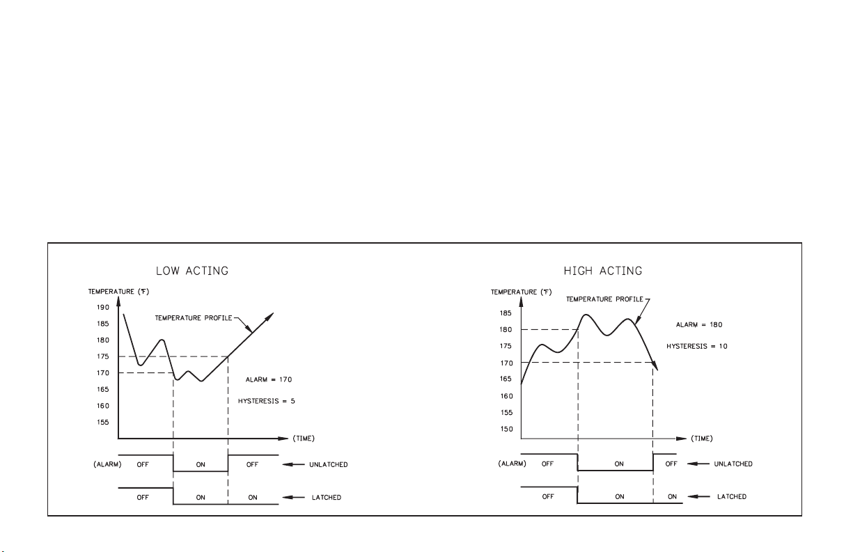
ALARM TIMING DIAGRAMS
alarm shuts off the process. When tracking is programmed, changing the
shut-off trip value (Alarm #2) automatically changes Alarm #1 so that the
offset between Alarm #2 and Alarm #1 remains the same. Alarm and
hysteresis values can be modified through the optional serial
communications to provide automatic control. The following diagrams
depict how the alarms work with both “HI” and “LO” acting set-ups.
Programming of the alarms can be accomplished in the normal
programming mode “Pro6”or the unit can beprogrammed so that the values
can only be changed in the “quick programming” mode.
If the display should indicate an “OLOLOL”, “ULULUL”,or“SHort” the
alarms will de-energize, whether they are latched or unlatched.
Note: Alarm Comm. (TBB #8) must be kept isolated from analog “-”.
-26-
Page 29
20 mA CURRENT LOOP SERIAL COMMUNICATIONS (Optional)
GENERAL DESCRIPTION
The serial communication option is a half-duplex, two-way, 20 mA loop
that can connect to avariety of printers,computers, terminals and controllers
to suit many data-polling or automatic operation applications. The indicator
responds to a hostofcommands, including change alarm value, resettotalizer
and transmit input value. Two loops are required for all hook-ups; a transmit
(out-going data) loop and a receive (in-coming data)loop. Sincethe indicator
monitors the receive loop for a busy signal (current interrupted) while
transmitting, the receive loop must be connected even if the indicator is
transmitting only, such as to a printer. A built-in 20 mA sourcecan be used in
the transmit loop (only) by connecting the current return wire to -20 mA
SRC., instead of SO+. To bypass the built-in current source, make transmit
loop connections to SO+ and SO-.Additionally, multiple units and other Red
Lion Controls instruments can be serially addressed, up to a maximum of 99
units. (The actual number in a single loop is limited by the serial hardware
specifications.) To eliminate problems with ground loops, the serial circuitry
is isolated from both signal common and output common. Optional 20 mA to
RS232C and 20 mA to RS422 converter modules expand the unit’s flexibility.
Note: When operating the unit with a printer, the receive loop of the indicator
must have current flowing into it before transmission can take place.
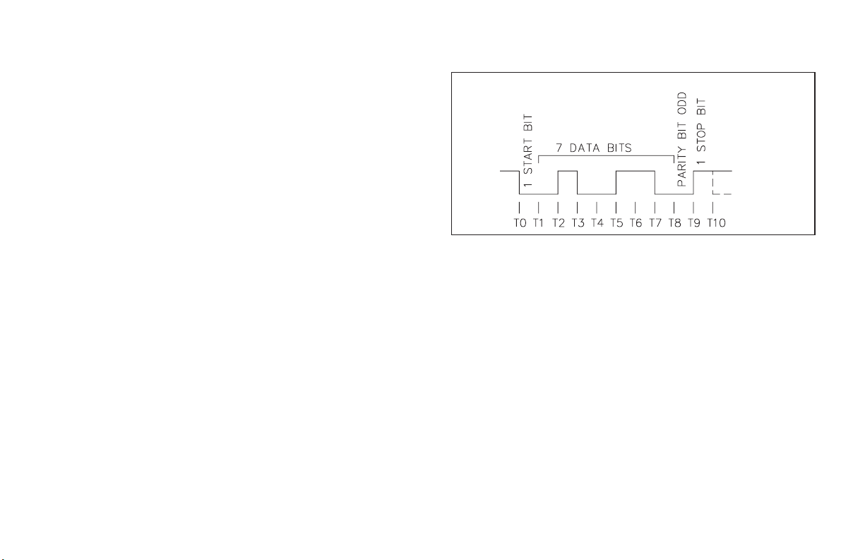
COMMUNICATION FORMAT
Data is sent by switching current on and off in the loop and is received by
monitoring the switching action and interpreting the codes that are
transmitted. In order for data to be correctly interpreted, there must be
identical formats and baud rates among the communicating equipment. The
only format available with thisindicator is 1start bit, 7 data bits, 1 odd parity
bit and 1 stop bit. The baud rates are programmable and the choices are: 300,
600, 1200 and 2400.
DATA FORMAT-10 BIT FRAME [300, 600, 1200, 2400 Baud]
Before serial communication can take place, the indicator must be
programmed to thesame baud rate as theconnected equipment. In addition, the
loop address number, print options and full or abbreviated transmission must
be programmed.If only oneindicator is tobe used, thena loop addressnumber
of “0” mayby used, to eliminate therequirement for the address specifierwhen
sending a command. If more than one indicator is on the loop, assignment of
unique addresses, other than zero, for each indicator is recommended. Valid
addresses of 0 to 99 may be assigned, but the built-in current source, if used, is
capable of drivingup to 7 units. Additionaldrivecapability may be afforded by
an external current source with a higher compliance voltage. Refer to
programming section “Pro 7” to program the serial option.
-27-
Page 30

SENDING COMMANDS TO THE IMY
When sending commands to the unit a command string must be
constructed. The command string may consist of command codes, value
identifiers, and numerical data. Below is a table outlining the codes the
indicator will recognize.
COMMAND FUNCTIONS
T transmits the requested information specified by the
identifier (A-I, K, and L)
V change a value specified by the identifier (C-F, K, and L)
N address a particular indicator in a multiple unit loop (0-99)
R reset a value specified by the identifier (B-D, G, H, I, and J)
P print per programmable print options (A-I)
VALUE IDENTIFIERS SERIAL MNEMONICS
A temperature INP
B integrator/totalizer TOT
C alarm #1 AL1
D alarm #2 AL2
E hysteresis #1 HS1
F hysteresis #2 HS2
G peak reading PEK
H valley reading VAL
I zero offset OFS
J offset input
K analog low ANL
L analog high ANH
Note: RJ - offset the input (re-zeros). When the input is offset (via front panel or
“RJ”) the amount is stored in the offset reading (I). Ex. When an offset is
performed, the display reads “5.0”, the offset value will be “-00005.0” (and
the display will show 0.0).
A command string is constructed by using the above commands and
identifiers along with any data values that are required. The indicator will
accept “+” or “-” in front of the data value. Numbers without “+” are
understood to be positive. Leading zeros can be eliminated and both lower
and upper case characters are accepted. The address command is used to
allow a command to be directed to a specific unit on the loop. If the indicator
is assigned an address of “0”, transmission of the address command is not
required. This is done where only one indicator is in the loop.
The command string is constructed in a specific logical sequence. The
indicator will reject command strings that do not conform. Only one
operation can be performed per command string. Below is a description of
how to construct a command string.
1. If the indicator hasanaddress other than zero, the first two charactersofthe
string must consist of the address command (N) followed by the unit
address number (0-99). If the indicator has an address of 0, the address
command is optional.
2. The next two characters in the string are the actual command the indicator
must perform and the identifier on which it operates. Command P-print,
Value I-zero offset and J-offset input, have implied operators and need no
additional characters.
3. If the change value command is being used (V), the next characters in the
string after the value identifier, are the numerical data. When sending
numerical data, such aschangean alarm value, the correct numberofdigits
to the right, must be included. As an example, to change an alarm value
from 150.2 to 50.0. Sending 50 would cause the indicator to see 5.0 and
change the alarm value accordingly.
4. Allcommands must be terminated by an asterisk(*). The indicator will not
respond to any other code. Carriage return and line feed are not valid
terminators and should be suppressed with the character “;”, if using a
BASIC print statement (ex. Print “N9TA*”;).
COMMAND STRING EXAMPLES
Indicator with address 3, transmit temperature reading.
N3TA*
Indicator with address 0, change alarm #1 to 150.
VC150*
Indicator with address 1, reset totalizer.
N1RB*
Indicator with address 99, print the print options.
N99P*
Indicator with address 0, zero the offset value.
RI*
-28-
Page 31
If illegal commandsor characters are sent to theIM, an asterisk (*) mustbe
sent to clear the input buffer. The IM will not respond to an illegal or
incomplete transmission. The diagrams show the difference in the timing
considerations for either Abbreviated or Full Character Transmission, or if a
Reset Command is issued.
Timing Diagrams
(Full Transmission Selected)
(Abbreviated Transmission Selected)
Timing Diagrams
Note: If FullTransmission is selected and thefront panel is being accessedat
the time of transmission, the IM may take as long as 2 seconds to respond.
Reset Command
Independent of Type
of Transmission Selected
-29-
Page 32

RECEIVING DATA FROM THE IMY
Data istransmitted from the indicator whenever a “T” or “P” command is
received via serial communications or a remote input, E1-CON or optional
E2-CON pin is programmed for print request, is activated. If the abbreviated
transmission was programmed, just data will be transmitted with no built-in
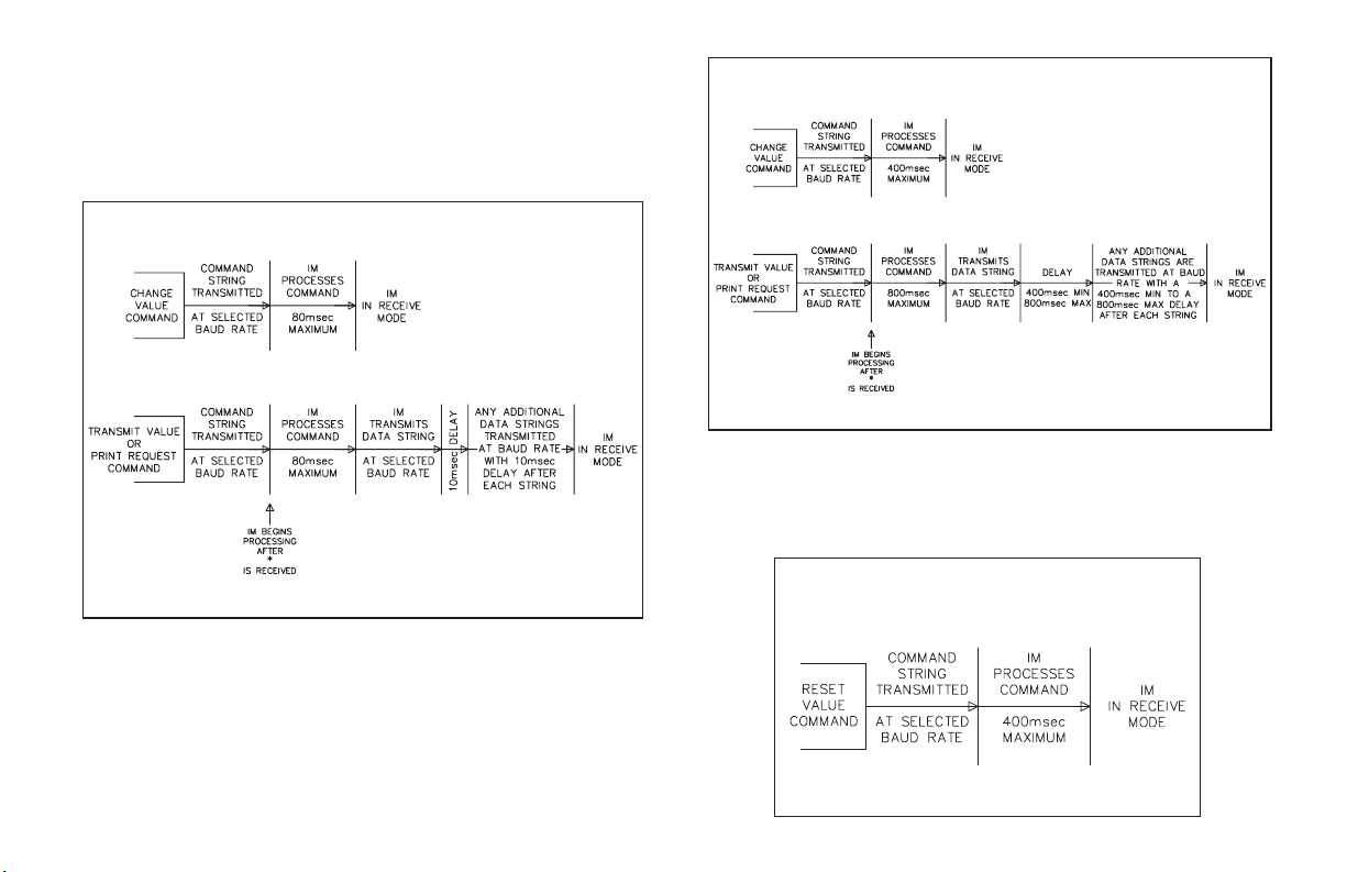
delay. (If full transmission is programmed, then there is a 400 msec min to
800 msec max delay built-in to the string.)
A data string transmission is shown below.
The first two characters transmitted are the unit address number, unless it is
zero, in which case it is left blank. Then two blank spaces are sent. The next
three characters are the abbreviation for the value(mnemonics), which is then
followed by a blank. The actual data is transmitted next. The field is right
justified with leading zeros. Negative numbers are indicated by a minus sign
fixed next to the identifier. A carriage return and a line feed are transmitted
next. For various reasons, “extra” characters are added onto the end of the
above character string. (These characterscould be and are used for control or
signaling purposes.) These characters are:
< CR> sent after single line transmissions from IM unit.
< SP>< CR>< LF> sent after “last line of a block” transmission from IM.
For a “T” command or after each “line of a block” transmission, no
additional characters are sent. If the abbreviated transmission is selected, the
address, mnemonics, and any blank spaces (first eight characters) are not
transmitted (the data strings are left justified in this case).
If the transmitted data is overrunning the peripheral’s buffer, the receive
channel to the indicator may be used for handshaking purposes. As a
consequence of this, even if theindicator is to transmit only (ex. to a printer),
current must be flowing in the receive channel to allow transmission.
Examples of transmissions are as follows:
2 INP -125.7F < CR> < LF > full transmission
-125.7 < CR> < LF > abbreviated transmission
CURRENT LOOP INSTALLATION
WIRING CONNECTIONS
When wiring the 20 mA current loop, remove the bottom terminal block
(TBA), located on the rear of the unit. Refer to the numbers listed with the
terminal descriptions below or those located on the label. It is recommended
that shielded (screened) cable be used for serial communications. This unit
meets the EMC specifications using Alpha #2404 cable or equivalent. There
are higher grades of shielded cable, such as four conductor twisted pair, that
offer an even higher degree of noise immunity. Install each wire in its proper
location on the terminal block. When all connections are made, replace the
terminal block into its proper location.
SERIAL TERMINAL DESCRIPTIONS
8. PRINT REQ. - The PrintRequestterminalis pulled low to activate the unit
to transmit data according to the print function selected in ProgramModule
#7 (Reference Programming Module #7 for more details). In order for a
print request function to occur, E1-CON (TBA #4) or E2-CON (TBA #8)
must be programmed for print request. Note: In order to guarantee a
print-out, the programmed E-CON pin must be held low for at least 20
msec. If this time exceeds 800 msec, a second print-out may occur.
9. -20 mA SRC. - 20 mA current source return path for the transmit loop.
Current flows into this pin.
10. SI+ (Serial In+) -
11. SI- (Serial In-) -
The unit receives commands on the SI terminals. They are connected in
series with the transmit or output terminals of the device to be connected.
12. SO+/+20 mA SRC.(SerialOut+) - 20 mA current sourceforthe transmit
loop (internally connected).
13. SO- (Serial Out-) -
The unit transmits the requested data on the SO terminals. They are
connected in series to the receive input of the device to be connected.
Note: The Serial Input terminals must be held in the mark condition (current
flowing) in order for the unit to respond to a Print Request terminal activation.
-30-
Page 33

SERIAL COMMUNICATIONS EXAMPLES
CONNECTING TO AN RLC PRINTER
The drawing shows the indicator with the 20 mA Serial Communication
Option set-up with an RLC Model DMPC printer. An external current source
is required to implement the printer’s busy signal to the indicator’s receive
loop, which prevents overruns. The “Print switch” is a momentary contact,
push button type connected between the E2-CON (TBA #8) and the signal
common (TBA #7). The print function and E2-CON must be pro- grammed
and the baud rate must match those of the printer. If a printer is used which
does not have a ‘busy’ line, current must still be flowing
receive loop before transmission can occur.
into the indicator’s
-31-
Page 34

PROCESS CONTROLLING SYSTEM
Six Model IMYswith Serial Communication Option
are used to monitor and control the temperature of 6
ovens at a largebakery. The IMYs are located at each of
the ovens in the production area of the building. The
communications lines are run to an industrial computer
located in the production offices.
The drawing below shows the Current Loop set-up.
Each IMY is given an address and programmed
accordingly (Program Module#7). A baud rate of 1200
is selected.
An application program is written, which sends and
retrieves data from the IMYs.
Note: On all IM indicators, the SO+ and the +20 mA SRC
are connected internally. Therefore it is not necessary
to have this terminal tied to any other terminal on the
unit if that unit is serving as the loop supply source.
-32-
Page 35

RE-TRANSMITTED ANALOG OUTPUT (Optional)
The re-transmitted analog output option transmits a digitally
programmable 4 to 20 mA or 0 to 10 VDC signal to drive chart recorders,
remote indicators and controllers. The option is contained on the upper PCB
and has two outputs, “ANALOG-” (TBB #10) and “ANALOG+” (TBB #11)
and is self-powered (active) with a compliance of 10 VDC. The analog “-”
output is isolated from the inputcommon, eliminating problems from ground
loops. Programming of the option is performed in “Pro 8” of the normal
programming mode.Display values are simply keyed in to providea4mAor
0 VDC output, “AN-Lo”, and a 20 mA or 10 VDC output, “AN-HI”. The
analog output then follows the assigned value and as such will update every
measurement cycle. Nonstandard current or voltage ranges can be supported
ANALOG OUTPUT DIAGRAMS
by calculating the slope and intercept of the display/output and calculating
the required display values at 4 mAor 0 VDC and20 mA or 10VDC. Reverse
action can be achieved by programming a “high” display value for “AN-Lo”
and a “low” display value for “AN-HI”.
If the display should indicate an “OLOLOL”, “ULULUL”,or“SHort” the
analog output will go to 20 mA or 10 VDCfor an“OLOLOL”or “SHort”, and
4mAor0VDCfora“ULULUL”.
Note: Analog “-” must be kept isolated from Alarm Comm. (TBB #8).
-33-
Page 36

ANALOG OUTPUT CALIBRATION
Although the analog output has been calibrated at the factory, zero and
span adjustments are provided to compensate for small offsets and drifts. If
excessive drift is noticed, the following calibration procedure may be
performed.
Scale the analog output by entering an arbitrarily larger display value for
“AN-HI” then for “AN-LO”, in “PRO 8”.
Note: Set the analog output source assignment for input.
4 to 20 mA Calibration
Exit the programming mode and apply a (temperature)/(resistance) to the
input of the indicator so that the display reading is below that of the value
entered for “AN-LO”. Adjust the zero potentiometer (right side) so that
exactly 4.00 mA flows, as verified by an accurate ammeter. Next, apply a
(temperature)/ (resistance) to the indicator so that the display reading is
above that of the value entered for “AN-HI”. (See Appendix “B” for max.
input voltage.) Adjust the span potentiometer (left side) so that 20.00 mA is
flowing. Repeat the zero and span adjustments until both are accurate. Analog
output calibration is complete.
0 to 10 VDC Calibration
Exit the programming mode and apply a (temperature)/(resistance) to the
input of the indicator so that the display reading is below that of the value
entered for “AN-LO”. Adjust thezero potentiometer (right side) so that exactly
0.00 VDC flows, as verified by an accurate voltmeter. Next, apply a
(temperature)/ (resistance) to the input of the indicator so that the display
reading is above that of the value entered for “AN-HI”.(See Appendix “B” for
max. input voltage.) Adjust the span potentiometer (left side) so that 10.00
VDC is flowing. Repeat the zero and span adjustments until both are accurate.
Analog output calibration is complete.
-34-
Page 37

APPENDIX “A” - INSTALLATION & CONNECTIONS
INSTALLATION ENVIRONMENT
The unit should be installed in a location that does not exceed the maximum
operating temperature and provides good air circulation.Placing the unit near
devices that generate excessive heat should be avoided.
The bezel should be cleaned only with a soft cloth and neutral soap product.
Do NOT use solvents. Continuous exposure to direct sunlight may accelerate
the aging process of the bezel.
PANEL INSTALLATION
SELECT AC POWER (115/230 VAC)
The AC power to theunitmustbe selected for either 115 VAC or 230VAC.
The selector switch is located through an access slot on the side of the case
(See figure above or label on case). The unit is shipped from the factory with
the switch in the 230 VAC position.
Do not use tools of any kind (screwdrivers, pens, pencils, etc.) to operate
the keypad of the unit.
Before installingthe IM into the panel, the user should first becomefamiliar
with the unit. It may also be desirable to program the unit for the application.
When programming is complete, all parameters will be saved in non-volatile
memory. The Program Disable (PGM.DIS.) terminal should be connected to
COMM. to prevent accidental or unauthorized programming changes.
The unit meets NEMA 4/IP65 requirements for indoor use, when properly
installed. The units are intended to be mounted into an enclosed panel with a
gasket to provide a water-tight seal. Two mounting clips and screws are
provided for easy installation.Consideration should be given to the thickness
of the panel. A panel which is too thin may distort and not provide a
water-tight seal. Recommended minimum panel thickness is 1/8".)
After the panel cut-out has been completed and deburred, carefully slide
the gasket over the rear of the unit to the back of the bezel. Insert the unit into
the panel. As depicted in the drawing,
install the screws into the narrow end of
the mounting clips. Thread the screws
into the clips until the pointed end just
protrudes through the other side. Install
each of the mounting clips by inserting
the wide lip of the clips into the wide end
of the hole, located on either side of the
case. Then snap the clip onto the case.
Tighten the screws evenly to apply
uniform compression, thus providing a
water-tight seal.
Caution: Only minimum pressure is required to seal panel. Do NOT
overtighten screws.
Caution: Make sure the AC selector switch is set to the
appropriate position before applying power to the unit.
Damage to the unit may occur if the AC selector switch is set
incorrectly.
-35-
Page 38

EMC INSTALLATION GUIDELINES
Although this unit is designed with a high degree of immunity to
ElectroMagnetic Interference (EMI), proper installation and wiring methods
must be followed to ensure compatibility in each application. The type of
electrical noise, source or coupling method into the unit may be different for
various installations. In extremely high EMI environments, additional
measures may be needed. The unit becomes more immune to EMI with fewer
I/O connections. Cable length, routing and shield termination are very
important and canmean the difference between a successful or a troublesome
installation. Listed below are some EMC guidelines for successful
installation in an industrial environment.
1. The unit should be mounted in a metal enclosure, which is properly
connected to protective earth.
a. If the bezel is exposed to high Electro-Static Discharge (ESD) levels,
above 4Kv, it should be connected to protective earth. This can be done
by making sure the metal bezel makesproper contact to the panel cut-out
or connecting the bezel screw with a spade terminal and wire to
protective earth.
2. Use shielded (screened)cables for all Signal and Control inputs.Theshield
(screen) pigtail connection should be made as short as possible. The
connection point for the shield depends somewhat upon the application.
Listed below are the recommended methods of connecting the shield, in
order of their effectiveness.
a. Connect the shield only at the panel where the unit is mounted to earth
ground (protective earth).
b. Connect the shield to earth ground at both ends of the cable, usually
when the noise source frequency is above 1 MHz.
c. Connect the shield to common of the unit and leave the other end of the
shield unconnected and insulated from earth ground.
3. Never runSignal or Control cables in thesame conduit or raceway withAC
power lines, conductors feeding motors, solenoids, SCR controls, and
heaters, etc. The cables should be run in metal conduit that is properly
grounded. This is especially useful in applications where cable runs are
long and portable two-way radios are used in close proximity or if the
installation is near a commercial radio transmitter.
4. Signal or Control cables within an enclosure should be routed as far away as
possible from contactors, control relays, transformers, and other noisy
components.
5. In extremely high EMI environments, the use of external EMI suppression
devices, such as ferrite suppression cores, is effective. Install them on
Signal and Control cables as close to the unit as possible. Loop the cable
through the core several times or use multiple cores on each cable for
additional protection. Install line filtersonthepower input cable to the unit
to suppress power lineinterference.Install them near the power entry point
of the enclosure. The following EMI suppression devices (or equivalent)
are recommended:
Ferrite Suppression Cores for signal and control cables:
Fair-Rite # 0443167251 (RLC #FCOR0000)
TDK # ZCAT3035-1330A
Steward #28B2029-0A0
Line Filters for input power cables:
Schaffner # FN610-1/07 (RLC #LFIL0000)
Schaffner # FN670-1.8/07
Corcom #1VR3
Note: Reference manufacturer’s instructions when installing a line filter.
6. Long cable runs are more susceptible to EMI pickup than short cable runs.
Therefore, keep cable runs as short as possible.
7. Switching of inductive loads produces high EMI. Use of snubbers across
inductive loads suppresses EMI.
Snubbers:
RLC #SNUB0000
-36-
Page 39

WIRING CONNECTIONS
After the unit has been mechanically mounted, it is ready to be wired. All
conductors should meet voltage and current ratings for each terminal. Also
cabling should conform to approriate standards of good installation, local
codes, and regulations. It is recommended that power supplied to the unit be
protected by a fuse or circuit breaker. All wiring connections are made on
removable plug-in terminal blocks. There is a separate terminal block for the
bottom board (TBA) and optional top board (TBB). When wiring the unit,
remove the terminal block and use the numbers on the label to identify the
position number with theproperfunction. Strip the wire, leaving approx. 1/4"
bare wire exposed (stranded wires should be tinned with solder). Insert the
wire into the terminal and tighten down the screw until the wire is clamped
tightly. Each terminal can accept up to one 14-gauge, two 18-gauge or four
20-gauge wire(s). After the terminal block is wired, install it into proper
location on the PC board. Wire each terminal block in this manner.
POWER WIRING
Primary AC power is connected to terminal1 and 2 (marked VAC 50/60 Hz,
located on the left hand side of the bottom terminal block). To reduce the
chance of noise spikes entering the AC line and affecting the indicator, the
AC power should be relatively “clean” and within the specified ±10%
variation limit. Drawingpower from heavily loaded circuits orcircuits which
also power loads that cycle on and off, (contactors, relays, motors,
machinery, etc.) should be avoided.
SIGNAL WIRING (THERMISTOR)
Meter signal input common is not isolated from PGM. DIS.,
E1-CON, E2-CON; maximum allowable 50 V can be present in
the circuit that is being measured.
Thermistors provide a higher degree of accuracy, stability, and resolution
over other temperature sensing elements, such as platinum RTDs or
thermocouples.
The IMY supports two popular types of thermistors; the 400 Series (YSI
44000) 2,252W thermistor, and the 700 Series “Thermolinearä” thermistor.
Selection of the two types is done in Programming Module #1.
The 400 Series thermistor isa 2-wire sensor.One lead connectsto TBA #6
(T1) and the other lead connects to TBA #7 (comm).
The 700 Series Thermolinearä thermistor is a 3-wire sensor. One lead
connects to TBA #6 (T1) and the common lead connects to TBA #7 (comm).
The third wire is an additional thermistor lead and connects to TBA #5 (T2).
Always refer to the sensor manufacturer’s instructions for probe wiring
connections, if available.
A.C. Powered Basic Connection
USER INPUT WIRING
User inputs (PGM.DIS., E1-CON, and optional E2-CON) are digital inputs
that are active when connected toTBA #5 Common. Any form of mechanical
switch, sinking collector logic with less than 0.7 V saturation may be used.
The use of shielded cable is recommended. Follow the EMC Installation
Guidelines for shield connection.
OUTPUT WIRING
Relay Connections
To prolong contact life and suppresselectrical noise interference due to the
switching of inductive loads, it is good installation practice to install a
snubber across the contactor. Follow the manufacturer’s instructions for
installation.
Note: Snubber leakage current can cause some electro-mechanical
devices to be held ON.
-37-
Page 40

APPENDIX “B” - SPECIFICATIONS AND DIMENSIONS
1. DISPLAY: 4-digit with F/C indication, 0.56" (14.2 mm) high LED, minus
sign displayed for negative temperatures. 6-digits for integrator/ totalizer.
“Flashing” display for totalizer overflow. “ULULUL” displayed for input
overload and “OLOLOL” displayed for underload (negative overload).
2. POWER REQUIREMENTS: Switch selectable 115/230 VAC, ±10%,
50/60 Hz, 14 VA.
Isolation: 2300 Vrms for 1 min. To all inputs and outputs.
Working Voltage: 300 V max., CAT II
3. CONTROLS: Three front panel push buttons for modifying alarm values
and indicator set-up. Two external inputs for disabling the front panel and
controlling programmable functions.
4. SIGNAL INPUT: 2-Wire, 400 Series 2,252 ohm Thermistor; or 3-wire,
700 Series ThermolinearÔ thermistor.
Max. Input Signal Voltage: ±15 VDC.
Input Common potential with respect to earth Common: 50 V max., CAT I
5. OPEN THERMISTOR DETECTION:
Display - “ULULUL”
Setpoint Outputs - Disabled (Deactivated)
Serial Output - “ULULUL” in data field
Integration/Totalization - Disabled
Analog Output -4mA
DIMENSIONS In inches (mm)
Note: Recommended minimum clearance (behindthepanel) for mounting clip installation is 2.1" (53.3)H x 5.5" (140) W.
6. RANGE: 400 Series -40.0° to 125.0°C (-40.0° to 257°F)
700 Series -30.0° to 100.0°C (-22.0° to 212°F).
7. RESOLUTION: 0.1 or 1 degree.
8. ACCURACY: ±0.2°C (0.36°F) ±
9. READING RATE: 2.5 readings/second
1
LSD, @ 23°C and 10 min. warm-up.
2
10. RESPONSE TIME: 2 seconds to settle for step input (increases with
programmable digital filtering)
11. NORMAL MODE REJECTION: 40 dB at 50/60 Hz (may be improved
by programmable digital filtering)
12. COMMON MODE REJECTION: 120 dB, DC to 50/60 Hz
13. INTEGRATOR/TOTALIZER: Front panel button for input/total
display select. External integrator/totalizer reset/enable. Programmable
time-base, scale factor (0.001-999.999) and low-temp cut-out. Maximum
response time 0.2 sec.
14. E1-CON & E2-CON: External remote inputs which allow activation of
various functions. (Reset total, peak indicator mode, trigger mode, etc.)
V
= 0.8 V
IL
MAX;VIH
= 2.0 V
; Response Time = 0.2 sec. Maximum.
MIN
PANEL CUT-OUT
-38-
Page 41

15. ENVIRONMENTAL CONDITIONS:
Operating Temperature Range: 0 to 50°C
Storage Temperature Range: -40 to 80°C
Operating and Storage Humidity: 85% max. relative humidity
(non-condensing) from 0°C to 50°C.
Altitude: Up to 2000 meters
16. SERIAL COMMUNICATIONS (Optional):
Isolation To Signal Input Common: 500 Vrms for 1 min.
Working Voltage: 50 V max., CAT I
Not isolated from all other commons.
Type: Bi-directional 20 mA current loop, 20 mA source provided on
transmit loop. (Powers up to 7 units in a loop with internal current
source).
Baud Rate: programmable 300 to 2400
Maximum address: 99(Actual number in a single loopis limited by serial
hardware specifications.)
Data Format: 10 bit frame, Odd parity (one start bit, 7 data bits, one odd
parity bit, and one stop bit.)
Serial Hardware Specifications:
SO - Output Transistor Rating: V
Note: This will allow up to 28 units maximum in each loop.
SI - Input Diode Rating: V
Note: The compliance voltage rating of the source must be greater
F
max
= 1.25 V
= 30 VDC, V
; 1.5 V
TYP
MAX
SAT
=1V
at 20 mA.
max
than the sum of the voltage drops around the loop. (Typically a 30
VDC powered source would be capable of operating between 18
and 22 units in a loop.)
17. ALARMS (Optional):
Solid State: Two, isolated, sinking open collector NPN transistors acting in
parallel with relays. Imax: 100mA. V
Isolation To Signal Input Common: 500 Vrms for 1 min.
= 1.0 V @ 100 mA. Vmax: 30VDC.
SAT
Working Voltage: 50 V max., CAT I
Not isolated from all other commons.
Relays:
Isolation To Signal Input Common: 2300 Vrms for 1 min.
Working Voltage: 300 V max., CAT II
Type: Form C (2)
Max. Rating: 5 Amps @ 120/240 VAC or 28 VDC (resistive load), 1/8
hp @ 120 VAC (inductive load).
Relay Life Expectancy: 100,000 cycles at max. rating. (As load level
decreases, life expectancy increases.)
18. ANALOG OUTPUT (Optional): Digital scaling and offsetting
Isolation To Signal Input Common: 500 Vrms for 1 min.
Working Voltage: 50 V max., CAT I
Not isolated from all other commons.
4to20mA:
Accuracy: 0.1% of full scale
Resolution: 12 bits
Compliance Voltage: 10 VDC (500 W max. loop resistance)
0 to 10 VDC:
Accuracy: ±(0.1% of reading + 35 mV)
Resolution: 12 bits
Min. Load Resistance: 10 KW (1 mA max.)
19. PEAK/VALLEY/SLOPE/OFFSET (Optional):
Peak and Valley recording. Programmable temperature offset and slope.
-39-
Page 42

20. CERTIFICATIONS AND COMPLIANCES:
SAFETY
IEC 1010-1, EN 61010-1:Safety requirements for electrical equipment for
measurement, control and laboratory use, Part 1.
IP65 Enclosure rating (Face only), IEC 529
Type 4 Enclosure rating (Face only), UL50
ELECTROMAGNETIC COMPATIBILITY
Immunity to EN 50082-2
Electrostatic discharge EN 61000-4-2 Level 2; 4 Kv contact
Electromagnetic RF fields EN 61000-4-3 Level 3; 10 V/m
Fast transients (burst) EN 61000-4-4 Level 4; 2 Kv I/O
RF conducted interference EN 61000-4-6 Level 3; 10 V/rms
Emissions to EN 50081-2
RF interference EN 55011 Enclosure class A
Notes:
Level 3; 8 Kv air
80 MHz - 1 GHz
Level 3; 2 Kv power
150 KHz - 80 MHz
Power mains class A
2
1. Metal bezel of unit connected with ground lead from rear bezel screw to metal
mounting panel.
2. Self-recoverable loss of performance during EMI disturbance at 10 V/m:
Process input and/or analog output signal may vary during EMI disturbance.
For operation without loss of performance:
Unit is mounted in a metal enclosure (Buckeye SM7013-0 or equivalent)
I/O and power cables are routed in metal conduit connected to earth ground.
Refer to the EMC Installation Guidelines for additional information.
21. CONSTRUCTION: Die-castmetal front bezel that meetsNEMA 4/IP65
requirements for wash-down and/or dusty environments when properly
installed. Pollution Degree 2. Case body is black, high impact plastic
(panel gasket and mounting clips included).
22. CONNECTION: Removable terminal blocks
23. WEIGHT: 1.2 lbs. (0.54 kg)
1
-40-
Page 43

APPENDIX “C” - TROUBLESHOOTING GUIDE
PROBLEM POSSIBLE CAUSE REMEDIES
The majority of all problems with the indicator can be traced to improper
connections or improper programming set-ups. Be sure all connections are clean and
tight and check the programming set-ups for correct data. For further technical
assistance, contact technical support at the appropriate company numbers listed.
NO DISPLAY 1. Power off, improperly connected, or brown-out. 1a. Check wiring.
“PPPPPP” IN DISPLAY 1. Program data error. 1. Press “P” and Check data set-ups.
FLASHING DISPLAY 1. Totalizer overflow. 1. Reset totalizer.
“......” IN DISPLAY 1. Loss of data set-ups. 1a. Check data set-ups.
DISPLAY WANDERS 1. Loss of data set-ups. 1a. Check data set-ups.
JITTERY DISPLAY 1. Electrical “Noise” in process or signal lines.
2. Process inherently unstable.
“ULULUL” IN DISPLAY 1. Probe unconnected
2. Broken or burnout probe.
3. Excessive probe temperature.
4. Input overload.
“OLOLOL” IN DISPLAY 1. Input Underload (negative overload). 1. Check input levels.
“SHort” IN DISPLAY 1. Shorted probe. 1. Check probe.
-41-
b. Verify power.
b. Check for electrical disturbance.
c. Disconnect and reconnect power.
b. Disconnect and reconnect power.
c. Check for electrical disturbance.
1a. Increase digital filtering.
b. Increase display rounding increment.
c. Re-route signal wires.
2. Dampen process to eliminate oscillations.
1. Connect probe.
2. Repair or obtain new probe.
3. Reduce temperature.
4. Check input levels.
Page 44

APPENDIX “D” - PROGRAMMABLE FUNCTIONS
Programming of the indicator is divided into modular steps. Each module is a
short sequence of data entries. The front panel buttons “UP” and “DOWN”
(shown as “arrows”on the front panel) are usedto change the data and set-ups,
while the “P” button is used to save or enter the data. After pressing “P”,
which gains entry into the programming mode, the programming modules are
identified by the message “Pro” and a number in the display. “UP” and
“DOWN” are used to select the desired programming module and “P” is used
to enter it. All ofthesubsequentprogramming steps follow the same procedure.
The rear terminal labeled “PGM. DIS.” must be ungrounded to gain access to
programming. The following table lists the programming steps.
“Pro 0” - RETURN TO MEASUREMENT MODE
“Pro 1” - PROGRAM THERMISTOR TYPE, TEMPERATURE SCALE
AND DECIMAL POINT POSITON
“tYPE” - Select thermistor type (400/700)
“SCALE” - Enter either degree (F or C)
“dECPNt” - Enter resolution (0 or 0.0)
“Pro 2” - PROGRAM TEMPERATURE SLOPE AND OFFSET
“SLOPE” - Enter display slope (0.0001 to 9.9999)
“OFFSEt” - Enter offset (-999 to 9999)
“Pro 3” - PROGRAM FUNCTIONS ACCESSIBLE WITH FRONT
PANEL LOCKOUT ENGAGED
“dSP AL” - Enable display alarms
“ENt AL” - Enable enter alarms =
“dSPHYS” - Enable display hysteresis
“ENtHYS” - Enable enter hysteresis =
“rSt AL” - Enable reset latched alarms
“dSPbUF” - Enable display of peak/valley readings
“rStbUF” - Enable reset of peak/valley readings=
“SELdSP” - Enable switching display between input and total
“rSttOt” - Enable reset total
“dSPOFF” - Enable display offset value
“ENtOFF” - Enable enter offset value =
“Pro 4” - PROGRAM DIGITAL FILTERING AND REMOTE
INPUT FUNCTION
“FILter” - Enter level of digital filtering
0 - no digital filtering
1 - normal filtering
2 - increased filtering
3 - maximum filtering
“E1-CON” - Enter function of remote input
0 - offset input to zero
1 - reset total
2 - reset and gate totalizer
3 - gate totalizer
4 - display hold
5 - reset peak/valley
6 - reset peak and start peak indicator
7 - reset valley and start valley indicator
8 - reset latched alarms
9 - reset all alarms
10 - toggle display between input and total
11 - offset input to zero and totalizer the offset values
12 - display hold with tare
13 - instrument reading with synchronization
14 - print request
“E2-CON” - same functions as E1-CON
= This sequence may be subject to being locked-out due to other programmed
sequences.
-42-
Page 45

APPENDIX “D” - PROGRAMMABLE FUNCTIONS (Cont’d)
“Pro 5” - PROGRAM INTEGRATOR/TOTALIZER
“dECPNt”
“tbASE”
0
1
2
“SCLFAC”
“Lo-cut”
Enter decimal point for totalizer
-
Enter time base
-
second
-
minute
-
hour
-
Enter multiplying scale factor
-
Enter low-signal cut out
-
“Pro 6” - PROGRAM ALARMS
“trAc”
“dISP”
“LAtC-1”
“ASN-1”
“AL-1”
“HYS-1”
“Act-1”
“LAtC-2”
“ASN-2”
“AL-2”
“HYS-2”
“Act-2”
Enable alarm value tracking
-
Enable display alarm annunciators
-
Enable alarm #1 latching
-
Enter alarm #1 trigger source ( temp. or integrator/ total)
-
Enter alarm #1 value
-
Enter hysteresis value for alarm #1
-
Enter alarm #1 action (high or low)
-
Enable alarm #2 latching
-
Enter alarm #2 trigger source ( temp. or integrator/ total)
-
Enter alarm #2 value
-
Enter hysteresis value for alarm #2
-
Enter alarm #2 action (high or low)
-
“Pro 7” - PROGRAM SERIAL COMMUNICATIONS
“bAud”
“AddrES”
“Print”
0
1
2
3
4
5
6
7
8
9
“FULL”
“Pro 8” - PROGRAM RE-TRANSMITTED ANALOG OUTPUT
“ASIN”
“AN-Lo”
“AN-HI”
“Pro 9” - SERVICE OPERATIONS (Protected by access codes)
“Code 39”
“Code 48”
“Code 66”
Enter baud rate
-
Enter loop address number (0-99)
-
Enter print function, or “P” command function through
-
Serial Option
temp.
-
temp., peak/valley, and offset
-
temp. and alarms
-
temp, peak/valley, alarms, hysteresis, and offset
-
total
-
temp. and total
-
temp., total, peak/valley, and offset
-
total and alarms
-
temp., total and alarms
-
temp., total, peak/valley, alarms, hysteresis, and offset
-
Enable complete or abbreviated printing
-
Select source of analog output (input or total)
-
Enter 4 mA or 0 VDC display value
-
Enter 20 mA or 10 VDC display value
-
Serial hardware (loop-back) test
-
Basic input calibration
-
Reset programming to factory configuration
-
-43-
Page 46

APPENDIX “E” - ORDERING INFORMATION
TOTALIZER/
MODEL NO. DESCRIPTION
IMY
For information on Pricing, Enclosures & Panel Mount Kits refer to the RLC Catalog or contact your local RLC distributor.
Intelligent Meter
for Thermistor Inputs
PEAK/VALLEY
SLOPE/OFFSET
E2-CON
NO NO NO NO IMY00160
NO YES NO NO IMY00162
YES NO NO NO IMY02160
YES NO YES NO IMY02161
YES YES NO NO IMY02162
YES NO NO 4 to 20 mA IMY02163
YES YES YES 4 to 20 mA IMY02167
YES YES YES 0 to 10 VDC IMY02169
ALARM
OUTPUT
SERIAL
OUTPUT
ANALOG
OUTPUT
PART NUMBERS FOR AVAILABLE
SUPPLY VOLTAGES
115/230 VAC
-44-
Page 47

LIMITED WARRANTY
The Company warrants the products it manufactures against defects in materials and workmanship for a period limited to one year from the date of shipment, provided the products have
been stored, handled, installed, and used under proper conditions. The Company’s liability under
this limited warranty shall extend only to the repair or replacement of a defective product, at The
Company’s option. The Company disclaims all liability for any affirmation, promise or representation with respect to the products.
The customer agrees to hold Red Lion Controls harmless from, defend, and indemnify RLC
against damages, claims, and expenses arising out of subsequent sales of RLC products or products containing components manufactured by RLC and based upon personal injuries, deaths,
property damage, lost profits, and other matters which Buyer, its employees, or sub-contractors
are or may be to any extent liable, including without limitation penalties imposed by the
Consumer Product Safety Act (P.L. 92-573) and liability imposed upon any person pursuant to
the Magnuson-Moss Warranty Act (P.L. 93-637), as now in effect or as amended hereafter.
No warranties expressed or implied are created with respect to The Company’s products
except those expressly contained herein. The Customer acknowledges the disclaimers and limitations contained and relies on no other warranties or affirmations.
Page 48

IMY/IM-A 3/02
DRAWING NO. LP0311
Red Lion Controls
20 Willow Springs Circle
York PA 17402
Tel +1 (717) 767-6511
Fax +1 (717) 764-0839
Red Lion Controls France
56 Boulevard du Courcerin, Batiment 21,
ZI Pariest F-77183 Croissy Beaubourg
Tel +33 (64) 80 12 12
Fax +33 (64) 80 12 13
Red Lion Controls BV
Databankweg 6C
NL - 3821 AL Amersfoort
Tel +31 (33) 472 32 25
Fax +31 (33) 489 37 93
 Loading...