

Page 1
Installation Instructions
Desiccant Air Dryer System
ACADAD5 & 15
Description:
The Desiccant Air Dryer (DAD) System provides an excellent alternative to Refrigerated Air Dryers. The DAD dryer is of the regenerative desiccant
type that will provide for clean, dry air to -40 degrees Fahrenheit pressure dew points automatically. DAD systems are delivered complete with
compressor pressure switch unloader/controller, oil removal filter, electronic drain valve, moisture indicator, desiccant, purge chamber(s),
associated flow controls, and manual regeneration valve. DAD systems can be installed on most existing compressor installations, but must be
sized according to maximum compressor air flow.
Maintenance:
DAD system should be installed within 5 feet of the air compressor package and interconnected between the compressor head(s) and storage
tank, so that only clean, dry air enters the storage tank. A standard 115V wall plug is required. The ACADAD5 and ACADAD15 should be wall
mounted with the supplied 3/8” lag bolts to wall studs spaced 16 inch on center.
Note: Choose a wall where sound from the dryer in not objectionable, as this system will produce
a small amount of noise during operation.
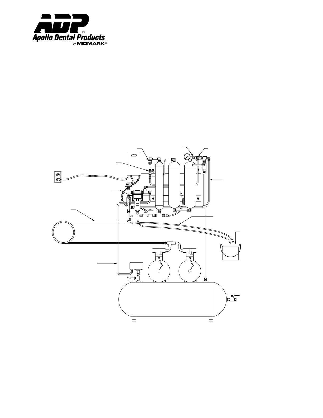
115VAC Outlet
Wet Air In From
Compressor
17' Intercooler
3/8" Tubing
DO NOT SHORTEN
Pressure Switch
Unloader Line
(5') 1/4" Tubing
Manual Purge
Valve Closed
Ultair
Filter
Flow Control
Valve
Air Tank
Check Valve
Purge Tank
Dryer Tank
Purge Tank
Moisture
Indicator
Dry Air Out To
Storage Tank
(5') 3/8" Tubing
Condensate
Drain Line
Condensate
Drain Canister
Warranty Information: (90 Days)
All ADP accessories are thoroughly inspected and tested in accordance with rigid specifications and standards. Our accessories are guaranteed against any
defective material and workmanship from the date of shipment; provided that the installation, operation, and maintenance is done in accordance with ADP
procedures as outlined in our Installation and Maintenance Guides. Warranty cards must be returned to ADP within ten days of installation to effect warranty.
No other warranties or guarantees, expressed or implied are made.
ADP’s obligation under the warranty is to provide parts for the repair or, at its option, to provide the replacement product (excluding labor). All special,
incidental and/or consequential damages are excluded. We will not issue credit for accessories without first attempting to correct the problem in the field.
Written notice of breach of warranty must be given to ADP within the warranty period. The warranty does not cove damage resulting form improper
installation or maintenance, accident or misuse. The warranty does not cover damage resulting from the use of cleaning, disinfecting or sterilizing chemicals
and processes. Failure to follow instructions provided in ADP’s Installation and Maintenance Guides may void the warranty.
Apollo Dental Products, Inc. • 245 W. Dakota Ave. • Clovis, CA 93612 • Technical Support
559/292-1444 • 800/233-4151 • Fax 559/292-1555 • www.apollodental.com
Page 1
AMI60393 Rev. 1/02
Page 2

Installation Instructions
Desiccant Air Dryer System
Technical Service - (800) 233-4151
Compressor Package Preparation:
1. Disconnect electrical power to air compressor at main circuit breaker panel.
2. Open the drain valve located on the underside of the air storage tank to expel all moisture which may have accumulated.
Close valve when completely purged.
3. Remove the existing compressor pressure switch and replace with the combination pressure switch/unloader provided
with the DAD system.
Note: Prior to disconnecting the pressure switch wires, label or mark the individual wires so that the
exact duplication of line and load connections is maintained when installing the new switch.
4. Remove compressor discharge line copper tubing connected between the discharge flex hose(s) and the entrance to the
air storage tank.
5. On twin head compressors, install discharge flex “T” block.
6. Remove the air storage tank check valve located at the storage tank entrance. The DAD system is equipped with a
storage tank check valve at the purge gauge assembly to facilitate manual purge operation.
Important: Failure to remove check valve may result in poor/abnormal performance.
Installing The DAD System (Refer to installation diagram on Page 1):
1. Install the 3/8” outlet copper tube connecting the DAD purge gauge/moisture indicator elbow compression fitting to the
entrance of the air compressor storage tank.
2. Install the 3/8” inlet copper tube connecting compressor discharge flex hose with compression tube fitting at the entrance
to the Ultair Filter on the DAD system.
Note: Use all copper tubing supplied to make loop. (See diagram on page 1).
3. Install the 1/4” copper tube from the elbow compression fitting at the outlet of the DAD Ultrair filter to the compression
fitting of the compressor pressure switch unloader valve.
4. Check to ensure the bypass valves are in correct operating position.
5. Plug the 115V line cord into a 115V receptacle. Reconnect electrical power, and restart compressor.
6. Check that the DAD purge gauge and compressor storage tank gauge pressurize, and the compressor shuts off at 100
PSI, and automatically unloads the DAD system.
7. Check all tubing connections on the DAD and compressor package for any leaks with soapy-water solution.
Important: Seal all leaks.
Page 2 AMI60393 Rev. 1/02
Page 3

Installation Instructions
Desiccant Air Dryer System
Technical Service - (800) 233-4151
Operation:
A. System Air Flow: The desiccant drying system acts to separate moisture from compressed air by directing the discharge air from
the compressor head(s) through a pre-cooler coil which cools the air and condenses moisture. The air then flows through a
coalescing filter which removes the condensed moisture, contaminants, and oil. The air then flows through the desiccant drying
chamber where the actual fine mist or moisture vapor removal takes place. The result is clean, cool, dry air returning to the
compressor storage tank and ultimately to the operatory (See Figure A on page 4).
B. Automatic Purge Cycle: The automatic purge cycle is the normal operation for the DAD system. During normal operation, the
small black manual purge valve handle should be horizontal (closed position). Once the storage tank air pressure reaches 100 PSI,
the compressor shuts off and the normal purge cycle begins; air stored in the purge tank is permitted to reflux (reverse) flow through
the drying chamber thus separating moisture absorbed by the silica gel (desiccant). Simultaneously, purge air and moisture are
expelled to the atmosphere by the solenoid unloader valve. Head pressure upstream of the unloader valve is released by the pressure
switch unloader valve (See Figure B on page 4).
C. Manual Purge Cycle: In the event the moisture indicator turns pink in color, indicating wet air, a manual purge cycle is needed to
regenerate the moisture saturated silica gel (desiccant) in the drying chamber. The manual purge cycle will allow air from the storage
tank and the purge tank to enter the drying chamber at a predetermined flow rate. This condition is typically due to an undersized
DAD system or poor maintenance of the coalescing filter element.
To operate, turn the small black manual purge valve (Indicated in illustration on page 1) handle to the vertical position. The manual
purge cycle provides additional drying capacity by allowing air from the storage tank to flow back through the drying chamber in
addition to regular purge air. This action should lower the moisture equilibrium level within the drying chamber. We suggest a
minimum of 12 hours running time per cycle and that the process be completed at night for a maximum of six consecutive nights. If
the moisture indicator remains pink, or visible moisture persists, the silica gel (desiccant) may need to be replaced. For the
replacement desiccant kit, order part #ACA85345 (See Figure C on page 4).
D. Bypass Mode: In the event of a component failure within the DAD system, the bypass valve circuit can be used so that compressor
operation can continue normally while performing maintenance. The DAD unit is placed in Bypass Mode by turning the (#1) Input
Valve to the “OFF” position, and the (#2) Exhaust Valve to the “ON” position. After the unit is placed in Bypass Mode, the 115V
power should be unplugged to avoid shock hazard. Periodic maintenance and/or component replacement can be performed on the
DAD unit while in Bypass Mode.
Maintenance:
The Apollo Dental Products’ DAD will give years of trouble-free, reliable service. However, certain parts do require periodic attention and
service. Failure to adequately service these parts will not only cause failure of your drying system, but will also result in unsatisfactory service
while the unit is running.
Ultrair Coalescing Filter:
The Ultrair filter removes 99.9997% of any oil discharged by the compressor. Any oil vapor or mist allowed to enter the drying chamber would
contaminate and make the drying system less efficient. The Ultrair filter contains an ultra-fine 0.01 micron coalescing filter element that
should be changed at least once a year.
Note: For best performance, change the intake filters on the compressor heads.
Condensate Draining:
All Apollo Dental Products’ DAD’s are equipped with two moisture removal components, the Ultrair coalescing filter and the silica gel
desiccant drying chamber. During the compressor shutdown automatic purge cycle, both the Ultrair coalescing filter and the drying chamber
release any condensate (oil and water) collected during the pump-up cycle. This condensate is expelled via a common drain line terminating
in the condensate drain canister. A considerable amount of moisture may be collected, this is normal. The condesate drain canister should be
emptied as required.
Page 3 AMI60393 Rev. 1/02
Page 4

Installation Instructions
Desiccant Air Dryer System
Technical Service - (800) 233-4151
Manual Purge
Valve Closed
Dryer Tank
Purge Tank
Purge Tank
FIGURE A - Pump Up Cycle
Manual Purge
Valve Closed
Dryer Tank
Purge Tank
Purge Tank
FIGURE B - Automatic Purge Cycle
Manual Purge
Valve Open
Dryer Tank
Purge Tank
Purge Tank
FIGURE C - Manual Purge Cycle
Manual Purge
Valve Open
#1
Infeed Bypass
Valve CLOSED
Dryer Tank
Purge Tank
Purge Tank
FIGURE D - Bypass Mode
#1 Closed, #2 Open
#2
Exhaust Bypass
Valve OPEN
Page 4 AMI60393 Rev. 1/02
Page 5

Installation Instructions
Desiccant Air Dryer System
Technical Service - (800) 233-4151
TROUBLESHOOTING
PROBLEM: Compressor motor runs, but will not build up pressure to 100 PSI.
Cause: Solenoid unloader valve or pressure switch unloader valve not closing when compressor runs.
Remedy: 1. Solenoid unloader valve or pressure switch unloader valve may be dirty or defective. Clean or replace.
Cause: Air leaks in system piping.
Remedy: 1. Check for leaks using soapy water solution. Repair any system piping air leaks.
2. Check voltage supply to DAD unit, verify 115 VAC between DAD terminal block terminals 1 and 2.
Cause: Blockage in air line.
Remedy: 1. Inspect all air lines for restrictions..
Cause: Leak in compressor unit.
Remedy: 1. Close the storage tank shut-off valve. With compressor running, check discharge line flex hose, pressure safety
valve, tank drain valve and all fittings for leaks using soapy water.
PROBLEM: Compressor cycles with no air being used.
Cause: Manual purge valve handle is in “ON” position (vertical).
Remedy: 1. Turn valve handle to normal “OFF” position (horizontal).
Cause: Leak in office air system.
Remedy: 1. Close the storage tank shut-off valve. If pressure is maintained at 100 PSI for 15-20 minutes, leak is in air system,
not in compressor.
Cause: Leak in compressor storage tank.
Remedy: 1. Storage tank check valve may be dirty or defective. Clean or replace.
2. Check for leaks at storage tank shut-off valve, pressure safety valve, tank drain valve, and all fittings attached to
storage tank using soapy water solution.
PROBLEM: Moisture indicator is pink.
Cause: Unloading system not functioning properly.
Remedy: 1. Check to see that the solenoid unloader valve closes when the compressor is pumping. Check 3/8 poly line to see if
air is coming out, if so repair or replace solenoid unloader valve.
2. Ensure that the solenoid unloader valve and pressure switch unloader valve open as soon as the compressor stops.
The purge tank gauge pressure should drop from 100 PSI to zero, this should take 1 minute / 45 seconds. See page
3 “Automatic Purge Cyle.”
3. If the solenoid unloader valve is suspected of malfunctioning, visually check for:
A) Leaking or dirty solenoid unloader valve seat.
B) Pressure switch unloader operation, adjust unloader tab screw if necessary.
Cause: Saturated Desiccant Drying Chamber.
Remedy: 1. Operate the drying system in the manual purge mode (See page 3). If after 1 week the system is not dry, replace the
silica gel (desiccant).
Cause: Leak in DAD unit.
Remedy: 1. Check for leaks using soapy water solution. Repair any system piping air leaks.
2. Check voltage supply to DAD unit. Verify 115 VAC between DAD terminal block terminals 1 and 2.
PROBLEM: Normal pressure in compressor storage tank, but no air supply to operatories.
Cause: Supply or bypass valve(s) in wrong position.
Remedy: 1. Check that the DAD system is either in the Normal Operating Mode, with the #1 valve open and #2 closed, or it is in
the Bypass Mode, with the #1 valve closed, and #2 open. Other combinations of open/closed valves will cause
malfunctions of the DAD and/or compressor.
Page 5 AMI60393 Rev. 1/02
Page 6

Installation Instructions
Desiccant Air Dryer System
Technical Service - (800) 233-4151
Pressure
Sensor
Switch
White
1
5
9
13
Relay
Red
DAD Control Box
1/2 A
Fuse
Black
Transformer
Black
4
8
14
Red
White
Yellow
Black
Black
Blue
24VAC
To
Solenoid
Valve
115VAC
Replacement Parts:
Description ACADAD5 ACADAD15
Filter, Drying Chamber (Airstone) PFM70300 PFM70300
Filter, Ultrair Coalescing (Complete) ACA85215 ACA85215
Filter, Ultrair Element (Replacement) PFM85210 PFM85210
Gauge, Purge Tank PGA70400 PGA70400
Kit, Drying Chamber w/ Desiccant Drying Material AAP90102 AAP90102
Kit, Moisture Indicator ACA85965 ACA85965
Kit, Silica Gel (Only) ACA85345 ACA85345
Valve, Check 3/8” PVV50515 PVV50515
Valve, Flow Control PVV50530 PVV50530
Valve, Manual Purge PVV50545 PVV50545
Valve, Pressure Switch Unloader ECS10450 ECS10450
Fuse EMS10930 EMS10930
Relay ETR10459 ETR10459
Transformer Assembly SEA95000 SEA95000
Pressure Sensor ECS10443 ECS10443
Valve, Bypass PVV50500 PVV50500
Page 6 AMI60393 Rev. 1/02
 Loading...