

Page 1
Page 2

No part of this document may be reproduced in any
form or by any means without the express written
consent of UPS Aviation Technologies, Inc.
II Morrow, UPS Aviation Technologies, and Apollo are
trademarks of UPS Aviation Technologies, Inc.
© 2001 by UPS Aviation Technologies, Inc. All rights
reserved.
Printed in the U.S.A.
UPS Aviation Technologies, Inc.
Consumer Products Division
2345 Turner Road, S.E.
Salem, OR 97302
U.S.A. Toll Free 800.525.6726
Canada Toll Free 800.654.3415
International 503.391.3411
FAX 503.364.2138
Visit our web page at http://www.upsat.com
Send comments about this manual by email to:
techpubs@at.ups.com
Page 3

Welcome ...
Welcome to a new era of aviation navigation. Once
again, II Morrow Inc. has set new standards in
features and ease of use for the general aviation
public. The Apollo GX-series of products are
unequaled in providing the features, level of
performance, and reliability that aviation users
require. The Apollo GX-series sets a precedent that
will be the standard to which all other avionics will be
compared.
The Apollo GX50 is a full-featured GPS receiver that
is IFR-certified for non-precision approach. The
GX55 GPS receiver is IFR-certified for en route
operation and designed to slide into your existing
Apollo Loran or Flybuddy GPS receiver mounting
tube. The GX60 combines the features of the GX50
with a revolutionary comm radio. The GX65 has the
comm features of the GX60, but is not IFR approach
certified and does not have the approach features.
You can be confident in knowing that you are the
owner of the state-of-the-art in aviation navigation
and communication. Our products are built to last
and to satisfy your navigation needs.
Read the Introduction and Getting Started sections of
the User’s Guide before you use your Apollo GX;
these sections will give you the “rules of the road.”
You can then refer to the other sections as a reference
for the power you have at your fingertips with the
most comprehensive navigation equipment available.
You will note that your User’s Guide may be missing
some sections. This guide serves the entire family of
Apollo GX products, but will only include the
sections that reflect the features available in the
product that you purchased. If you have an interest in
the features and operation of the other models, see the
section on Ordering Information.
i
Page 4

History of Revisions
Revision Date Software Ver. Manual P/N
January 1998 2.1 560-0961-00
June 1998 2.2 560-0961-01
January 1999 2.2 560-0961-01a
March 1999 3.0 560-0961-02
July 2001 3.3 560-0961-03
Ordering Information
To receive additional copies of the Apollo GX50/55/60/65
manuals order the following part numbers:
User’s Guide 560-0961-xx
Approach User’s Guide Insert 560-0928-xx
GX60/65 Comm User’s Guide Insert 560-0963-xx
User’s Guide Binder (1") 560-9000
User’s Guide Binder (3/4”) 560-9002
User’s Guide Binder (1-1/2”) 560-9005
GX50/60/65 Installation Manual 560-0959-xx
GX50/60/65 SW Ver 3.3 Installation Manual
Upgrade Supplement 561-0275-xx
A-33 Antenna Installation Guide 560-0949-xx
GX55 Installation Manual 560-0960-xx
GX50 Quick Reference 561-0238-xx
GX55 Quick Reference 561-0237-xx
GX60/65 Quick Reference 561-0236-xx
GX65 User’s Guide Insert 561-0256-xx
ii
Page 5

Important Notice
The Global Positioning System (GPS) is operated by the United States Department of Defense which is solely
responsible for the accuracy, daily operation, and maintenance of the satellite constellation. System accuracy is
affected by the Department of Defense’s Selective Availability (SA) and the Dilution of Precision (DOP) attributed to
poor satellite geometry.
Due to implementation of Selective Availability by the United States Department of Defense (DoD), all GPS receivers
may suffer degradation of position accuracy. The DoD has stated that 95% of the time horizontal accuracy will not be
degraded more than 100 m and 99.9% of the time accuracy will not be degraded more than 300 m.
Installations of TSO C-129a authorized Apollo GX50/60’s and TSO-C-129 authorized GX55’s may be approved for
supplemental navigation only. The Apollo GX50, GX55, or GX60 may be used as the primary navigation data
display, however, other means of navigation appropriate to the intended route of flight must be installed and
operational. It is not required that these other systems be monitored.
FCC Notice
This equipment has been tested and found to comply with the limits for a Class B digital device, pursuant to part 15 of
the FCC Rules. These limits are designed to provide reasonable protection against harmful interference during
residential use. Operation is subject to the following two conditions: (1) this device may not cause harmful
interference, and (2) this device must accept any interference received, including interference that may cause
undesired operation. This equipment generates, uses and can radiate radio frequency energy and, if not installed and
used in accordance with the instructions, may cause harmful interference to radio communications. However, there is
no guarantee that interference will not occur in a particular installation. If this equipment does cause harmful
interference to radio or television reception, which can be determined by turning the equipment off and on, the user is
encouraged to try to correct the interference by one or more of the following measures:
Reorient or relocate the receiving antenna.
•
Increase the separation between the equipment and receiver.
•
•
Connect the equipment into an outlet on a circuit different from the one the receiver is connected.
•
Consult the dealer or an experienced radio/TV technician for help.
Changes or modifications to this equipment not expressly approved by II Morrow Inc. could void the user’s authority to
operate this equipment.
Canadian Notice
This Class B digital apparatus meets all requirements of the Canadian Interference-Causing Equipment Regulations.
Cet appareil numérique de la classe B respecte toutes les exigences du Règiement sur le matériel brouiileur du
Canada.
iii
Page 6
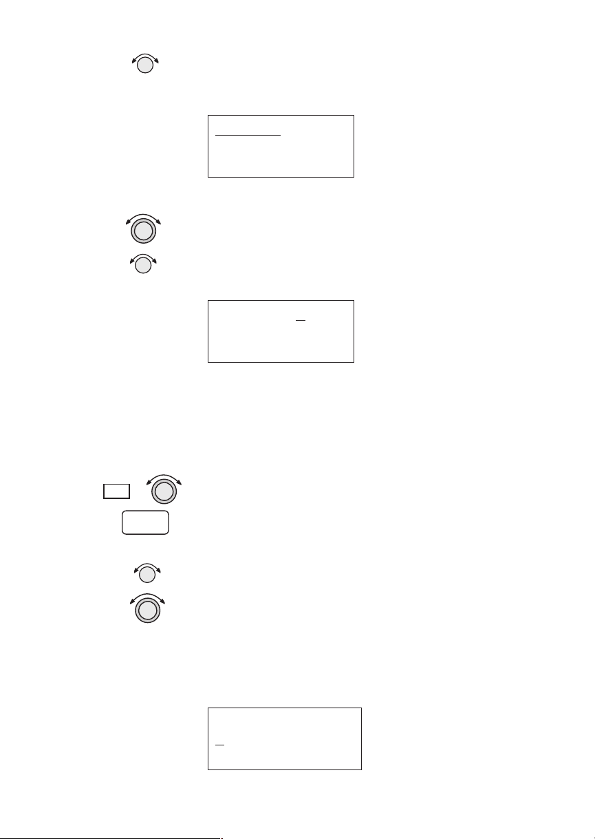
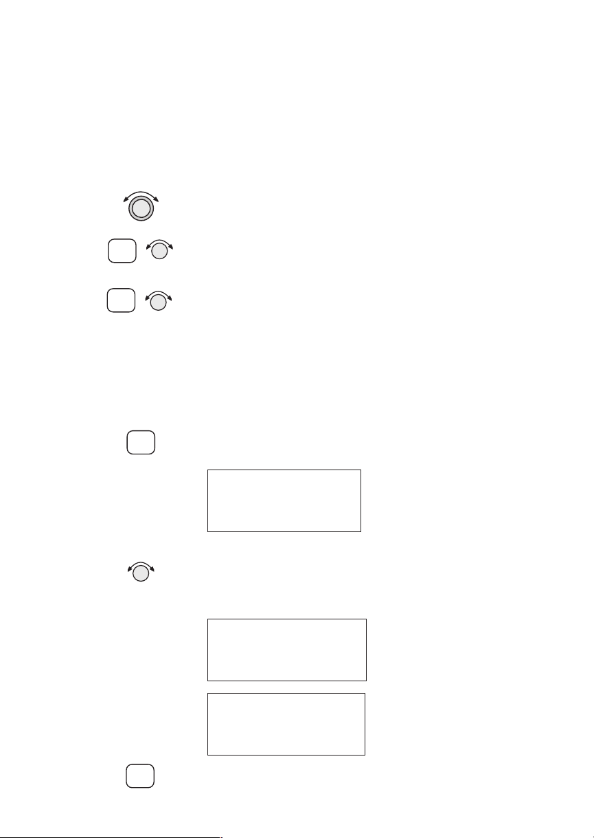
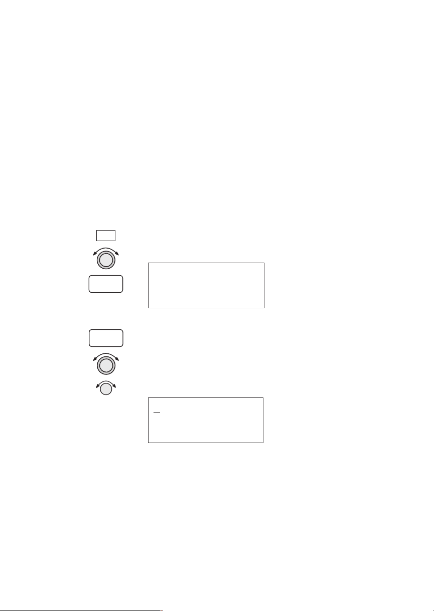
Conventions
f
unciato
The SMALL knob is the smaller, inner knob of the two
concentric rotary knobs used to look at or change
information on the display. When only the
is shown next to an example, turn the SMALL knob.
The LARGE knob is the larger, outer knob of the two
concentric rotary knobs used to look at or change
information on the display. The
shows both of the concentric knobs. Turn the LARGE,
outer knob when this graphic is shown next to an
example.
ENTER Text in all caps and bold indicates the key to press.
A graphic key on the side of the page refers to the key
you should press for the given example. There are two
types of keys: hard keys and smart keys.
LARGE knob graphic
SMALL knob
NAV
A “hard” key is a permanent key on the right side of
the front panel. The
NAV key example shown here is a
“hard” key.
MSG
The “smart” keys are five small keys below the
display. The key label is shown above the key on the
display and may change depending on the function
you are using. Press the key below the label to access
the function.
Text in a display example with an underline indicates
the text will flash. In the example below, the field
labeled “01:23” is underlined to indicate that it is
flashing and ready for editing. The flashing characters
on the display are changed by turning the
SMALL
knob. The GX55 is shown below as an example for
Flashing
ield
the control locations.
GPS
ete SLE
1.006
01:23
“
NAV
Brg 126 123nm
MSG
Smart Key
Ann
Smart Keys
r
iv
SYSFPLDB
PowerHardKeys
POLLOAGX55
NRST INFO SEL
D
ENTERMAP
Small, Inner Knob
Large, Outer
Knob
OFF-ON
Page 7

Table of Contents
Table of Contents
Introduction ..............................................1-1
Apollo GX Features .................................1-1
Display ..............................................1-2
External Annunciators ...............................1-3
Controls..............................................1-3
Keys .................................................1-4
Hard Keys ............................................1-4
“Smart” Keys .........................................1-5
Map Function Smart Keys ..............................1-6
Communications Radio Mode Smart Keys (GX60/65) .........1-8
Apollo GX Features .......................................1-9
Getting Started ...........................................2-1
Power On ............................................2-1
Select a Waypoint......................................2-1
Finding a waypoint by name ..........................2-1
Sorting waypoints by selected characters.................2-2
Looking at all waypoints in a database ..................2-3
Duplicate Identifier, City, or Facility Names .............2-4
Waypoint Information..................................2-4
Storing a Waypoint ....................................2-5
Finding a Nearest Waypoint.............................2-6
Flying Direct-To a Waypoint ............................2-7
Create a Flight Plan ....................................2-8
Activating a Flight Plan.................................2-9
Using the Moving Map ................................2-10
Navigation Basics .........................................3-1
About the Navigation Function ..........................3-1
About the Navigation Function Displays ..................3-1
Nav Home Page .......................................3-1
Autonav ..............................................3-2
Relative Bearing Indicator ...............................3-3
Nav Pages ............................................3-3
Estimated Time En Route (Ete) .......................3-4
Bearing (Brg) .......................................3-4
v
Page 8

Table of Contents
Range (Rge) ........................................3-4
Course Deviation Indicator (CDI) and Distance Off Track. 3-5
TO/FROM Indicator ................................3-6
Desired Track (Dtk) .................................3-6
Leg (FROM-TO) Distance ...........................3-6
Track (Trk) Angle ...................................3-7
Track Angle Error (Tae)..............................3-7
Ground Speed (GS) .................................3-7
Minimum Safe Altitude (MSA) ........................3-8
Minimum En Route Safe Altitude (MESA) ..............3-8
Flight Time ........................................3-9
Time UTC .........................................3-9
Estimated Time of Arrival (ETA) ......................3-9
Nearest Waypoint & Airspace Search......................3-9
Controlled Special Use Airspace.........................3-13
Altitude Assist (VNAV) ...............................3-14
Parallel Track Offset ..................................3-19
GPS Position ........................................3-21
Countdown Timer ....................................3-22
Arc Assist ............................................3-23
Waypoint Distance Page ...............................3-25
Waypoint ETE Page ..................................3-25
From-To-Next Waypoint ETA Page.....................3-25
From/To/Next Waypoint ..............................3-26
Creating FROM/TO/NEXT Waypoints ...............3-26
Placing the TO Waypoint on Hold ....................3-30
Using Direct-To......................................3-31
Direct-To Examples...................................3-32
Center the CDI ....................................3-32
Enter a New Waypoint into a Flight Plan ..............3-33
Direct-To OBS.......................................3-35
Turn Anticipation ....................................3-36
Standard Turn Operation............................3-36
Wind and Turn Anticipation .........................3-37
GPSS ...............................................3-37
Standard GPSS Operation ...........................3-37
vi
Page 9

Table of Contents
Approach GPSS Operation ..........................3-38
GPSS Rules .......................................3-38
Tuned Station........................................3-39
Tuning to a VOR...................................3-39
Tuning to a Localizer ...............................3-40
Moving Map Functions ....................................4-1
Full Screen Map.......................................4-1
Controls..............................................4-2
Waypoint Type Keys.................................4-2
Waypoint List Keys ..................................4-2
Waypoint Scan Key..................................4-3
Map Scale..........................................4-3
Map and Nav Info .....................................4-3
Map Setup............................................4-4
Route Line .........................................4-4
Map Orient.........................................4-5
Map Reference ......................................4-6
Identifier and Waypoint Type Selection .................4-6
Track History.......................................4-8
Airspace Setup .....................................4-10
Airspace Buffers ....................................4-11
ATC Ring Selection ................................4-12
Airspace Selections .................................4-12
Search and Rescue ....................................4-14
Search and Rescue Map Description ...................4-14
Grid Line Display ..................................4-15
US Grid Type .....................................4-15
Basic Grid Type....................................4-16
Search and Rescue Map Setup Page ...................4-16
Set the SAR Position (Basic Grid Type) ................4-18
Selecting A Pattern .................................4-20
Parallel Line Search Pattern..........................4-21
Creeping Line Search Pattern ........................4-23
Expanding Square Search Pattern.....................4-26
Mark A Position....................................4-28
Create A User Waypoint By US Grid ..................4-29
vii
Page 10

Table of Contents
Fly Direct To A US Grid ............................4-30
Create a User Waypoint By Basic Grid .................4-30
Fly Direct To A Basic Grid...........................4-32
Setting Up A Search Pattern..........................4-32
Waypoint Database........................................5-1
Waypoint Information..................................5-1
Available Waypoint Information .........................5-1
Getting Information About A Waypoint ...................5-3
Airport Info Pages .....................................5-5
Create User Waypoint by Lat/Lon ........................5-9
Create User Waypoint by Radial/Distance ................5-10
Update User Wpt with Present Pos ......................5-12
Delete User Waypoint .................................5-12
Modify User Waypoint ................................5-13
Creating Waypoint Comments..........................5-14
Deleting Waypoint Comments..........................5-15
Update User Waypoint ................................5-16
Datacard ............................................5-16
RNAV Waypoints.....................................5-16
Flight Plan Functions .....................................6-1
Flight Plan Pages ......................................6-1
Creating a Flight Plan ..................................6-2
Flight Plan Sequencing .................................6-5
Flight Plan Leg Information.............................6-6
Manual Leg Activation .................................6-9
Flight Plan Editing ...................................6-10
Flight Plan Options ...................................6-14
Activate ...........................................6-14
Rev Activate .......................................6-15
Reactivate .........................................6-15
Rename...........................................6-15
Copy Plan.........................................6-16
Estimated Ground Speed ...........................6-16
Clear Waypoints ...................................6-17
Reverse Flight Plan .................................6-17
Estimated Fuel Flow................................6-17
viii
Page 11

Delete Plan........................................6-18
Hold .............................................6-18
Holding Patterns (GX50/60) .........................6-19
Continue..........................................6-21
Load Approach (GX50/60 Only)......................6-22
Change Approach (GX50/60 Only) ...................6-22
Unload Approach (GX50/60 Only)....................6-22
Enable Approach (GX50/60 Only) ....................6-23
Disable Approach (GX50/60 Only)....................6-23
Destination Waypoint Information ......................6-23
Flight Plan Comments ................................6-23
Saving an Active Flight Plan............................6-24
System Functions .........................................7-1
Navigation Information.................................7-1
Autonav Time ......................................7-1
Navigation Mode Programmable and Autonav Pages......7-2
Customizing Navigation Pages ........................7-2
Selecting Autonav Pages ..............................7-4
Restoring Default Nav Pages ..........................7-4
Lat/Lon Units ......................................7-4
Setting Units of Measurement .........................7-6
Magnetic Variation ..................................7-7
Flight Timer Trigger.................................7-8
Direct-To Entry Options .............................7-8
CDI Scaling .......................................7-10
System Information ...................................7-11
Date and Time.....................................7-11
Software Version ...................................7-12
Fuel Measure Units (GX50/60 Only) ..................7-13
Barometric Measure Units (GX50/60 Only) ............7-14
Test Display .......................................7-14
Display Brightness..................................7-14
Viewing Owner Information .........................7-15
Editing Owner Information ..........................7-16
GPS Sensor..........................................7-17
Miscellaneous Sensors ................................7-20
ix
Page 12

Table of Contents
Encoding Altimeter ...................................7-20
Air Data Info.........................................7-21
Air Speed .........................................7-21
Air Temperature ...................................7-21
Altitude and Rate of Climb...........................7-21
Heading and Turn Rate .............................7-21
Wind Direction and Speed...........................7-22
Fuel Info ............................................7-22
Fuel Endurance....................................7-22
Range, Burn Rate, and Fuel Used .....................7-22
Right Engine Fuel ..................................7-23
Left Engine Fuel ...................................7-23
Total Fuel.........................................7-23
Fuel Measure ......................................7-24
Message Function .........................................8-1
New Messages ........................................8-2
Old Messages .........................................8-2
Messages .............................................8-3
Approach Basics (GX50/60) .................................9-1
Introduction ..........................................9-1
En Route...........................................9-1
Approach Transition .................................9-2
Approach Active.....................................9-2
Approach Transition .................................9-2
Waypoint Arrival Alert ...............................9-2
Approach Procedure....................................9-5
En Route Operations ...................................9-5
Load a Destination Airport............................9-6
Load Approach Information...........................9-7
Approach Transition Operation (Enabling Approach) .......9-8
Approach Active Operation.............................9-11
Missed Approaches....................................9-13
Canceling An Approach ...............................9-15
Repeating an Approach ................................9-16
Selecting a Different Approach..........................9-17
Direct-To ...........................................9-18
x
Page 13

Table of Contents
Manually Selecting a Flight plan Leg ....................9-19
Flight Plan Waypoint Sequencing .......................9-20
Procedure Turns......................................9-21
Procedure Turn at FAF................................9-22
Holding Patterns .....................................9-24
DME Arcs (Arc Assist).................................9-26
Vector to Final .......................................9-27
Navigating to a DME .................................9-28
RAIM...............................................9-29
RAIM Nav Page (GX50/60 Only) .......................9-33
Emergency (Alternate) Approach........................9-35
Clear Waypoints ...................................9-35
Fly Direct-To a Nearest Airport ......................9-36
Set New Approach..................................9-36
Approach Examples.......................................9-37
Approach Example 1 - Straight In .......................9-39
Approach Example 2 - Holding at IFAF ..................9-44
Approach Example 3 - Missed Approach..................9-51
Approach Example 4 - VOR Reference ...................9-56
Manual Flight Plan Leg Selection Example ...............9-61
Approach Example 5 - DME Arc .......................9-63
Approach Example 6 - Procedure Turn 1 .................9-66
Approach Example 7 - Procedure Turn 2 .................9-68
Using the LOC-DME Waypoint ........................9-69
Approach Notes ..........................................9-77
Comm Radio Operation ...................................10-1
Power On/Off ........................................10-1
Volume .............................................10-1
Selecting Frequencies ..................................10-2
Comm Mode Map Display .............................10-3
Frequency Monitoring.................................10-3
Recalling a Frequency .................................10-4
Nearest Frequency .................................10-6
INFO Frequency ..................................10-6
Destination, TO, and FROM Frequencies..............10-6
Auto Stored Frequencies (Auto) ......................10-6
xi
Page 14

Table of Contents
User Stored Frequencies.............................10-7
Weather Channels..................................10-7
Emergency Channel ................................10-8
Intercom Function ....................................10-8
Stuck Mic ...........................................10-9
Com Radio System Information (GX60/65 Only) ..........10-9
RF Signal Strength ................................10-10
Noise Level ......................................10-10
Intercom Squelch Level Adjustment ..................10-10
Transmit Mic Selection ............................10-11
Intercom Level....................................10-11
Sidetone Level Adjustment ..........................10-12
Headphone Level Adjustment ........................10-12
Start Up Displays.........................................11-1
Startup Bypass .......................................11-1
Quick Comm (GX60/65 Only)..........................11-1
Comm Radio Test (GX60/65) ..........................11-1
Owner Message ......................................11-2
Memory Tests ........................................11-2
Database Message ....................................11-5
Seed Position ........................................11-5
Entering a Seed Position ...............................11-5
IFR Output Tests .....................................11-8
Checking GPS Signal Strength ........................11-11
Flight Simulator .........................................12-1
About the Flight Simulator .............................12-1
Removing and Replacing the Apollo GX..................12-2
Starting the Flight Simulation ..........................12-3
Flight Simulator Operations ............................12-4
Troubleshooting .........................................13-1
Contacting the Factory ................................13-1
To Ensure Trouble Free Operation ......................13-2
Battery Replacement ..................................13-2
If You Have A Problem ................................13-2
GPS Navigation ..........................................14-1
Glossary ................................................15-1
xii
Page 15
Introduction
This guide describes the operation of the Apollo GX
line of products. The GX50 and GX55 are GPS
receivers. The GX60/65 models combine the GPS
receiver with a VHF comm radio in a single package.
Apollo GX Features
The Apollo GX products are high performance GPS
products with a high resolution moving map display
configured in a 2 inch high by 6.25 inch wide
standard package. The Apollo GX’s use a powerful,
accurate 8-channel GPS engine designed specifically
for high performance aviation use. The 160 by 80
pixel electroluminescent display uses an automatic
intensity control to keep it easily readable in all
conditions from direct sunlight to the dark of night.
Information
Display
Navigation
Mode
Waypoint
Info
Mode
Select
Introduction
PowerPhotocell Nearest
Large, Outer
Knob
GPS
ete SLE 01:23
1.006
Brg 126 123nm
MSG
Smart Key
Annunciator
Apollo GX Front Panel Description
A wealth of easy to use features serve the needs of
today’s demanding aviation requirements. The large
waypoint database has information about airports,
VORs, NDBs, intersections, and special use airspaces
that makes the Apollo GX an encyclopedia of
aviation. It’s what you’d expect from II Morrow, the
first to provide a database in a general aviation
navigation aid. The database can be updated by
simply changing the removable data card in the front
of the unit. The database can also include 500 custom
waypoints created by the user. Thirty flight plans can
“
SYSFPLDB
Smart Keys
Slot
NAV
Mode
POLLOAGX55
NRST INFO SEL
D
ENTERMAP
Datacard
Direct ToMap
EnterDatacard
OFF-ON
Ejector
Small, Inner
Knob
1-1
Page 16

Introduction
be saved with up to twenty legs for setting up custom
tailored routes. The detailed Navigation information
displays are also customizable and can be set to
automatically scroll through the desired information.
The Nearest/Emergency Search feature, invented by
II Morrow (UPS Aviation Technologies), makes it
easy to react to an emergency or change your active
flight plan.
GX55
The GX55 is designed to be simple slide-in,
pin-compatible replacement for panel-mounted
Apollo Loran and Flybuddy GPS receivers. The
GX55 connectors and antenna footprint are the same
as the Apollo Loran and Flybuddy GPS receivers.
The GX55 is TSO-C129 Class A2 authorized for IFR
en route and terminal operation.
GX50
The Apollo GX50 GPS receiver possesses all of the
performance features of the GX55, plus more. The
GX50 is TSO-C129a Class A1 authorized for IFR
non-precision approach operation. The GX50 uses
the same tray size, but different connections on the
back to allow for approach capabilities.
GX60
The Apollo GX60 combines the physical package of
the GX50 GPS receiver with a revolutionary VHF
Comm transceiver. All of this without the
requirement for external cooling.
GX65
The Apollo GX65 possesses the same features as the
GX60, except it is not certified for IFR approaches.
Display The display is a 160 by 80 pixel electroluminescent
graphic display. A photocell is located in the top left
corner of the front panel display. The photocell
automatically controls the light intensity of the
display from low brightness at night to high
brightness during daylight operation.
1-2
Page 17

Introduction
External Annunciators
When external indicators are installed, the Apollo GX
will also provide an external indication when Parallel
Track (PTK) is activated or a Message (MSG) is
received. The GX50/60 also have external
annunciator controls for OBS/Hold and Approach
Active. “Hold” refers to suspending waypoint
sequencing.
Controls The Apollo GX uses a variety of controls to manage
the features. The controls include a power knob,
dual-concentric knobs (called
LARGE and SMALL),
hard keys, and “smart” keys.
Power Knob
The knob on the top right side of the Apollo GX
controls power on/off. Rotate the knob clockwise
(CW) past the detent to turn the power on. Rotate the
knob fully counterclockwise to turn the power off.
Full rotation and the push-pull capabilities are only
used in the GX60/65.
Power/Volume/Squelch Knob(GX60/65)
The knob on the right side of the GX60/65 controls
power on/off, volume, and squelch test. Rotate the knob
clockwise (CW) past the detent to turn the power on.
Continue rotating the knob to the right to increase
speaker and headphone amplifier volume level. Rotate
the knob to the left to reduce the volume level. Pull the
knob out to disable automatic squelch.
SMALL and LARGE Knobs
The dual concentric knobs on the right side of the
front panel are used to select pages, edit characters
and values, or other options. The
the cursor and the
SMALL knob changes characters.
LARGE knob moves
Either may change pages depending on the function.
1-3
Page 18

Introduction
Keys There are two types of keys that allow you access to
the functions in your Apollo GX: permanent “hard”
keys and displayed “smart” keys. Seven back lighted
permanent keys are used to reach the functions or
perform other operations of the Apollo GX. The
“smart” key labels are shown on the bottom of the
display. There are two categories of “smart” keys:
those available for the Map function and those
available at all other times. Press the key below the
label to use the displayed function. Press a function
key once to go to the last page viewed or twice to go to
its “home” page.
Hard Keys The “Hard” keys are the easy-touch, black, rounded
keys with white lettering on the right side of the
display. These keys include,
MAP, Direct-To, and ENTER.
NAV, NRST, INFO, SEL,
NAV
NRST
INFO
SEL
NAV
NRST INFO SEL
D
ENTERMAP
NAV (Navigation)
Press the
NAV key to reach the navigation functions.
Press twice to go to the “top” page.
NRST (Nearest Waypoint)
The Nearest Waypoint (Emergency) mode displays
the closest waypoints to your position.
INFO (Information)
The Info function accesses supplementary
information about a waypoint. Press
INFO a second
time to return to the previous display.
SEL (Select)
The SELECT key activates editing or the selection of
options. Editing is active on the items that flash on
the display. Press
SEL a second time to deactivate
selection.
1-4
Page 19

Introduction
MAP (Graphic Moving Map)
MAP
The Map key starts the Moving Map function. The
entire display is used as a graphic map display.
DIRECT-TO
DIRECT-TO key is used to define a direct course
D
The
from your present position to a waypoint. Press once
to select a waypoint. Press twice to enter an OBS
desired track To or From the current active waypoint.
ENTER
The
ENTER
ENTER key enters and saves the information
flashing on the display. If the
ENTER key is not
pressed after editing, any changes made are not saved.
In the GX60/65, the
ENTER key flip/flops the Active
and Standby frequencies.
“Smart” Keys The Apollo GX uses “smart” keys to provide custom
controls for specialized functions. Five small
unlabeled keys are located below the display. The
labels appear on the display and can change to give
extra controls for the active function, such as in the
MAP function. You can always press the
NAV key to
go back to the Navigation function and view the
normal “smart” keys.
MSG
DB
FPL
MSG (Message)
Press the
MSG key to reach the Message functions.
The MSG annunciator will flash when a new
message is provided. Press the
MSG key a second time
to return to the previous display after all new
messages have been viewed. The
MSG key will remain
highlighted when a message remains.
DB (Database)
The Database key provides access to the waypoint
database.
FPL (Flight Plan)
The Flight Plan key takes you to the flight planning
function where you can create, edit, and control your
flight plans.
1-5
Page 20

Introduction
SYS
SKIP
SYS (System Mode)
Press the
SYS key to reach the System mode functions.
System mode is used to make system level
adjustments and modify Nav function displays.
SKIP (Start-Up Option)
Press the
SKIP key during the start-up procedure to
bypass the start-up tests. This is for emergencies as
the IFR tests must be completed to allow IFR flight.
Map
Function
Smart Keys
APT
VOR
INT
NDB
USR
APT
APT
The Moving Map function uses several “smart” keys
to allow you to declutter the map, find waypoint
information, and setup your map information.
Map Waypoint Keys
APT, VOR, INT, NDB, & USR
The map waypoint “smart” keys are present when the
Moving Map pages are displayed. Press the “smart”
key to control the display of the waypoint type. There
are three selections possible: waypoint identifier and
location symbol, location symbol only, and off.
Pressing the “smart” key subsequent times will
control which selection is made. Map waypoint
choices are: Airport (APT), VOR, NDB, Intersection
(INT), and User (USR).
A solid, reversed waypoint type annunciator above the
“smart” key means the waypoint identifier and
location symbol will both be displayed.
A bold outline of the waypoint type annunciator will
show only a symbol on the waypoint location.
1-6
NDB
2
A thin outline around the waypoint type means that it
is turned off and no information for that waypoint
type will be displayed on the map.
Waypoint LIST Key
Each press of this key scrolls through the available
“smart” keys.
Page 21
SCAN
Introduction
Waypoint SCAN Key
When the
Moving Map display, turning the
SCAN key is active (highlighted) in the
LARGE knob will
move between the nearest airports. You can then press
INFO to view information about that airport. In an
emergency press
to the highlighted airport. Press the
return the
DIRECT-TO and ENTER to fly direct
SCAN key again to
LARGE knob to normal operation.
Map Setup Keys
The Map Setup page displays three “smart” keys that
provide a short cut for customizing your moving map.
Route Line:On
Map Orient:DTK
Map ref:Plane·
RTE
ORI
REF
RTE ORI REF
Route
Line
Map
Orientation
Map
Reference
The Route Line “smart” key toggles between On and
Off. See page 4 for more details.
The Map Orientation “smart” key toggles between
Desired Track (DTK), Track, and North. See page 5
for more details.
The Map Reference “smart” key toggles between
Plane and Destination (Dest) as the moving map
center point. See page 6 for more details.
1-7
Page 22

Introduction
Communicati
ons Radio
Mode Smart
Keys
(GX60/65)
COM
<>
RCL
MON
The Recall (RCL), Monitor (MON), Memorize
(MEM), and
the GX60/65 after the
FLIP/FLOP (<->) keys are available in
COM soft key has been pressed.
COM (GX60/65)
Press the
COM key to operate the Communications
radio functions.
Flip/Flop (GX60/65)
Press the
FLIP/FLOP key to switch between the active
(left-most) and standby (right-most) frequency while in
the Com function. You may use an optional external
FLIP/FLOP key for the same operation as the front panel
control. Switching between frequencies is disabled while
you are transmitting or editing in any function.
RCL (Recall) (GX60/65)
Press the
RCL key to recall frequencies stored in the
database.
MON (Monitor) (GX60/65)
Press the
MON key to listen to the Standby frequency.
When the Active frequency receives a signal, the
GX60 will automatically switch to the Active
frequency.
1-8
MEM
XIT
MEM (Memorize) (GX60/65)
Press the
MEM key to store the current Standby
frequency.
XIT (Exit) (GX60/65)
The
XIT key will appear on the far left of the display,
in the
MSG key position, if the COM key has been
pressed to allow use of the radio during startup
testing. Press the
sequence, or wait for test completion. The
XIT key to return to the start-up
XIT key
will disappear when testing is complete.
Page 23

Apollo GX Features
Apollo GX Features
Navigation Features
30 Reversible Flight Plans of up to 20 Legs with Automatic
Sequencing
500 User-Defined Waypoints
Nav Displays
Lat/Lon
Bearing and Distance
Ground Speed and Track Angle
Desired Track and Distance
Internal CDI Display
160 pixel wide by 80 pixel high electroluminescent display with
moving map
Automatic Display Intensity Control
User-Selectable Nav Displays
User-Definable Distance and Speed Settings:
nm and km (distance)
knots
Clock and Countdown Timer
Auto/Manual Magnetic Variation Settings
Direct-To Nav Function
Parallel Track
Nearest Waypoint Search
Internal Database of Airports, VORs, NDBs, Intersections,
Frequencies, Airport Info, and controlled and special use
airspace
GPS Receiver Performance Specifications
8-Channel Parallel GPS Receiver
Frequency 1575.42 MHz L1, C/A code
Sensitivity (acquisition) -135 dBm
Sensitivity (drop lock) -142 dBm
Dynamic range > 20 dB
Lat/Lon position accuracy
15 meters RMS accuracy
25 meters, SEP, without SA
100 meters 2 DRMS with SA
Velocity 999 knots maximum
Acceleration 4G maximum
TTFF (time to first fix)
25 sec. typ. with current almanac, position, time, and ephemeris
55 seconds typical with current almanac, position, & time
Reacquisition 2.5 seconds typical
Position update interval 1 second typical
Datum WGS-84
1-9
Page 24

Apollo GX Features
Electrical
Input voltage
10 VDC to 40 VDC, reverse polarity protected
Input current (GPS navigation input)
500 mA typical, 750 mA max at 13.75 VDC
250 mA typical, 375 mA max at 27.5 VDC
Input current (comm input - GX60/65 only)
270 mA typical, 2A max at 13.75 VDC, receive
130 mA typical, 900 mA max at 27.5 VDC, receive
2.1A typical, 3.2A max at 13.75, transmit
1.0A typical, 1.4A max at 27.5 VDC, transmit
Input power (GPS navigation input)
7 watts typical
Input power (comm input - GX60/65 only)
3.7 watts typical, receive
28 watts typical, transmit
GX50 and GX60/65 Avionics Outputs
CDI L/R deviation ±150 mv full scale
TO/OFF/FROM flag ±250 mv, TO/FROM indication
Nav valid flag +300 mv for valid indication
Nav superflag 400 ma source
VDI up/down ±150 mv
VDI valid flag +300 mv
VDI superflag 400 ma source
Annunciators
MSG (message)
PTK (parallel track)
OBS/HLD (waypoint sequencing hold)
APPRCH (approach enabled)GX50/60 only
ACTIVE (approach active) GX50/60 only
GX50/60 only
GX55 Avionics Outputs
CDI L/R deviation ±150 mv full scale
TO/OFF/FROM flag ±250 mv, TO/FROM indication
Nav valid flag +300 mv for valid indication
Annunciators
MSG (message)
PTK (parallel track)
Avionics Inputs
Serial
Frequency flip/flop (GX60/65 only)
Waypoint Sequence (GX50/60 only)
1-10
Page 25

Apollo GX Features
Serial Interface
2 RS-232 for GX50/60/65
1 RS-232 for GX55
Physical Specifications
Height: 2.0 inches (5.08 cm)
Width: 6.25 inches (15.88 cm)
Depth: 11.125 inches (28.26 cm) behind panel, including
mounting frame and connectors
Weight (with mounting frame):
GX50 and GX55 - 2.6 pounds (1.179 kg)
GX60/65 - 3.1 pounds (1.409 kg)
Environmental Specifications
Operating temperature -20ºC to +55ºC
Storage temperature -55ºC to +85ºC
Temperature variation 2ºC per minute
Humidity 95% at 50ºC for 6 hrs (2 day
cycle)
Maximum altitude 55,000 feet
Cooling Not required
VHF Comm Features (GX60/65)
760 channels
Frequency range of 118.000 to 136.975 MHz
Active and standby frequency display
Transmit status indicator
Stuck mic time-out
Frequency monitor function - listen to Standby frequency
while monitoring Active frequency for any activity
Weather channels - National Weather Service channels
Built-in intercom function
Frequency memory and recall functions
from navigation data base
ten last used
ten user stored
Two microphone inputs
12 watt audio amplifier
(not available in all databases)
1-11
Page 26

Apollo GX Features
VHF Comm Receiver Performance Specifications (GX60/65)
Class D
Frequency range - 118.000 to 136.975 MHz, 760 channels
Sensitivity
1 microvolt (2 microvolt hard) for 6 dB S+N/N
30% modulation at 1000 Hz
Selectivity
<6 dB variation at ±22 kHz
Speaker audio output level
12 watts into 4 ohms, 8 watts into 8 ohms
Headphone audio output level
280 mW into 100 ohms, 120 mW into 500 ohms
Distortion - <5% at rated output at 1000 Hz
AGC characteristics
<3dB variation in audio output from 5 to 100 mV input,
15% to 90% modulation
Squelch control - Automatic with manual override
VHF Comm Transceiver Performance Specifications (GX60/65)
Class 4
Output Power
8 watts minimum carrier at > 12 VDC
6 watts minimum at 10 VDC (transmit is locked out below
9 VDC input)
Modulation capability
85% with 100 mv to 1000 mv rms microphone input at
1000 Hz
Duty cycle 100%
Stuck mic time out
35 second time-out, reverts to receive
TSO Authorizations
GX50
TSO C129A A1
GX55
TSO C129 A2
GX60
TSO C129A A1
TSO C128
TSO C37d
TSO C38d
GX65
TSO C129A A2
TSO C128
TSO C37d
TSO C38d
Features and specifications subject to change without notice.
1-12
Page 27

Getting Started
Getting Started
This section explains how to get started using your
Apollo GX. Information in this section explains how
to:
Select a waypoint
·
Store waypoints
·
Find a Nearest Waypoint
·
Fly Direct-To a waypoint
·
Create a flight plan
·
Activate a flight plan
·
Use the Moving Map
·
It is necessary to enter a seed position and the current
time the first time you turn the unit on. This should
have been done when your unit was installed. So, you
won’t have to set it again unless the unit has been
moved several hundred miles with the power off.
Power On Turn the Power knob clockwise to switch the unit on.
The startup screen, testing, position, and database
information shows on the display for several seconds
and then will go into the Navigation function.
Select a
Waypoint
DB
ENTER
You can search for a waypoint character by character,
sort through the database by selecting the first few
characters of the identifier to simplify the search, or
look at every waypoint in order. You can search for
waypoints by identifier or the city/facility name.
Finding a waypoint by name
1. Press the
display the Access Database page. Press
DB smart key. Turn the LARGE knob to
ENTER.
Access Database
Press ENTER
2-1
Page 28
Getting Started
2. The Waypoint Type will flash. Turn the SMALL
knob to choose the Waypoint Type (Airport, VOR,
NDB, INT, or USER).
AIRPORT HIO
PORTLAND
city OR USA
DB
ENTER
3. Turn the
LARGE knob to move the cursor (flashing
character) to either the identifier or the city/facility
name. Turn the
SMALL knob to change the flashing
character and show waypoints starting with that
character.
AIRPORT HIO
PORTLAND
city OR USA
4. Press
INFO to look at information about that
waypoint or press
DIRECT-TO and then ENTER to
fly directly to it.
Sorting waypoints by selected characters
1. Press the
display the Access Database page. Press
2. The Waypoint Type will flash. Turn the
DB smart key. Turn the LARGE knob to
ENTER.
SMALL
knob to choose the Waypoint Type (Airport, VOR,
NDB, INT, or USER). Turn the
LARGE knob to
move the cursor (flashing character) to the
identifier or city/facility name. Turn the
SMALL
knob to change the flashing character and show
waypoints starting with that character. In this
example, turn the
SMALL knob to show a “K.”
2-2
AIRPORT 5VD
K
ADOKA
city SD USA
Page 29
Getting Started
3. In this case we’ll keep the “A” as the second
character. Turn the
character and then turn the
LARGE knob to the third
SMALL knob to select
an “L.”
AIRPORT 09C
KAL
AMAZOO
city dup MI USA
SEL
DB
ENTER
4. Now, press the
SEL key. Note that the entire name
“KALAMAZOO” flashes.
AIRPORT 09C
KALAMAZOO
city dup MI USA
5. Turning the
SMALL knob will allow you to choose
from all of the waypoints that start with “KAL.”
Turn the
SMALL knob both cw and ccw to check
the waypoints.
AIRPORT FCA
KALISPELL
city dup MT USA
Looking at all waypoints in a database
1. Press the
display the Access Database page. Press
2. The Waypoint Type will flash. Turn the
DB smart key. Turn the LARGE knob to
ENTER.
SMALL
knob to choose the Waypoint Type (Airport, VOR,
NDB, INT, or USER). Turn the
LARGE knob to
move the cursor (flashing character) to the
Identifier of city/facility name.
SEL
3. Press
SEL. The entire name will flash. Turn the
SMALL knob to view all of the waypoints in the
selected database starting with the displayed first
character of the name.
2-3
Page 30
Getting Started
Duplicate Identifier, City, or Facility Names
While performing Waypoint Identifier selection, you
may see the word “dup” on the bottom line. This
means that there is more than one waypoint for the
displayed city or facility name. The same technique
described above can be used to search for duplicate
city and facility names.
1. While viewing the waypoint database page, turn the
LARGE knob to the identifier or facility name field.
SEL
INFO
Waypoint
Information
INFO
2. Press
3. If the information is still duplicated, press
SEL to activate the whole field. Turn the
SMALL knob to view the duplicates.
turn the
SMALL knob to view information about the
INFO and
waypoint.
The GX-series contains a wealth of information in its
database. Pressing the
INFO key will access the
information about the destination (TO), or displayed,
waypoint.
1. Press
INFO to view information about the TO
waypoint.
HIO AIRPORT
PORTLAND
city OR USA
2. Turn the
SMALL knob to view the available
information about the TO waypoint. See page 3 for
more details about waypoint information.
HIO ATIS 127.65
UNIC 123.00
TWR 119.30
2-4
INFO
HIO 12 /30
6600ft Hard ILS
Lighted
3. Press
INFO again to return to the previous display.
Page 31
Getting Started
Storing a
Waypoint
DB
ENTER
ENTER
Your Apollo GX can store up to 500 user-defined
waypoints in the USER database. The waypoint can
be created by providing a Lat/Lon position or by a
Radial and Distance from a reference waypoint.
Then, you can give your waypoint a name and even
include a runway length. You can use up to six
characters with upper case letters, numbers, or a space
for the name. You can also enter a runway length
from 0 to 9999 ft. You are not allowed to use a USER
waypoint as the Radial and Distance reference
waypoint. This example will create a Lat/Lon-based
USER waypoint. For more details on waypoints, see
the Waypoint Database section on page 1.
1. Press
DB. Turn the LARGE knob to the Create User
Wpt page. Then, press
ENTER.
Create User Wpt
by Lat/Lon
Press ENTER
2. The pound sign (#) will flash in front of the next
number available for your USER waypoint. You
can press
with the displayed name or you can use the
ENTER now to save your present position
LARGE
and SMALL knobs to change the information.
#001 USER
43°13.21N Rwlen
122°54.89W 000’
2-5
Page 32

Getting Started
Finding a
Nearest
Waypoint
NRST
When you press the NRST key, your Apollo GX will
search for the nearest 20 waypoints within 600 nm for
each waypoint type. You can also be selective about
the runway length, lighting, and surface type. See
Setting Runway Limits on page 12.
1. Press the
NRST key. The Nearest Waypoint
function is displayed with the distance and bearing
from your present position to the indicated
waypoint.
Near 1 to PPos
SLE AIRPORT
Brg 352°½ 5.4nm
2. Turn the
LARGE knob to view the different
waypoint types.
Near 1 to PPos
UBG VOR
Brg 344°½ 26.6nm
2-6
D
ENTER
3. Turn the
SMALL knob to view the 20 nearest
waypoints.
Near 2 to PPos
CVO VOR
Brg 189°² 27.5nm
4. To quickly navigate to a Nearest Waypoint, press
DIRECT-TO and then ENTER.
Note
The last viewed Nearest Waypoint will be
the waypoint shown the next time you want
to insert a waypoint. For instance, if you
press
NRST and look at PDX, the next time
you want to insert a waypoint into a flight
plan, PDX will show first.
Page 33

Getting Started
Flying
Direct-To a
Waypoint
D
ENTER
Pressing DIRECT-TO allows you to quickly make
changes to your TO waypoint. When you press
DIRECT-TO, the default waypoint shown will be the
current TO waypoint in the Nav or Flight Plan
functions or the waypoint displayed in the Database
or Info functions. See page 31 for more details.
1. Press the
DIRECT-TO key. The display will go
directly into the Waypoint Database and the
waypoint type will flash.
VOR CVO
SALEM
CITY OR USA
2. Use the
LARGE and SMALL knobs with one of the
Waypoint Selection techniques described on page 1
to choose a waypoint.
3. After selecting the desired waypoint, press
ENTER.
Your Apollo GX will now switch to the Navigation
function and show information based on a direct
route from your present position to the Direct-To
destination waypoint.
ete aHIO 00:12
“ 0.002
Brg 346 35.2nm·
Note
See Direct-To Entry Options on page 8 in
the System Functions chapter for details.
When the option is set to “May Clear,” your
active flight plan is deleted when you use
Direct-To for flying to a new destination. If
your new Direct-To waypoint is in the
active flight plan, the flight plan is not
deleted. When the option is set to “Never
Clears,” the Direct-To waypoint is inserted
into your active flight plan before the
current TO waypoint. “May Clear” is the
default setting.
2-7
Page 34

Getting Started
Create a
Flight Plan
FPL
SEL
You can create up to 30 flight plans with up to 20 legs
each. A flight plan name can have up to eight
characters using upper case letters, numbers, or a
space.
1. Press
FPL. Turn the LARGE knob to reach the
Create a New Flight Plan page. Then, press
SEL.
Press SEL to
Create a New
Flight Plan
2. The Plan Name page will appear and the first space
will flash. The underlined spaces will disappear
after you name the flight plan. Use the
to move the cursor. Use the
SMALL knob to select
LARGE knob
characters.
________
Enter a New
Plan Name
2-8
ENTER
3. After naming your flight plan, press
ENTER. You
will now have the choice of inserting waypoints
into the flight plan or performing other options.
Turn the
SMALL knob to start inserting waypoints.
This example will cover inserting waypoint.
Note
You may also press SEL for options, such as
Rename Plan, Copy Plan, Estimated
Ground Speed, Estimated Fuel Flow, or
Delete Plan. See page 14 for more details
on the flight plan options.
Turn Small Knob
to Ins Wpts or
SEL for Options
Page 35

SEL
Getting Started
5. The first flight plan leg page will be displayed.
Press
SEL to start inserting waypoints.
______ to ______
1 Press SEL
to Edit Leg
ENTER
SEL
Activating a
Flight Plan
6. The Ins? prompt will flash. Press
take you to the waypoint database. Use the
ENTER. This will
LARGE
and SMALL knobs as described in the Select
Waypoint section starting on page 1. Press
ENTER
after selecting a waypoint.
Ins? to ______
1 ___° __._nm
___ ____
7. The identifier will be entered and the TO waypoint
position for the first flight plan leg will have a
flashing “Ins?” prompt. Continue entering
waypoints into your flight plan. Press
SEL to quit
inserting waypoints.
SLE to Ins?
1 ___° __._nm
___ ____
Select a flight plan from your stored plans. Activating
a flight plan copies it into the Active page.
SEL
1. Press
FPL. Turn the LARGE knob to the desired
flight plan.
2. Press
SEL. The bottom line of the flight plan display
will flash. Turn the
“Activate?”.
SMALL knob to choose
2-9
Page 36

Getting Started
Using the
Moving Map
MAP
Cross Track Error
Distance & Direction
MAP
The Moving Map gives you a graphic presentation of
your flight progress. You can select the type of waypoint
displayed, a route line, ATC ring, airspace setup, type of
airspace displayed, and map orientation. See the Moving
Map section on page 1 for more details.
Viewing the Moving Map
1. Press
MAP. Turn the LARGE knob to view the map
and nav information, full screen map, and map
setup displays.
2. While viewing the map, turn the
SMALL knob to
change the map scale.
Special Use
Airspace
Route Line
Your Present
Position
Distance to
the TO
Waypoint
TO Waypoint
Identifier
t
o
aPDX
44.2
123
nm kt
½
005
006
brg trk
0.01> 30
Ground
Speed
Bearing to
the TO
Waypoint
Current
Track
Map Scale
Setting Up the Moving Map
1. Press
MAP. Turn the LARGE knob to the Map Setup
page. Note the diamond (
·) in the lower right
corner of the display. This diamond means there
are more pages for a function. Turn the
SMALL
knob to view the other Map Setup pages.
2-10
SEL
ENTER
Route Line:Off
Map Orient:Track
Map Ref:Plane ·
2. Change the displayed values by pressing
turning the
turning the
then press
LARGE knob so the desired item flashes,
SMALL knob to change the item, and
ENTER.
SEL,
Page 37

y
Press MAP
Moving Map (MAP)
Map plus Nav & Comm Info
Map plus Nav Info
(INFO)
Press INFO
Ident, Type,
Waypoint Information
Map Only
& Name
Turn LARGE Knob
Radial & Dist
Search & Rescue Map
Bearing & Dist
Map Setup
Map
Turn LARGE Knob
Route Line, Map Orient,
& Map Reference
Symbol & ID Setup
Frequencies
Approaches
Track History
Airspace Setup
Turn SMALL Knob
Lat/Lon
Sunrise/Sunset
Airspace Buffers
ATC Rings
WPT Comment
Getting Started
Airspace Types (B, C, MOA,
Training, Unknown, Alert,
Caution, Danger, Restricted,
Prohibited, & Warning)
Press the indicated
button and then
turn the LARGE
knob to view the
pages shown. Turn
Search & Rescue Setup*
the SMALL knob
for further info
*when enabled
SAR Position*
when available
(diamond shown).
Press NRST
Nearest Waypoint (NRST)
Press NAV
Navigation (NAV)
Airport (ARPT)
ETE&BRG
VOR
NDB
RAIM Prediction
Altitude Assist
INT
Parallel Track (PTK)
Turn LARGE Knob
GPS Position
Turn LARGE Knob
LocDME
User WPT
Countdown Timer
Search Around WPT
Arc Assist
Runway Limits
To/Next Wpt (Distance)
SUA
To/Next Wpt (ETE)
point.
Press Direct-To to define a direct course from your
Press ENTER to enter and save information. In the
Press SEL to edit information or to select options.
To/Next Wpt (ETA)
From/To/Next Waypoint
Tuned Station *
* when configured
(SEL)
Select
Enter
present position to a selected wa
Comm function, ENTER saves the Standby frequency.
(D )
(ENTER)
Direct-To
2-11
Page 38

Getting Started
Press COM
Comm Radio (COM)
Turn LARGE Knob to change MHz
Turn SMALL Knob to change kHz
Press FPL
Active FPL
FPL #1
Flight Plan (FPL)
.
Press <-> to toggle Active & Standby
.
.
Press MON to monitor Standby
FPL #30
Turn LARGE Knob
Press MEM to memorize Standby
Create New FPL
Turn the LARGE Knob to view
frequency types
Press RCL to recall stored frequencies
Turn the SMALL Knob to view
frequencies for selected type
Comm Info
RF Signal Level
Misc Sensors
Encoding Altimeter
Noise Level
Air Data Info
Intercom Squelch Mic1
Intercom Squelch Mic2
Transmit
Intercom Level
Sidetone Level
Headphone Level
Turn LARGE Knob
Fuel Info
Turn LARGE Knob
Database (DB)
Messages (MSG)
2-12
Press DB
Press MSG
New
Create WPT
by Lat/Lon
New Msg 1
.
Create WPT
by Radial/Dis
.
.
System (SYS)
Update User WPT
Create WPT by Grid
Delete User WPT
Modify User WPT
Delete WPT Comment
Access Database
Turn LARGE Knob
Old Msg 1
.
.
New Msg n
Turn SMALL Knob
.
Old Msg n
Turn SMALL Knob
Old
Turn LARGE Knob
Press SYS. Turn LARGE Knob, then press ENTER.
GPS Sensor
System Info
Nav Info
Healthy & Visible
Satellites
Date/Time
Autonav Time
Model, SW Ver, S/N
Lat/Lon Units
Satellites Used for Fix
Fuel Units
Program Nav Pages
Satellite Search Status
GPS Date & Time
GPS Normal Reset
Turn LARGE Knob
Baro Units
Test Display
Display Brightness
Owner Name
Turn LARGE Knob
Mag Var
Flight Timer Trigger
Direct-To
CDI Scaling
Turn LARGE Knob
Page 39

Navigation Basics
This section explores the navigation function and
describes the powerful features it contains.
Navigation Basics
About the
Navigation
Function
About the
Navigation
Function
Displays
Nav Home
Page
The navigation function is always active. When you
use other functions, the navigation function continues
to run “in the background” calculating your present
position, navigating your programmed route (if
active), and alerting you to events or conditions
important to navigation. When you finish using other
functions and return to the navigation function, the
last navigation display used is shown.
While you navigate, the Apollo GX gives you
information in the Navigation function displays. The
navigation information displays and sequencing rate
are user-programmable. See the Nav info section of
the System Functions chapter (see page 1) for your
options. The
LARGE knob will select the higher level
Nav functions: Nav pages, Parallel Track Offset, GPS
Position, Countdown Timer, and the
FROM/TO/NEXT Waypoints. The
SMALL knob will
look at the pages available for each function; a
diamond (
) will be shown on the lower, right side of
·
the display if more pages are available.
The Nav Home Page is a default page that is the first
page available in the Navigation function. The Nav
Home Page is not customizable. The information in
the Home Page shows the Destination Waypoint
identifier, Estimated Time En Route, CDI, Bearing,
and Range (distance) to the destination waypoint.
Ete aEUG 00:22
1.10 “¼¸
Brg 082½ 74nmY
Turn the
SMALL knob to view the other available
Navigation displays.
3-1
Page 40

Navigation Basics
TAE = Difference between Track
and Desired Track
Bearing = Direction to waypoint
Course = Desired Track between
specific waypoints
Desired Track = Course direction
Track = Direction the aircraft is going
Heading = Direction the aircraft is
pointed
Distance Off Track or
Cross Track Deviation
FROM
WPT
North
DTK
Present
Position
Navigation Terms and Abbreviations
Autonav
The Autonav feature lets you select certain Nav
display choices and have them rotate in sequence
displaying each one from one to nine seconds. The
selection of displays and sequencing time is
performed in the Nav Info part of the System
Functions (see page 1).
DTK
Heading
BRG
TRK
TO
WPT
Course
Track Angle
Error (Tae)
3-2
ENTER
1. Start Autonav by pressing
ENTER while displaying
the Nav Home Page, or one of its sub-pages.
Ete aEUG 00:22
1.10 “¼¸
Brg 082½ 74nmY
2. Stop Autonav rotation by pressing any key or
turning either knob. Leaving the Nav function will
also disable Autonav.
Page 41

Navigation Basics
Relative
Bearing
Indicator
The Relative Bearing Indicator is an arrow next to the
Bearing value that indicates an approximate bearing
to a waypoint or airspace relative to the aircraft’s
current track when your current ground speed is more
than 5 knots. The following illustration describes the
bearing range for each arrow.
MNOPQR\T
23º
to
67º
68º
to
112º
113º
to
157º
158º
to
202º
203º
to
247º
248º
to
292º
293º
to
337º
Near 1 to PPos
PDX AIRPORT
Brg 010½ 39.7nm·
Nav Pages The Apollo GX provides a wide variety of navigation
information. This information is provided on a
number of displays that you can view by turning the
LARGE knob. Some displays have a diamond in the
lower right corner; turn the
SMALL knob to view more
related information.
338º
to
22º
Distance
Off Track
Bearing Label
Bearing Value
Estimated Time
Enroute Label
ete aEUG 00:16
1.120
Brg 173 45.5nm
Graphic
TO/FROM
Indicator
Waypoint
Indentifier
“¼º
Graphic CDI
Indicator
Estimated Time
Enroute Value
"Diamond" indicates
more pages can be
selected with the
Small knob.
·
Range to Destination
Waypoint from your
Present Position
3-3
Page 42
Navigation Basics
Estimated Time En Route (Ete)
ETE is to the current TO (destination) waypoint
from your present position based on the current
ground speed. The units shown are in hours and
minutes, 00:00 to 99:59, and in seconds when less
than one hour is displayed. If the ground speed is less
than or equal to 5 knots, the GPS receiver does not
have a valid position, or there is no TO waypoint, the
ETE value will be shown as dashes. If there is no TO
waypoint, the TO identifier location will be replaced
by dashes.
Bearing (Brg)
Bearing is the angle from your present position to the
TO waypoint. Bearing is shown from 0 to 359 degrees
in one degree increments. Bearing is computed using
the magnetic variation at the Present Position. The
Bearing value will be dashed if the FROM or TO
waypoints are blank or the GPS receiver does not
have a valid position.
ete aEUG 00:16
1.120
“¼º
Brg 173 45.5nm
Bearing
Label
Bearing
Value
Range (Rge)
The distance from your present position to the TO
waypoint. Units can be set as either nautical miles or
kilometers in the Nav Info section of the System
functions (see page 6). Nautical mile units are 0.00 to
9.00 nm in 0.01 nm increments, 10.0 to 99.9 nm in 0.1
nm increments, and 100 to 9999 nm in 1 nm
increments. Kilometer units are 0.00 to 99.99 km in
0.01 km increments, 100.0 to 999.9 km in 0.1 km
increments, and 1000 to 9999 km in 1 km increments.
The Range value will be dashed if the FROM or TO
waypoints are blank or the GPS receiver does not
have a valid position.
Bearing listed in the direction
you are off-course (value will
switch to either side as required)
·
ete aEUG 00:16
1.120
“¼º
173 Trk172
Track Angle Value
3-4
Page 43

Navigation Basics
Course Deviation Indicator (CDI) and Distance Off
Track
The triangle symbol (
shows your position relative to being on-course.
When the bar graph is to the right of the triangle, you
must fly right to return on-course. In the example
below, the bar graph indicates you are off-course to
the right. Fly the aircraft in the direction of the bar
graph (left) to return on-course.
ete aSLE 00:37
#### “ 4.005
Brg 173¯ 42.4nm
CDI Sensitivity = 0.3nmCDI Sensitivity = 1.0nmCDI Sensitivity = 5.0
7 = 0.01 nm each $ = 0.05 nm each H = 0.24 nm
each
6 = 0.04 nm each z = 0.14 nm each B = 0.71 nm
each
“ ›››››››
(full scale) = 0.3 nm
“ ¼¼¼¼¼¼¼
(full scale) = 1.0 nm
) referenced to a bar graph
“
nm
“ ¥¥¥¥¥¥¥
(full scale) = 5.0 nm
A single dot thickness bar indicates that CDI sensitivity
is set to 0.3 nm full scale per side. The two dot bar
indicates a sensitivity of 1.0 nm full scale per side. The
three dot bar indicates a sensitivity of 5.0 nm full scale
per side. The manual sensitivity of the CDI may be set
to 0.3, 1.0, or 5.0 nm full scale per side.
The number shown on the edge of the display
opposite from the triangle symbol shows the distance
off track. The numbered values of Cross Track Error
are in the direction you are off course. If the numbers
are on the left side, fly right to return on course. The
displayed value ranges are: 0.000 to 0.999 nm with
0.001 nm resolution, 1.0 to 9.99 nm with 0.01 nm
resolution, and 10.0 to 99.9 nm with 0.1 nm
resolution.
ete aSLE 00:37
0.006 “
Brg 173 42.4nm
3-5
Page 44

Navigation Basics
If the GPS sensor is not sending a valid position, or
the current TO waypoint is blank, the CDI will
display “—Nav Flagged—”.
TO/FROM Indicator
The triangle symbol is also used as a TO-FROM
indicator. When the triangle is facing up, you are on
the “TO” side of the destination waypoint. When the
triangle is facing upside down, you are on the
“FROM” side of the destination waypoint.
TO side of destination
waypoint
FROM
(origin)
WPT
Desired Track (Dtk)
Desired Track is the initial course angle between the
FROM and TO waypoints referenced to the magnetic
variation at the current FROM waypoint. Desired
Track is shown from 0 to 359 degrees in one degree
increments and is updated in reference to your
present position. The Leg distance shown (42.4 nm)
is the current FROM/TO distance. DTK varies with
Turn Anticipation (page 36) and DME Arcs (page
26).
TO
(destination)
“
WPT
From side of destination
waypoint
ete aSLE 00:37
0.006 “
Dtk 173 42.4nm
”
3-6
Leg (FROM-TO) Distance
The distance from current FROM waypoint to the
current TO waypoint is shown as a value on the right
side of the Desired Track page, but does not show any
label. In this example, the leg (FROM-TO) distance
is 42.4 nm. The nautical mile units are 0.00 to 9.99
nm at 0.01 nm resolution, 10.0 to 99.9 nm at 0.1 nm
resolution, and 100 to 9999 nm at one nm resolution.
Kilometer units are 0.00 to 99.99 km at 0.01 km
Page 45
Navigation Basics
resolution, 100.0 to 999.9 km at 0.1 km resolution,
and 1000 to 9999 km at 1 km resolution. See page 6
for details on changing units of measurement.
Track (Trk) Angle
Track Angle is the angle of your actual direction of
travel. Track is shown as a positive value from 0 to
359 degrees in one degree increments. Track is
computed using the magnetic variation at the Present
Position. The Track value will be dashed if the
FROM or TO waypoints are blank, if the GPS
receiver does not have a valid position, or if ground
speed is less than 5 knots.
ete aSLE 00:37
0.006 “
Trk 175 Tae 002R
Track Angle Error (Tae)
Track Angle Error is the difference between the
Desired Track and Track Angle (Dtk - Trk). Track
Angle Error is shown from 0 to 359 degrees in one
degree increments. Track Angle Error is computed
using the magnetic variation at the Present Position.
The Track Angle Error value will be dashed if the
FROM or TO waypoints are blank, if the GPS
receiver does not have a valid position, or if ground
speed is less than 5 knots. A letter ® or L) will show
the direction of the error in relation to track angle.
TAE = Difference between Track
and Desired Track
Desired Track = Course direction
Track = Direction the aircraft is going
Ground Speed (GS)
Ground Speed is the measure of your progress over
the ground, not airspeed. Ground Speed units are
from 0 to 999 knots in 1 knot increments. The
Ground Speed value will be replaced with dashes if
the speed is less than 5 knots, there is no valid GPS
position, or the TO waypoint is blank. See page 6 for
details on changing units of measurement.
TAE = Left
TRK
Track Angle
Error (TAE)
TAE = Right
3-7
Page 46

Navigation Basics
ete aSLE 00:37
0.006 “
Ft01:23 137kts
Minimum Safe Altitude (MSA)
MSA is calculated by taking the Maximum Elevation
Figure (MEF) from the sectional chart grid that
corresponds to your current position. In areas below
3,000 feet, 1,000 feet is added. In areas above 3,000
feet, 2,000 feet is added. In the example below, the
current aircraft would be considered to be at 7,000
feet. If you are within 5 nm of another grid with a
higher MEF, the higher MEF will be used. The MEF
on the sectional chart is derived by taking the altitude
of the highest obstruction within the grid, rounded up
to the next 100 feet, and adding 300 feet. For example,
if the highest obstruction is 4,728 feet, the MEF
would show as 5,100 feet.
TO
Waypoint
2
4
4
5
6
3
3-8
MEFs
FROM
Waypoint
5nm
8
2
2
5
eta aSLE 01:23
MinSafeA 7200’
EnrtSafeA 16800’
Minimum En Route Safe Altitude (MESA)
Minimum En Route Safe Altitude is the highest MSA
for every point between the aircraft present position
and the “TO” waypoint witha5nmbuffer around
the course. The value will be replaced with dashes if
there is no valid GPS position, the TO waypoint is
blank, or the current position is outside of the
14
6
5
8
6
14
3
1
Buffer
MESA
Page 47

Navigation Basics
database coverage area. In the example shown above,
the MESA for the present position of the aircraft
would be 16,800 ft. The mountainous terrain would
add a 2,000 ft. buffer to the 14,800 ft. Maximum
Elevation figure indicated from the sectional chart.
Flight Time
Flight Time shows the elapsed time in hours and
minutes (00:00 to 99:59) from departure. If the Flight
Timer is not started the value will be replaced with
dashes. The Flight Timer Trigger options are set in
the System Functions (see page 8).
FT00:07
Time UTC
Time is displayed using the 24 hour clock based on
Universal Coordinated Time. Units are hours and
minutes (00:00 to 23:59).
13:15 UTC
Estimated Time of Arrival (ETA)
The ETA is the arrival time at the current TO
waypoint at the current Ground Speed from the
present position. The TO waypoint is displayed.
Units are hours and minutes (00:00 to 23:59) based
on the UTC 24 hour clock. The values will be
replaced with dashes if the speed is less than 5 knots,
there is no valid GPS position, or the TO and/or
destination waypoints are blank.
Nearest
Waypoint &
Airspace
Search
eta aEUG 09:11
An important safety feature of the GX is its ability to
locate waypoints and airspaces closest to your
position. Should you have to land quickly, you can
use this feature to locate a nearby waypoint, assign it
as a destination, and quickly navigate to it. You can
also insert waypoints into an active flight plan.
Besides the nearest waypoints to your present
position, as an aid in flight planning, you can also
select a reference waypoint from the database and
search for waypoints near to it. You can set up the
Nearest Waypoint Search function to filter for certain
3-9
Page 48

Navigation Basics
NRST
airport types you select, such as: runway length,
lighting, and surface type. Press INFO while viewing a
Nearest waypoint for more information about that
waypoint.
Starting Nearest Waypoint & Airspace Search
1. Press the
NRST key. Turn the LARGE knob to
display the waypoint type or options: Airport, VOR,
NDB, Intersection (INT), User (USER), Choose
Reference Waypoint, Runway Limits, and Special
Use Airspace.
Near 1 to PPos
SLE AIRPORT
Brg 352°½ 2.4nm
D
ENTER
ENTER
2. Turn the
SMALL knob to display the nearest 20
waypoints. The waypoints must be within 600
miles of your present position. The Bearing and
Distance to the displayed waypoint is shown on the
right side of the display. Press
ENTER to set the displayed waypoint as the new
DIRECT-TO and then
destination (TO) waypoint.
Near 12 to PPos
CVO AIRPORT
Brg 188°² 27.6nm
Searching Around a Reference Waypoint
Use this function to search for the 20 nearest
waypoints of each type (including airspaces) within
600 miles of a reference waypoint selected from the
database. This can be used as an aid to flight planning
for waypoints far away from your present position.
1. While in the Nearest Waypoint function, turn the
LARGE knob to view “Choose Waypoint to Search
Around” and press
ENTER.
Choose Wpt to
Search Around
Press ENT
3-10
Page 49

Navigation Basics
2. The waypoint type will flash. Turn the SMALL knob
to choose Airport, VOR, NDB, Intersection (INT)
or User waypoint type.
VOR PDX
PORTLAND
facil OR USA
ENTER
3. Turn the
LARGE knob to the waypoint identifier
name. The first character of the identifier will flash.
Turn the
the
SMALL knob to change characters. Turn
LARGE knob to select the next character to
change.
AIRPORT SLE
SALEM
city OR USA
4. Press
ENTER. The Nearest waypoints (and
airspaces) will now be referenced to the selected
search waypoint rather than your present position.
Near 1 to SLE
SLE AIRPORT
Brg 110° 0.5nm
5. Turn the
SMALL knob to view the nearest 20
waypoints of the selected type to the selected
reference waypoint. Turn the
LARGE knob to
change waypoint types.
Note
The last viewed Nearest Waypoint will be
the waypoint shown the next time you want
to insert a waypoint. For instance, if you
press
NRST and look at PDX, the next time
you want to insert a waypoint into a flight
plan, PDX will show first.
3-11
Page 50

Navigation Basics
Setting Runway Limits for Nearest Waypoints
Narrow the type of airports that you will accept by
choosing the runway length, lighting, and surface
type. The Runway Limits selection also controls the
airports that are displayed in the Map function.
1. While in the Nearest Waypoint Search function,
turn the
LARGE knob to view the “Runway Limits”
display.
Runway Limits
HARD/SOFT/WATER
Ft:0 Lit:No
SEL
2. Press
SEL. The runway length value will flash.
Turn the
SMALL knob to select the minimum
runway length you want considered. Choosing a
length of 0 feet means you will accept any runway
length. Choosing a runway length, for instance, of
5,000 feet, will not show an available airport with a
runway length less than 5,000 feet either for a
Nearest Waypoint or as an airport icon on the Map
display. Note that a waypoint with a runway of 0
length will not appear on either the nearest list, or
on the map, if a length is set for the runway limit
that is greater than 0. User Waypoints will show.
Runway Limits
HARD/SOFT/WATER
Ft:3500
3. Turn the
With the “Lit” value flashing, turn the
Lit:No
LARGE knob to move to the next selection.
SMALL knob
to choose “Yes” or “No” for the runway lighting
requirement.
Runway Limits
HARD/SOFT/WATER
Ft:3500 Lit:Yes
3-12
Page 51

Navigation Basics
4. Turn the LARGE knob to cause the runway surface
type to flash. Turn the
SMALL knob to choose from
the Hard, Soft, or Water surface types. Soft refers to
grass, dirt, or gravel runways. Choices include:
Hard, Hard/Soft, and Hard/Soft/Water.
Runway Limits
HARD/SOFT
Ft:3500 Lit:Yes
ENTER
Controlled
Special Use
Airspace
5. Press
ENTER to save your choices or press SEL again
to disable selection and to ignore any changes you
have selected.
When searching around your present position, the
first ten airspaces within 100 miles are displayed.
While searching for airspaces, the keys and knobs are
disabled and the following display will appear.
Searching
for
Airspaces...
The information for airspaces includes: name,
position in the list (1-10), type, and proximity.
Proximity is indicated as either: Soon, Outside,
Inside, Above, Below, or Close. Criteria for airspace
searches is set in the System functions (see page 12).
For proximity definitions, see page 3.
“MSL” stands for feet above Mean Sea Level. “AGL”
stands for feet Above Ground Level.
KANSAS CITY 1
Class B SOON
Brg 210° ½ 7.1nm
3-13
Page 52

Navigation Basics
INFO
1. Press the INFO key to view information about the
airspace. Values for ceiling and floor may be any
number of positive feet less than 100,000. Values
may also be Unlimited, Ground, FL (Flight Level,
followed by a number such as 050), Unknown, or
NOTAM.
KANSAS CITY
Ceil: 8000’msl
Floor: GROUND
Altitude
Assist
(VNAV)
2. Turn the
SMALL knob to view more information
about the airspace.
The Nearest Airspace list is updated periodically as
your aircraft moves and the following display may
appear.
Re-Organizing
Airspaces
Please Wait...
Altitude Assist provides guidance for your vertical
navigation needs. Altitude Assist features require the
system to include either a Fuel/Air Data Sensor
(F/ADS) or an altitude encoder sensor.
The features available in the Altitude Assist function
are:
·
Set Local Altimeter value
·
View Encoder Altitude value
·
Set and activate Auto Descent Values (Ending
Altitude, Distance from the Destination
Waypoint, Descent Rate, and estimated speed)
·
Set and activate Hold Altitude and Buffer
3-14
Page 53

SEL
Navigation Basics
In the Nav function, turn the LARGE knob to view the
Altitude Assist page. The diamond in the corner notes
that turning the
SMALL knob will show the Encoder
Altitude, Auto Descent, End Altitude, and Hold
Altitude, and Buffer values.
Altitude Assist
Local Altimeter
Setting 29.92" ·
Setting the Local Altimeter Value
1. While viewing the Altitude Assist page, press
SEL.
The setting value will flash. The default barometric
pressure setting is 29.92".
If an Air/Data Sensor is installed and
provides corrected baro-altitude, barometric
altitude will be displayed instead of the
altimeter setting.
Altitude Assist
Local Altimeter
Setting 29.92
·
ENTER
2. Turn the
ENTER when complete.
SMALL knob to change the values. Press
Altitude Assist
Local Altimeter
Setting 29.92" ·
Encoder Altitude
The altitude information received from the altitude
sensor is displayed on this page if an altitude encoder
or F/ADC is installed. You cannot change these
values.
Encoder Altitude
2036ft
3-15
Page 54

Navigation Basics
Setting Hold Altitude and Buffer
The Hold Altitude is an altitude where you want to
remain. The Buffer is the tolerance or range in
altitude that you can move in vertically before a
warning message is generated.
Hold Altitude
Buffer
Flight Path
SEL
ENTER
1. In the Nav function, turn the
Hold Alt/Buffer page. Press
Altitude value will flash.
Hold Alt 5650ft
Buffer 150 ft
ENT to Hold Alt
2. Turn the
3. Turn the
SMALL knob to change the value.
SMALL knob to change the value.
LARGE knob to the Buffer value. Turn the
Hold Alt 4550ft
Buffer 150
ft
ENT to Hold Alt
4. Press
ENTER to save the values. Press ENTER again
to activate the Hold Altitude.
Hold Rdy 4550ft
Buffer 100ft
ENT to Cancel
LARGE knob to the
SEL. The Hold
3-16
ENTER
5. Pressing
Altitude.
ENTER again will cancel the Hold
Page 55

Flight Path
Navigation Basics
Auto Descent
The Auto Descent feature allows you to input a
desired End Altitude, an Offset Distance from a
desired Auto Descent Waypoint from the Active flight
plan, a desired Feet per Minute Descent rate, and an
expected Ground speed. It then automatically
calculates the distance remaining in your Active flight
plan to the desired Auto Descent Waypoint and,
based on the calculated glide path angle, your present
altitude, and the altitude you are descending to, alerts
you with a message when you should begin and end
your descent. A Nav item field displays information
indicating how much time remains before you should
begin Auto Descent, and once Auto Descent begins,
whether you are above or below your intended Glide
Path. Glide Path data may also be output to an
optional Vertical Deviation or HSI Glide Slope
Indicator.
Auto Descent
Starting Point
Auto
Descent
Slope
Auto Descent
Waypoint
Auto Descent
Offset Distance
Destination
Waypoint
End Altitude
Each time you begin to edit the Auto Descent values,
the End Altitude is automatically reset to 1,000 feet
over the altitude of the desired Auto Descent
Waypoint, if the waypoint is an airport. Otherwise,
the End Altitude automatically resets to 2,000 feet. In
addition, the default Auto Descent Waypoint is
automatically updated, as long as Auto Descent is
OFF, to the current TO waypoint each time a
waypoint sequence occurs.
3-17
Page 56

Navigation Basics
SEL
Set up your Auto-Descent by selecting:
Distance from destination waypoint (0 - 99 nm)
·
or Offset Distance
Ending altitude (-1,500 - 50,000’ in 50’ steps)
·
Descent rate (100 - 5,000’/min in 10’/min steps)
·
Estimated ground speed (50 - 600 kts)
·
1. While viewing either the Auto-Descent or End Alt
page in the Altitude Assist function, press
Offset Distance value will flash. Turn the
SEL. The
SMALL
knob to change the Descent Offset Distance value.
End 5nm before
PDX at 1027’
500’/min 200kts
ENTER
ENTER
2. Turn the
field. Turn the
LARGE knob to the destination waypoint
SMALL knob (cw or ccw) to change
the field. You can choose from the remaining
waypoints in your flight plan.
3. Turn the
Turn the
LARGE knob to the Ending Altitude value.
SMALL knob to change the value. The
default value is 1000 ft above the airport elevation.
4. Turn the
Estimated Speed with the
LARGE knob to the Descent Rate and
LARGE and SMALL
knobs. Press ENTER when you have set all of the
values.
5. Turn the
SMALL knob to the Auto Descent page, if
necessary. Your recommended glide slope and
ending altitude are shown. Press
(ready) Auto Descent. Press
ENTER to activate
ENTER again to cancel
it.
3-18
Page 57

Navigation Basics
h
Parallel Track
Offset
Parallel Track Distance
FROM
WPT
This function allows you to create a parallel course
offset to the left or right from your current flight plan
from 0.1 to 20.0 nm. You must have FROM and TO
waypoints defined. Parallel Track cannot be activated
if you set a course using Direct-To. Transitions
between future flight plan legs cannot have turns
greater than 120 degrees. You select to place Parallel
Track “In Use” or to put it on “Standby,” choose Left
or Right of the current course, and the offset distance.
The PTK annunciator (if installed) will turn on when
Parallel Track is enabled.
Nort
DTK
TRK
Course
BRG
TO
WPT
When Parallel Track is selected, the course line
drawn on the Map pages will show the parallel
course. If the Hold function is used when Parallel
Track is selected, the Hold waypoint will be the
phantom waypoint on the parallel offset, not the
actual waypoint. Using Direct-To, loading an
approach, or editing your flight plan will
automatically cancel Parallel Track. A series of turns,
even if less than 120°, is not allowed if the “inside”
parallel tracks would overlap.
3-19
Page 58

Navigation Basics
1. In the Nav function, turn the LARGE knob to
display Parallel Track.
Parallel Track
Offset: Standby
RIGHT 12.4nm
SEL
ENTER
2. Press
SEL. The Offset field will flash. Two states are
available: Use or Standby. If Parallel Track is in
use, “Standby” will flash. If Parallel Track is on
Standby, “Use?” will flash. If the direction and
distance values are what you want, press
ENTER.If
you want to change the direction or distance, turn
the
LARGE knob to choose the direction or distance
fields.
Parallel Track
Offset: Use?
RIGHT 12.4nm
3. After turning the
turn the
SMALL knob to choose Left or Right.
LARGE knob to the direction field,
Parallel Track
Offset: Standby
LEFT
4. Turn the
the
SMALL knob to select the offset distance.
12.4nm
LARGE knob to the distance field. Turn
3-20
Parallel Track
Offset: Standby
LEFT 5.0
nm
Page 59

Navigation Basics
5. Turn the LARGE knob back to the “Offset” field.
Press
ENTER when the “Use?” prompt flashes to
activate Parallel Track. A “p” will appear next to
ENTER
the waypoint identifier to indicate that Parallel
Track is in use. The MSG annunciator will flash
and a message will state that Parallel Track is in
MSG
use. Press
MSG to view the message.
Parallel Track
Offset: Use?
LEFT 5.0nm
ete pCVO 00:22
0.034 “
Brg 186 46.1nm·
GPS Position The GPS Position page shows the calculated Latitude
and Longitude, as well as its Position Dilution of
Precision (PDOP). The PDOP value, shown below
“PDOP,” is based on the geometry of the satellites
used in the position solution. A lower number is a
better value than a large one. A PDOP value of 3 will
provide a more reliable position fix than a value of 7.
In the Navigation function, turn the
LARGE knob to
display the GPS Position page. The PDOP value is
shown in the lower, right corner (1.9 is shown here).
GPS Position
44°10.11N PDOP
123015.84W 1.9
3-21
Page 60
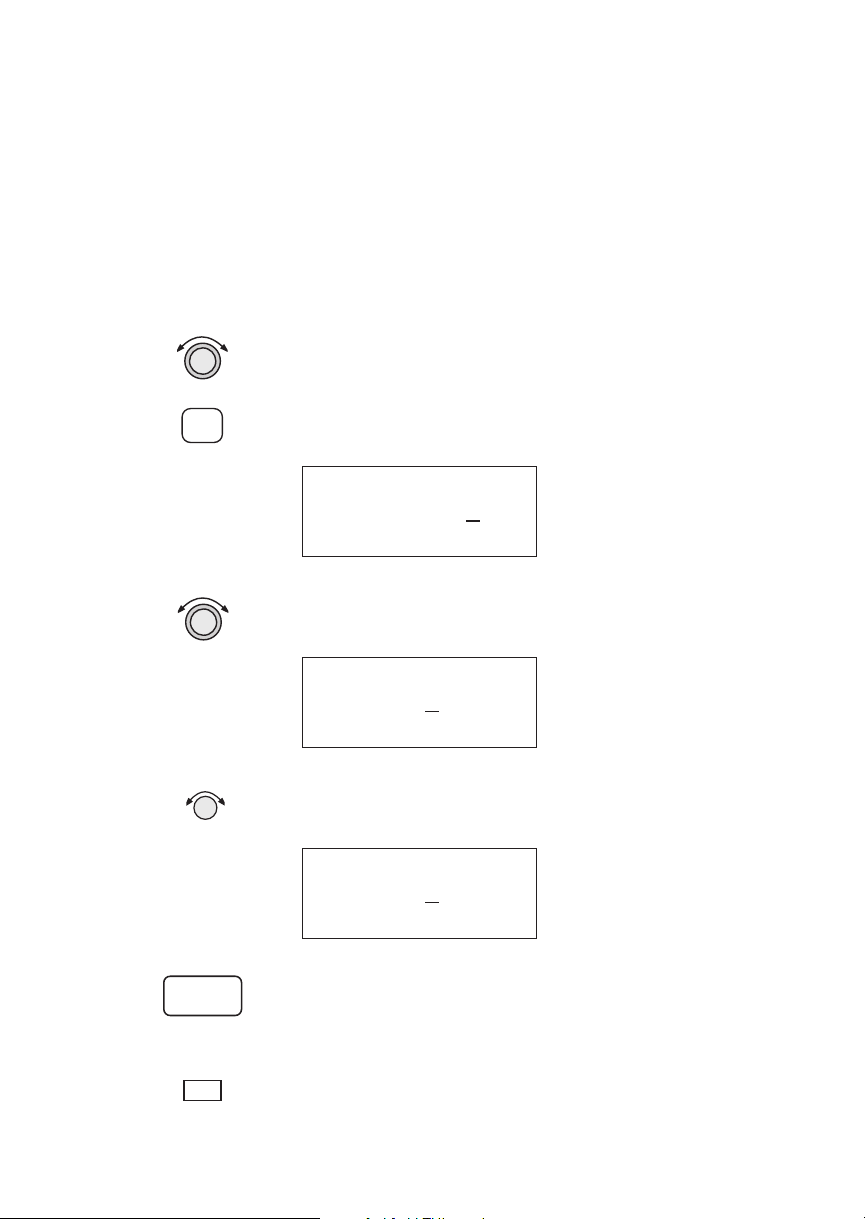
Navigation Basics
Countdown
Timer
SEL
The Countdown Timer allows you to set a timer that
will alert you when it expires with a flashing MSG
annunciator. The maximum time is 99:59:59 (hours,
minutes, seconds). The default time on power up is
the previous time that was entered. The factory
default time is 00:03:00 (3 minutes). You can stop the
timer by pressing
SEL twice while viewing the
Countdown Timer page.
1. While in the Navigation function, turn the
LARGE
knob to view the Countdown Timer page.
2. Press
SEL to start editing. The minutes value will
flash.
Countdown Timer
3. Turn the
00:03
LARGE knob to move between the time
:00
value fields.
Countdown Timer
00
:03:00
3-22
ENTER
MSG
4. Turn the
SMALL knob to edit the hours, minutes, or
seconds value.
Countdown Timer
01
:03:00
5. Press
ENTER to start the timer with the selected
time value. You can press
SEL to reset the timer
back to the selected time.
6. After the Countdown Timer value expires, press the
MSG key to note the time out message.
Page 61

Navigation Basics
Arc Assist The Arc Assist function will help you to navigate
along an arc. In the GX50/60, Arc Assist will help you
fly approaches with DME Arcs. Arc Assist can be used
as a user-defined arc to avoid special use airspaces, or
for conducting aerial searches using increasingly
larger circles. The Arc Assist page shows the direction
of the arc (left or right), the reference waypoint
identifier, the desired track for the arc, and the
distance to the reference waypoint.
ENTER
SEL
ENTER
Entry radial
005º
14 nm
Arc radius
The Arc Assist reference waypoint defaults to the
nearest VOR unless you have already selected one.
Press
waypoint. Press
ENTER to accept the displayed reference
SEL to choose another reference
waypoint.
1. In the Navigation function, turn the
reach the Arc Assist page. Press
LARGE knob to
ENTER to accept
the displayed reference waypoint and go to step 3 or
choose another waypoint and go to step 2.
Arc Assist
ref: UBG vor
Press ENT or SEL
3-23
Page 62

Navigation Basics
SEL
2. Press SEL. Choose another waypoint using the
LARGE and SMALL knobs.
VOR CVO
CORVALLIS
facil OR USA
ENTER
3. Select the Arc direction with the
SMALL knob.
Left Arc dtk 171
ref: CVO vor
Rad 005° 14.0nm·
Rght Arc dtk 351
ref: CVO vor
Rad 005° 14.0nm
4. Press
ENTER to accept the selections and start
navigating.
Note
The DTK on the Arc Assist page is the
no-wind heading to hold the distance
shown. It is a tangent to the current radial.
Other Uses for Arc Assist
You can select the reference waypoint for the Arc
Assist feature and it can be used at any time, not just
during approach or terminal operations. It can also
be used for difficult operations such as conducting an
over water search. By establishing a user waypoint at
the center of such a search area and selecting that
waypoint as a DME Arc reference point, you can fly
circles about that waypoint at known distances. By
gradually increasing the arc distance each time you
pass a specific radial, you can expand the search area.
The Arc Assist feature of the Apollo GX can make
this much easier.
3-24
Page 63

Navigation Basics
Waypoint
Distance Page
Waypoint ETE
Page
This page shows the cumulative distance from your
current position to each waypoint in the active flight
plan starting with the active leg. Turn the
SMALL
knob to view the next set of waypoints in your active
flight plan. The waypoint type is shown to the left of
the identifier. The allowable waypoint types are:
Airport (a), Intersection (i), NDB (n), and VOR (v).
The waypoint type symbol will not be shown if one of
the following occurs: the waypoint identifier is
unknown, it is an approach waypoint that is not one
of the four used types, it is a User waypoint, the
waypoint is not recognized by the current data card’s
database, or the data card has been removed.
aSLE ------nm
aPDX 43nm
aSEA 154nm
This page displays the cumulative time in hours and
minutes from your current position to each waypoint
in the active flight plan, starting with the active leg.
Turn the
SMALL knob to view the next page of
waypoints. The time will not be shown for the same
reasons as in the Waypoint Distance page.
From-To-Next
Waypoint ETA
Page
aSLE ete--:-aPDX ete00:25
aSEA ete01:32
This page displays the ETA for each waypoint in your
active flight plan from your current position, starting
with the active leg. Turn the
SMALL knob to view the
next page of waypoints. The time will not be shown
for the same reasons as in the Waypoint Distance
page, if the ground speed is zero, or if 3-D positioning
is lost.
aSLE eta--:-aPDX eta12:15
aSEA eta13:32
3-25
Page 64

Navigation Basics
From/To/Next
Waypoint
aSLE
The FROM/TO/NEXT Waypoint allows you to
view and/or edit a three waypoint mini-flight plan,
or view two legs of your flight plan, while within
the Nav function. These waypoints are like a three
waypoint window into your Active Flight Plan.
Changes to the FROM/TO/NEXT page change the
Active Flight Plan, and vice versa. You may also
Hold (sequencing suspended) or enable the TO
waypoint.
Note
Your flight plan will be placed on Hold
while you are editing the
FROM/TO/NEXT waypoints.
NEXT
WPT
TO
aPDX
Present
Po s i t i o n
WPT
vUBG
3-26
FROM
WPT
From SLE arpt
To UBG vor
Next HIO arpt
Creating FROM/TO/NEXT Waypoints
A - Set the FROM Waypoint
1. While in the Navigation function, turn the LARGE
knob to view the FROM/TO/NEXT page.
From ______
To ______
Next ______
Page 65

SEL
ENTER
Navigation Basics
2. Press SEL to start editing. Turn the LARGE knob to
select the FROM (first) waypoint position. Turn
the
SMALL knob, if necessary, so the flashing
selection shows “Ins?” (Insert). Press
ENTER.
From Ins?
To ______
Next ______
3. The Waypoint Type will flash. Choose the
Waypoint Type with the
SMALL knob.
AIRPORT AAF
APALACHIOCOLA
city FL USA
4. Turn the
LARGE knob to the first character of the
waypoint name. The first character of the waypoint
name will flash. Turn the
SMALL knob to select the
desired character.
AIRPORT EAA
EAGLE
city AK USA
5. Turn the
to the next character. Turn the
LARGE knob clockwise one click to move
SMALL knob to
select the desired character. Continue to select
additional characters.
AIRPORT EUF
EUFAULA
city AL USA
3-27
Page 66

Navigation Basics
6. Turn the LARGE knob clockwise one click to move
to the next character. Turn the
SMALL knob to
select the desired character. Continue to select the
needed characters.
AIRPORT EUG
EUGENE
city OR USA
ENTER
SEL
ENTER
ENTER
7. Press
ENTER when you have selected the desired
waypoint.
From EUG arpt
To ______
Next ______
B - Set the TO Waypoint
1. Press SEL and move to the TO waypoint with the
LARGE knob. The insert (Ins?) choice will flash.
Press
ENTER and then select the TO waypoint as
you did for the FROM waypoint.
From EUG arpt
To Ins?
Next ______
2. After selecting a TO waypoint, press
ENTER.
From EUG arpt
To SLE
Next ______
3-28
Page 67

C - Set the NEXT Waypoint
Navigation Basics
SEL
ENTER
ENTER
SEL
1. Press SEL and move to the NEXT waypoint with
the
LARGE knob. The insert (Ins?) choice will
flash. Press
ENTER and then select the NEXT
waypoint as you did for the FROM and TO
waypoints.
From EUG arpt
To SLE
Next Ins?
2. After selecting a NEXT waypoint, press ENTER.
From EUG arpt
To SLE arpt
Next HIO arpt
D - Editing FROM/TO/NEXT Waypoints
1. While in the Navigation function, turn the LARGE
knob to view the FROM/TO/NEXT page. Press
SEL to start editing.
From EUG arpt
To SLE arpt
Next Chg?
arpt
2. Turn the
LARGE knob to select the FROM, TO, or
NEXT waypoint field to edit.
From EUG arpt
To Chg?
arpt
Next HIO arpt
3-29
Page 68

Navigation Basics
ENTER
SEL
3. Turn the SMALL knob to choose the type of editing
you want to do. The flashing selection will ask you
to choose between Ins (Insert), Chg (Change), or
Del (Delete). The TO waypoint can also be placed
on Hold. Press
ENTER when you have selected the
editing option. When a waypoint is deleted, its
position will be replaced by dashes. The Chg and
Ins choices will allow you to select a new waypoint
as used in the previous examples.
Placing the TO Waypoint on Hold
1. Press
SEL and move to the TO designation with the
LARGE knob. You can also place the TO waypoint
on hold by pressing the external
GPS/SEQ) button, when it is installed. You can also
WPT SEQ (or
place a waypoint on Hold in the Flight Plan or
FROM/TO/NEXT functions. The HOLD
annunciator will light when it is installed to indicate
that automatic waypoint sequencing is suspended.
From EUG arpt
Hold?
SLE arpt
Next HIO arpt
3-30
ENTER
2. Turn the
SMALL knob to choose “Hold?” or “To?”
Placing the TO waypoint on Hold suspends
waypoint sequencing.
From EUG arpt
To?
SLE arpt
Next HIO arpt
3. Press
ENTER.
From EUG arpt
Hold SLE arpt
Next HIO arpt
Reverse the operation to return to normal sequencing.
Page 69

Navigation Basics
W
Using
Direct-To
Pressing the DIRECT-TO key sets your present
position as the FROM location. When using the
Direct-To function, the FROM waypoint identifier is
overwritten with the word “Direct.” If you remove the
Direct-To position with the Del? option, the old
FROM waypoint is returned to that position. If you
edit the FROM position, Direct-To navigation will be
replaced by the new entered waypoint.
TO
WPT
Present
Po s i t i o n
Direct-To
Route
FROM
PT
Direct-To
Waypoint
Direct-To Defaults
When you press
DIRECT-TO, the default waypoint
shown will be the current TO waypoint in the Nav or
Flight Plan functions or the waypoint displayed in the
Database or Info functions.
Function DIRECT-TO Waypoint Default
Nav
Database
Flight Plan
Info
Current TO waypoint
Displayed waypoint
Displayed leg TO waypoint
Displayed waypoint
You can always select a different Direct-To waypoint,
but the default is a useful starting point. While
viewing the default waypoint, press
then
ENTER to navigate directly to that waypoint.
DIRECT-TO and
3-31
Page 70

Navigation Basics
D
Direct-To Operation
1. Press the
DIRECT-TO key. The waypoint type will
flash.
AIRPORT HIO
PORTLAND
city OR USA
2. Select the new destination (TO) waypoint using
the
SMALL and LARGE knobs.
AIRPORT MMV
MC MINNVILLE
city OR USA
ENTER
Direct-To
Examples
3. Press
ENTER.
The following three examples provide some of the
more common ways that you can use the powerful
Direct-To function.
Center the CDI
After changing your course to avoid weather, an
obstacle, or being directed, you may need to reset your
course to center your CDI to continue navigating to
your intended TO waypoint.
MMV
Leg 2
SLE
Leg 1
Direct-To Course
Before After
3-32
EUG
Present
Position
CDI
CDI
Page 71

Navigation Basics
1. You flew to the right to avoid a storm cloud and
D
your CDI tells you to fly left, but you still have the
same TO waypoint. Press
DIRECT-TO. Your
current TO waypoint is displayed and the
Waypoint Type will flash.
AIRPORT SLE
SALEM
city OR USA
2. Press
ENTER
present position to your desired TO waypoint. Your
CDI will now be centered, as you are “on course.”
Enter a New Waypoint into a Flight Plan
While on a flight plan, you may want to temporarily
go to a new waypoint to look at something or you may
be directed by ATC. By using Direct-To, you can add
this new waypoint into your existing flight plan. This
way your flight plan is essentially unchanged, but you
were still able to react quickly to new conditions.
Make sure your Direct-To Entry Option is
set to “Never Clears,” or your active flight
plan will be deleted if the Direct-To
waypoint isn’t in your active flight plan.
See page 8 for details.
Before Adding Direct-To Waypoint
Leg 2
HIO
ENTER. You will now fly direct from your
Note
After Adding Direct-To Waypoint
Leg 3
DLS
Leg 2
HIO
DLS
MMV
Leg 1
SLE
MMV
(Direct-To
Waypoint)
Leg 1
SLE
3-33
Page 72

Navigation Basics
FPL
1. While on the first leg of your active flight plan, you
find out that you need to make another stop on the
way but you don’t want to change the rest of your
plan. Press
plan, turn the
FPL. While viewing the Active flight
SMALL knob to the first leg.
SLE to HIO
1** 345° 37.8nm
arpt arpt
D
ENTER
FPL
2. Press
DIRECT-TO. Select the desired waypoint
using the
LARGE and SMALL knobs.
AIRPORT MMV
MC MINNVILLE
city OR USA
3. Press
ENTER. The Nav function will now be
displayed with your new TO waypoint (MMV).
ete aMMV 00:20
0.011 “
Brg 321 15.6nm·
4. Check your active flight plan pages. Press
Turn the
SMALL knob, if necessary. Note that your
current leg now shows a direct flight to MMV.
direct to MMV
1** 321° 16.5nm
—— arpt
FPL.
3-34
5. Turn the
SMALL knob one click cw to check the
next leg. Note that your flight plan continues to
HIO as your original plan did. You have inserted a
new leg using the Direct-To function.
MMV to HIO
2* 003° 22.2nm
arpt arpt
Page 73

Navigation Basics
Direct-To OBS Pressing the DIRECT-TO key twice starts the OBS
desired track editor. OBS Desired Track allows entry
of a desired track to or from the current TO waypoint.
The current desired track in the navigation pages will
be replaced by the OBS Desired Track value entered.
You may also select the reference waypoint from your
active flight plan. Waypoint sequencing is normally
set as manual. When an approach is enabled, you may
select either manual or automatic. You may wish to
select manual sequencing so you may disable
sequencing if you will be in a holding pattern that
will cause you to continually cross the TO waypoint.
When your GX is configured to receive information
from the SL30 Nav/Comm, the OBS Desired Track
field is coupled to your HSI/CDI. Your HSI/CDI is
being read by the SL30 at the same time. Rotating the
control on your HSI/CDI will update the OBS
Desired Track on your Apollo GX. You can override
the HSI/CDI input to your Apollo GX by using the
concentric knobs of the GX as described below.
D D
1. Press
DIRECT-TO twice. The first character of the
Desired Track value will flash. Turn the
SMALL
knob to change the value.
OBS DTK: 100°
MMV arpt man
brg 000 dtk 000
2. Turn the
character. Turn the
LARGE knob to move to the next
SMALL knob to change the
value. You may also select the reference waypoint
from your flight plan waypoints.
OBS DTK: 115°
MMV arpt man
brg 000 dtk 000
3. When an approach is enabled, you may also select
between manual or automatic waypoint
sequencing. Setting sequencing to manual is useful
in the case where a holding pattern would allow
frequent sequencing and waypoint alerts.
3-35
Page 74

Navigation Basics
ENTER
4. Press ENTER when the choices are selected.
Turn
Anticipation
Aircraft
Present
Position
The Apollo GX will provide information for you to
smoothly transition from one flight plan leg to
another. Turns are drawn on the moving map. You
will receive a message about ten seconds before the
turn. The message will count down to the beginning
of the turn. The message shown below indicates that
you are arriving at the SLE waypoint, the next leg
desired track is 93°, and you should start your turn in
about nine seconds.
Arrival: SLE
Dtk 093°
Start Turn in 9
Standard Turn Operation
While you are in the turn, the desired track and cross
track are determined based on the turn. Turns are
made at three degrees per second if the ground speed
is under 250 knots. If ground speed is greater than 250
knots, the turn rate is set at 1.5 degrees per second.
SLE
30
Route
Line
MMV
44S
SLE
7S5
Turn Anticipation
Curves
6S4
010
24.2
Route
Line
If turn angle is greater than
120º, the turn will start well
before reaching the waypoint
3-36
Turn anticipation is not shown if the end of the turn
extends beyond the beginning of the next anticipated
turn. That is, if the two waypoints are too close, turn
anticipation will not be shown. Turn anticipation
curves are only drawn when the turn is greater than
5°. If the turn is greater than 120°, the Apollo GX will
generate a step turn message prior to the waypoint.
Page 75

Navigation Basics
Turn anticipation will not be available when
sequencing is on Hold; for the MAP or MAHP of an
approach; or for the “flyover” waypoints in an
approach.
Wind and Turn Anticipation
The graphic Turn Anticipation curve drawn on the
map display is based on your current ground speed.
Once you enter the turn, the graphic curve is no
longer updated. You may need to increase or decrease
your standard rate turn to compensate for wind. If
your installation includes a GPSS autopilot interface,
the Apollo GX will monitor your progress throughout
the turn and send corrections to the autopilot. Wind
conditions requiring steeper than maximum bank
angles may result in overshooting the new course line.
GPSS GPS Steering (GPSS) information is provided by
your Apollo GX when setup with a properly installed
autopilot. An autopilot guided by information from
your Apollo GX will be more accurate, faster
responding, and smoother than using a CDI. GPSS
works with the Flight Plan and Turn Anticipation
features to have your avionic equipment do more of
the work for you.
Standard GPSS Operation
Operating your Apollo GX with an autopilot is
simple:
1) Select a waypoint or flight plan in the Apollo GX.
2) Select GPSS mode on the autopilot or on the
HDG/GPSS selector switch (see your autopilot
operating instructions).
3) Fly. Your Apollo GX will direct the autopilot.
3-37
Page 76

Navigation Basics
Approach GPSS Operation
When the autopilot is directed by GPSS, there are few
considerations when flying an approach.
GPSS information will not be provided after you
·
pass the MAP. You need to follow the directions
published on the approach plate.
When directed to the MAHP, use the Direct-To
·
function. GPSS information will now once again
be provided to the autopilot.
Certain waypoints within an approach may be
·
coded as “Fly-over” waypoints. Fly-over
waypoints must be overflown before starting your
turn to the next waypoint. A turn anticipation
curve will not be drawn for these Fly-over
waypoints. The GPSS information from your
Apollo GX will handle this automatically.
GPSS Rules
There a few rules for providing valid GPSS
information to your autopilot. Your autopilot should
indicate when GPSS information is valid/invalid.
Refer to your autopilot operating instructions for
details.
3-38
Apollo GX Information
·
Your ground speed must be more than 5 kts
·
You are navigating to a waypoint (flight plan or
direct-to)
·
You are on the TO side of the waypoint
·
You are not executing Missed Approach
procedures
Autopilot Information
·
Horizontal bank output from the Apollo GX to
the autopilot is limited to 30° or less
·
Turn rate is 3°/sec at speeds less than 250 kts
Turn rate is 1.5°/sec at speeds greater than 250 kts
Page 77

Navigation Basics
Tuned Station When your Apollo GX is connected to and configured
to communicate with an Apollo SL30 Nav/Comm,
your Apollo GX will provide information about the
VOR or Localizer tuned by the SL30. The Apollo
SL30 with SW version 1.2, or later, sends the Tuned
Station information once every second. Earlier
versions of the SL30 only sends data when the
frequency is changed. If the Apollo GX shows a
different frequency than is shown on the SL30, press
the
F/F key on the SL30 to synchronize the units.
Reach the Tuned Station display, as shown below, by
pressing
NAV and turning the LARGE knob. The tuned
station identifier and its frequency are shown, as well
as the distance to it from your present position and
your current ground speed. The Distance, Speed, and
Time to waypoint information is sent by the Apollo
GX for display on your Apollo SL30. The pilot
should verify the station identification prior to
navigation use.
Nav Ident: vUBG
Freq: 117.40
13.5nm 200kts
Tuning to a VOR
The selected VOR frequency on the SL30 is sent to
your Apollo GX. The Apollo GX searches its database
for a unique identifier for that frequency within 200
nm of your position. If a unique match is found, the
selected VOR identifier, frequency, the distance from
your present position, and your ground speed are
shown on the Apollo GX display. The Apollo GX will
send Distance, Speed, and Time to waypoint
information to the SL30. If no frequency is found, or
two or more are found, within 200 nm, no
information will be displayed. All VORs are utilized,
even those without TACAN or DME. Once a VOR is
identified it will continue to be tracked even beyond
200 nm.
3-39
Page 78

Navigation Basics
Tuning to a Localizer
When the connected SL30 is tuned to a Localizer
frequency, the SL30 sends the decoded Localizer
identifier to the Apollo GX. The Apollo GX searches
its LOC-DME database for an identifier match. If the
Localizer is found to be a co-located LOC-DME, the
Apollo GX will provide Distance, Speed, and Time
information to the SL30 and for the Tuned Station
page on the GX.
3-40
Page 79

Moving Map Functions
)
Moving Map Functions
Press the MAP key to reach the Moving Map function
and view the progress of your flight on a graphic
display. Your present position, nearby waypoints, and
special use airspaces display options are
user-selectable. Three main pages are available in the
Moving Map function: full screen map, split screen
with map and Nav info, Search & Rescue (SAR) when
selected, and map setups.
Turn LARGE Knob
Map+Nav
(+ Comm GX60/65)
Full Screen
Map
Map +
Nav Info
Map
Only
* When enabled
SAR Map*
Press Smart Key
Grid
Marker
Pattern
Map
Setup
Route Line, Map Orient,
& Map Reference
Symbol & ID Setup
Track History (On, Save By, Interval)
Track History (Strategy, Clear, % Used
Airspace Setup
Turn SMALL Knob
Airspace Buffers
ATC Ring
Airspace Types
(B, C, MOA, Training, Unknown,
Alert, Caution, Danger, Restricted,
Prohibited, & Warning)
SAR Setup*
SAR Position*
The full screen map page of the Moving Map
function shows a graphic map of the aircraft position,
nearby user-selected waypoints, airspaces, track
history, and your route. The aircraft position is shown
by an airplane symbol near the center of the display.
The TO waypoint identifier is shown in reversed text
on the upper left corner. The bearing from your
current position to the TO waypoint is shown on the
upper right corner. The map scale is shown in the
lower left corner. The distance from the current
position to the TO waypoint is shown in the lower
right corner.A5nm“ATC Ring” can be drawn
around airports that have a control tower.
4-1
Page 80

Moving Map Functions
TO Waypoint
Identifier
Route Line
Waypoint
Location
Symbol
Map Scale
Controls
Special Use
Airspace
Sector
Waypoint
Identifier
Present
Position
Symbol
Special Use
Airspace
Outer Ring
Bearing to
the TO
Waypoint
ATC Ring
- approx.
5 nm Radius
Distance to
the TO
Waypoint
The LARGE knob moves to different pages of the Map
function and selects waypoints when scanning. The
SMALL knob changes the map scale.
Waypoint Type Keys
The smart keys select the display of the waypoint
types. The waypoint types selectable from the map
view are: Airports, VORs, Intersections, User-defined,
and NDBs. Press the smart key to control the display
of the waypoint type. There are three selections
possible: waypoint identifier and location symbol,
location symbol only, and off. Pressing the smart key
subsequent times will control which selection is
made. The change will also be displayed on the map
setup pages.
4-2
APT
APT
APT
2
A solid, reversed waypoint type annunciator above the
smart key means the waypoint identifier and location
symbol will both be displayed. A bold outline of the
waypoint type annunciator will show only a symbol
on the waypoint location. A thin outline around the
waypoint type means that it is turned off and no
information for that waypoint type will be displayed
on the map.
Waypoint List Keys
The Waypoint List smart key shows a number. Press
the key to scroll through the list of available waypoint
types available for selection.
Page 81

Moving Map Functions
Waypoint Scan Key
The Waypoint Scan smart key allows you to select an
airport to get information about while viewing the
map.
SCAN
INFO
SCAN
MAP
1. Press the
2. Turn the
SCAN smart key.
LARGE knob to highlight the desired
waypoint identifier.
3. Press
INFO to get information about the waypoint.
Press
INFO to return to the map display. You may
also press
DIRECT-TO and then ENTER to go
direct-to the highlighted airport.
4. Press the
SCAN key again to return the LARGE knob
to normal operation.
Map Scale
The Map Scaling is controlled by turning the
SMALL
knob while viewing the map. The map scale value
shown is the vertical height of the screen in nautical
miles. Map scale choices in nautical miles are: 0.1, 0.2,
0.5, 1, 2, 5, 10, 15, 20, 30, 40, 50, 75, 100, 150, 200, 250,
and auto. The auto selection automatically adjusts the
map scale so the “TO” remains on the display until
the aircraft passes over the waypoint.
1. Press
2. Turn the
MAP.
SMALL knob to adjust the map scale.
Map and Nav
Info
3. Turn the
LARGE knob to view the other Map
function displays.
The Map and Nav Info page of the Map function
provides a split screen showing the moving map and
selected navigation information. The navigation
information provided on the right side of the display
includes: the current TO waypoint identifier, distance
and bearing to the TO waypoint from your current
position, ground speed, aircraft current track, and the
map scale.
4-3
Page 82

Moving Map Functions
ance&
Route Line
Your Present
Position
Cross Track Error
Dist
Direction
Map Setup
TO Waypoint
Identifier
Special Use
Airspace
Distance to
the TO
Waypoint
TOWaypoint
Identifier
t
o
aPDX
44.2
123
nm kt
½
005
006
brg trk
0.01> 30
Ground
Speed
Bearing to
the TO
Waypoint
Current
Track
Map Scale
The map setup function allows you to select the route
line, map orientation, waypoint types that will be
displayed, airspace type, and special use airspaces, as
well as what airspace alerts will appear when an
airspace is penetrated.
Route Line
A Route Line can be drawn for the legs of the active
route when the selection is turned on. A route line is
not drawn for procedure turns.
Route
Line
093
Bearing to
the TO
Waypoint
a6S4
ATC
Ring
MMV
44S
Route
Line
Map Scale
SEL
RTE
4-4
SLE
7S5
30
1. In the Map function, turn the
the Map Setup page. Press
6S4
24.2
LARGE knob to reach
SEL to start selection of
the Route Line. The Route Line selection will
flash. Or, press the RTE smart key to toggle
through the choices.
Route Line:On
Map Orient:North
Map Ref:Plane ·
Distance to
the TO
Waypoint
Page 83

Moving Map Functions
2. Turn the SMALL knob to choose On or Off.
ENTER
SEL
3. Press
ENTER when you made your selection, or
turn the
LARGE knob to the next item.
Map Orient
The Map Orient selection allows you to choose how
the top of the map display is oriented.
North Up - The display is oriented so that vertical
lines on the map are aligned with magnetic north.
The aircraft symbol is centered in the display and
will point towards the direction you are flying.
DTK Up - The Desired Track for the current flight
plan leg is the top of the display. The aircraft
symbol is at the bottom of the display and will
point towards the direction you are flying.
Track Up - The direction that your aircraft is moving
towards is at the top of the display. The aircraft
symbol is at the bottom of the display.
1. In the Map function, turn the
the Map Setup page. Press
LARGE knob to reach
SEL. Turn the LARGE
knob to choose Map Orient for selection. Or, press
the Map Orient (ORI) key to toggle through the
choices.
ORI
ENTER
Route Line:On
Map Orient:North
Map Ref:Plane ·
2. Turn the
SMALL knob to choose North, DTK, or
Track.
3. Press
ENTER when you made your selection, or
turn the
LARGE knob to the next item.
4-5
Page 84

Moving Map Functions
Map Reference
The Map Reference selection allows you to choose
either the Destination Waypoint (Dest) or your
current position with an airplane icon (Plane) as the
center point of the Moving Map display.
SEL
REF
ENTER
1. In the Map function, turn the
the Map Setup page. Press
flash. Turn the
LARGE knob to choose Map Ref for
LARGE knob to reach
SEL. The value will
selection. Or, press the Map Reference (REF) smart
key to toggle through the choices.
Route Line:On
Map Orient:North
Map Ref:Plane
2. Turn the
Press
SMALL knob to choose Dest or Plane.
ENTER after completing your choices. It is not
necessary to press
ENTER if you used the smart key.
·
Identifier and Waypoint Type Selection
The Identifier & Waypoint Type page allows you to
choose the type of waypoint identifiers that will be
displayed on the moving map. You may control the
look of your map screen for each type of waypoint by
choosing to show the symbol and Identifier, symbol
only, or to turn that type of waypoint “Off.” The
symbol for each waypoint type is shown in each
selection. When “Off” is selected, no symbol or
identifier will be displayed for that waypoint type.
You may use the “smart” keys to toggle through the
selections. The “smart” keys always allow you to
select their waypoint type while viewing the MAP
display. Note that an airport with a runway of 0
length will not appear on either the nearest list, or on
the map if a length is set for the runway limit. See
page 12 for details on Runway Limits.
4-6
Page 85

Moving Map Functions
Note
Waypoints that are in an active flight plan
will show up on the moving map even if its
waypoint type is set as “Off.”
SEL
1. In the Map function, turn the
the Map Setup page. Turn the
Identifier & Waypoint Type page. Press
LARGE knob to reach
SMALL knob to the
SEL to start
editing the waypoint types.
APT:¿ID INT:+ID
VOR:ÂID NDB:ÁID
Usr:ÀID
2. Turn the
that you want to edit. Turn the
LARGE knob to choose the waypoint type
SMALL knob to
choose symbol and identifier (ID), symbol only, or
“Off.” In this example, the flashing (underlined)
selection would show both the symbol and
identifier for intersections.
APT:¿ID INT:+ID
VOR:ÂID NDB:ÁID
Usr:ÀID
3. Turn the
SMALL knob to select the combination
you want shown on the Map display. In this
example, only the symbol (+) will be shown on the
Map display for Intersections.
ENTER
APT:¿ID INT:+
VOR:ÂID NDB:ÁID
Usr:ÀID
4. Press
ENTER when you have completed your
selections, or turn the
LARGE knob to the next item.
4-7
Page 86

Moving Map Functions
Track History
Your Apollo GX can store a record of its progress in
memory that will be shown on the display. The Track
History is shown as a series of points on the display
following the path of the plane icon. Track history
may be recorded by time or by distance at a selected
interval. You may also select the Strategy for storing
the track history points. The Full strategy choice
means that track points will be stored until memory is
full. Subsequent track points will not be stored. The
Forever strategy will overwrite previous track points
when memory is full. The Clear Track selection
allows you to clear the existing track history memory
whenever you select Yes. The %used value shows the
percentage of track history used.
Track History Recording Points
4-8
SEL
Track History function has two pages where you may
set the following options:
·
Track History On/Off
·
Save by Distance/Time
·
Interval for saving Track History
·
Strategy (Full/Forever)
·
Percentage of memory used (status only)
1. In the Map function, turn the
the Map Setup page. Turn the
first Track History page. Press
the waypoint types. Pressing the
keys toggle the available options. Pressing the
LARGE knob to reach
SMALL knob to the
SEL to start editing
TRK and SAV smart
INTV
smart key enables selection of the interval value.
Page 87

Trk History:Off
Save By:Distance
Interval:0.5
Moving Map Functions
ENTER
SEL
2. Turn the
3. Turn the
the
4. Turn the
the
SMALL knob to select On or Off.
LARGE knob to the Save By option. Turn
SMALL knob to choose Distance or Time.
LARGE knob to the Interval option. Turn
SMALL knob to choose the Interval value. If you
chose to Save By Distance, select a distance
between 0.1 and 10.0 nm. If you chose Save By
Time, select a time between 1 sec. (00:01) and 10
minutes (10:00).
5. Press
ENTER when you have completed your
selections.
6. Turn the
Track History page. Press
SMALL knob clockwise to the second
SEL to start selection or
press the appropriate smart key. The Strategy value
will flash. Turn the
SMALL knob to change the
value.
Strategy:Full
Clear Track:No
%used:12
ENTER
7. Turn the
Turn the
LARGE knob to the Clear Track option.
SMALL knob to choose Yes to clear
(delete) existing Track History or No to leave
existing Track History in place. If you select Yes for
Clear Track, the %used value will return to zero.
8. Press
ENTER when you have completed your
selections.
4-9
Page 88

Moving Map Functions
Airspace Setup
The Airspace Setup selections allows you to turn
Airspace notification (Alerts) or map display of
Airspaces On or Off, select the distance and time
buffers for airspace alerts, turn ATC rings On or Off,
and to choose the Airspace types that will be used.
Airspace alerts will not be given during an approach.
SEL
ENTER
1. In the Map function, turn the
LARGE knob to reach
the Route Line/Map Orient page. Then, turn the
SMALL knob two clicks clockwise. The Airspace
Setup page is shown.
Airspace Setup
Map : ON
Alerts: ON
2. Turn the
SMALL knob to view the pages for Airspace
Setup. On this page you may select whether Airspaces
are shown on the Map display or whether Airspace
Alerts are provided. Press
Map choice will flash. Turn the
SEL to start selection. The
SMALL knob to select
On or Off. The Map (MAP) and Alert (ALE) “smart”
keys also select the options.
Airspace Setup
Map : Off
Alerts: Off
3. Turn the
LARGE knob to move to the Alerts choice.
This sets the Alert value for all airspaces. If set to ON,
each airspace alert may be set separately. Setting Alerts
OFF turns off all airspace alerts. Turn the
SMALL
knob to select On or Off. Press ENTER after
completing your choices. Airspace alerts are
automatically disabled when an approach is enabled.
4-10
Airspace Setup
Map : On
Alerts: On
Page 89

Moving Map Functions
Airspace Buffers
Three values may be adjusted for Airspace Buffers for
determining CLOSE information: distance, elevation,
and time. CLOSE distance may be from 0 to 99 nm at
one nm intervals. Altitude values are from 0 to 9900 feet
in 100 foot intervals. Time values are from 0 to 20
minutes in one minute intervals. From the Map Setup
page, turn the
SMALL knob three clicks cw to reach
the Airspace Buffers page.
SEL
ENTER
1. While viewing the Airspace Buffer page, press
The distance value will flash.
Airspace Buffers
Dist Alt Time
2
nm 500’ 10min
2. Turn the
change. Turn the
LARGE knob to select the desired value to
SMALL knob to change the value.
Airspace Buffers
Dist Alt Time
2nm 5
3. Press
00’ 10min
ENTER when the desired values have been
selected.
Airspace Buffers
Dist Alt Time
2nm 200’ 10min
SEL.
4-11
Page 90

Moving Map Functions
ATC Ring Selection
When this choice is turned ON,a5nmradius
artificial “ATC Ring” is drawn on the Map display
around airports that have a control tower. From the
Map Setup page, turn the
to reach the ATC Ring selection page.
1. While viewing the ATC Ring page, press SEL to
SEL
start selection.
2. Turn the SMALL knob to choose ON or OFF. Press
ENTER after completing your selection.
ENTER
Airspace Selections
The Airspaces available for selection are: Class B (Off,
Outer, or Sector), Class C (Off, Outer, or Sector),
MOA, Training, Unknown, Alert, Caution, Danger,
Restricted, Prohibited, and Warning. You may select
ON or OFF for map display and alerts for each
Airspace type.
SMALL knob four clicks cw
5 nm ATC Rings
Map : Off
5 nm ATC Rings
Map : On
Outer Sector
4-12
Page 91

Moving Map Functions
The Outer selection refers to the outline of the outside
ring extended from the ground on up. Selecting Outer
will be useful to VFR pilots who wish to avoid all
airspaces. The sector selection refers to the outside
edges of the sector from the ground on up unless you
have altitude input which then allows for
3-dimensional information. The Sector selection is
the default setting and is most useful for IFR flight.
An airspace will appear in the Nearest list even if the
map or alert selections are set to off. The Map (MAP)
and Alert (ALE) “smart” keys also select the options.
SEL
1. While viewing the Map Setup page, turn the
knob to the Airspace Setup page. Turn the SMALL
knob to view the desired Airspace selection page.
Class B Airspace
Map : Off
Alert : Off
2. Press
SEL to activate selection. Turn the SMALL
knob to change the selection.
Class B Airspace
Map : Sector
Alert : Off
3. Turn the
Turn the
LARGE knob to move to the next selection.
SMALL knob to select your choice.
Class B Airspace
Map : Sector
Alert : Outer
SMALL
ENTER
4. Press ENTER after making the selection. Turn the
SMALL knob to view the other Airspace pages.
4-13
Page 92
Moving Map Functions
Search and
Rescue
GRD
MRK
PAT
TO Waypoint
Identifier
Grid
Number
Map Scale
When activated, the Search and Rescue (SAR) feature
allows a simplified, automated method of performing
search patterns. The search patterns supported
include parallel line, creeping line, and expanding
square. A line showing the route of the pattern may
also be displayed on the screen of your GX. Patterns
can be based on two grid types: aeronautical sectional
charts (US) and a Lat/Lon grid system (Basic). The
grid system can be displayed on the Moving Map, as
well as the search pattern.
Search and Rescue Map Description
The Search and Rescue map page is essentially the
same as the regular full map with the addition of the
SAR features. However, at various zoom levels,
underlying waypoint information will not be shown
to allow for the display of SAR information. Smart
keys control the Grid Lines (GRD), mark a position
with a new User waypoint (MRK), and select a search
pattern (PAT).
aTTD
ab
391
c
ab
423
c
20
Plane Reference Icon
d
d
ab
392
c
ab
424
c
d
d
ab
c
ab
c
GRD4MSG PATMRK
393
425
d
d
T
010
T
ab
394
d
c
ab
426
d
c
27.3
Bearing to
the TO
Waypoint
Quarter Grid
Letter
Distance to
the TO
Waypoint
4-14
Page 93

Moving Map Functions
Grid Line Display
While viewing the Search and Rescue (SAR) map
page, you can choose how the grid lines are displayed.
Press the
GRD smart key to change the Grid line view.
Grid line selection options are slightly different for the
two grid types, US and Basic. As you zoom out to
approximately 40nm the grid lines will be removed.
US Grid Type
The US Grid selection is based on sectional charts as
shown in the Sectional chart table.
GRD - No grid lines
GRD 1 - Section lines
GRD 2 - Section lines and section number
GRD 3 - Section lines, section number,
and quarter section lines
GRD 4 - Section lines, section number, quarter
section lines, and quarter section letters
T
aTTD
010
T
GRID1
GRID2
GRID3
GRID4
20
aTTD
20
aTTD
20
aTTD
ab
391
c
ab
423
c
20
d
d
SAR000
SAR003
SAR002
392391
SAR000
SAR003
SAR002
392391
SAR000
SAR003
SAR002
ab
392
d
c
SAR000
ab
SAR003
424
d
c
SAR002
425424
425424
ab
393
d
c
ab
425
d
c
27.3
T
010
T
394393
426423
27.3
T
010
T
394393
426423
27.3
T
010
T
ab
394
d
c
ab
426
d
c
27.3
Map Display
Grid Lines
No Grid Number
Map Display
Grid Lines
Grid Numbers
Map Display
Grid Lines
Grid Numbers
Quarter Grid Lines
Map Display
Grid Lines
Grid Numbers
Quarter Grid Lines
Quarter Grid Letters
4-15
Page 94

Moving Map Functions
º
º
Basic Grid Type
GRD – No grid lines
GRD1–60minute grid lines
GRD2–30minute grid lines
GRD3–15minute grid lines
Search and Rescue Map Setup Page
The SAR Map Setup page provides selection of SAR
Map (Off/On), Grid Type (US/Basic), and the
Position (area of operation).
46º
45º
30’
15’
124
ab
a b
d
c
ab
c d
d
c
30’ 15’
123
ab
d
c
ab
d
c
4-16
SEL
1. From the Map Setup Page, turn the
SMALL knob
counterclockwise two clicks to the SAR Map Setup
page.
Sar Map :Off
Grid Type:US
Position :SEA
2. Press
SEL to allow selection of the Search and
Rescue feature. Turn the
SMALL knob to set the
SAR Map value to ON or OFF. When SAR Map is
set to ON, the SAR Map will be available. When
set to OFF, the SAR Map will not be shown. The
SAR smart key toggles SAR Map On or Off.
3. Turn the
LARGE knob to Grid Type. Turn the
SMALL knob to choose US or Basic. The US Grid
Type Position is based on sectional aeronautical
chart grids. The Basic Grid Position is based on
Lat/Lon positions. The
GRD smart key toggles
between US or Basic.
Page 95

Moving Map Functions
4. Turn the LARGE knob to Position. Turn the SMALL
knob to choose the position information. If you
selected the US Grid type, choose the desired
sectional name with the
SMALL knob or the POS
smart key. See the following Sectional Aeronautical
Chart Grids table for the location nearest you
operation.
For the Basic Grid type, select the Position
quadrant (NW, SW, NE, or SE) with the
SMALL
knob or the POS smart key. Quadrant lines are
defined by the Equator, Prime Meridian, and the
International Date Line. For example, the
continental U.S. Would be in the NW quadrant,
Denmark would be in the NE quadrant, Buenos
Aires, Argentina is in the SW quadrant, and
Riyadh, Saudi Arabia is in the SE quadrant.
ENTER
Sar Map :On
Grid Type:Basic
Position :NW
3. Press
4. Now, turn the
ENTER.
LARGE knob ccw to the SAR Map
page.
4-17
Page 96

Moving Map Functions
)
Set the SAR Position (Basic Grid Type)
1. If you selected the Basic Grid Type, you need to set
the SAR Position. From the SAR Map Setup page
turn the
Position page. The SAR Position page only appears
when the Basic Grid Type is selected. The Position
location refers to the LAT/LON of the southeast
starting corner for the selected grid.
50º
40º
SMALL knob clockwise to the SAR
120º130º
One degree grid square
SAR Position
Reference Point
(i.e. Lat 40 and Lon 120
4-18
SEL
ENTER
SAR Position
Latitude :40
Longitude:120
2. Press
SEL and use the SMALL and LARGE knobs to
set the grid position. The
LAT and LON smart keys
activate selection of the Lat and Lon coordinates.
Coordinates are selected in 10º increments.
3. Press
ENTER.
Page 97

Moving Map Functions
Sectional Aeronautical Chart Grids
Chart Ident North
Seattle SEA 49°00N 44°30N 125°00W 117°00W 576 32
Great Falls GTF 49°00N 44°30N 117°00W 109°00W 576 32
Billings BIL 49°00N 44°30N 109°00W 101°00W 576 32
Twin Cities MSP 49°00N 44°30N 101°00W 93°00W 576 32
Green Bay GRB 48°15N 44°00N 93°00W 85°00W 544 32
Lake Huron LHN 48°00N 44°00N 85°00W 77°00W 512 32
Montreal MON 48°00N 44°00N 77°00W 69°00W 512 32
Halifax HFX 48°00N 44°00N 69°00W 61°00W 512 32
Klamath Falls LMT 44°30N 40°00N 125°00W 117°00W 576 32
Salt Lake City SLC 44°30N 40°00N 117°00W 109°00W 576 32
Cheyenne CYS 44°30N 40°00N 109°00W 101°00W 576 32
Omaha OMA 44°30N 40°00N 101°00W 93°00W 576 32
Chicago ORD 44°00N 40°00N 93°00W 85°00W 512 32
Detroit DET 44°00N 40°00N 85°00W 77°00W 512 32
New York NYC 44°00N 40°00N 77°00W 69°00W 512 32
San Francisco SFO 40°00N 36°00N 125°00W 118°00W 448 28
Las Vegas LAS 40°00N 35°45N 118°00W 111°00W 476 28
Denver DEN 40°00N 35°45N 111°00W 104°00W 476 28
Wichita ICT 40°00N 36°00N 104°00W 97°00W 448 28
Kansas City MKC 40°00N 36°00N 97°00W 90°00W 448 28
St. Louis STL 40°00N 36°00N 91°00W 84°00W 448 28
Cincinnati LUK 40°00N 36°00N 85°00W 78°00W 448 28
Washington DCA 40°00N 36°00N 79°00W 72°00W 448 28
Los Angeles LAX 36°00N 32°00N 121°30W 115°00W 416 26
Phoenix PHX 35°45N 31°15N 116°00W 109°00W 504 28
Albuquerque ABQ 36°00N 32°00N 109°00W 102°00W 448 28
Dallas-
Ft. Worth
Memphis MEM 36°00N 32°00N 95°00W 88°00W 448 28
Atlanta ATL 36°00N 32°00N 88°00W 81°00W 448 28
Charlotte CLT 36°00N 32°00N 81°00W 75°00W 384 24
El Paso ELP 36°00N 28°00N 109°00W 103°00W 384 24
San Antonio SAT 32°00N 28°00N 103°00W 97°00W 384 24
Houston HOU 32°00N 28°00N 97°00W 91°00W 384 24
New Orleans MSY 32°00N 28°00N 91°00W 85°00W 384 24
Jacksonville JAX 32°00N 28°00N 85°00W 79°00W 384 24
Brownsville BRO 28°00N 24°00N 103°00W 97°00W 384 24
Miami MIA 28°00N 24°00N 83°00W 77°00W 384 24
Grid Limit
GSW 36°00N 32°00N 102°00W 95°00W 448 28
South
Grid Limit
West Grid
Limit
East Grid
Limit
Total
Grids
Grids/
Row
4-19
Page 98

Moving Map Functions
Selecting A Pattern
Three pattern types provide you with the ability to
perform a search that best suits your needs. The three
types include Parallel Line, Creeping Line, and
Expanding Square.
PAT
ENTER
ENTER
ENTER
PAT
1. While viewing the SAR Map page, press the
(Pattern) smart key.
2. Turn the
type. Press
SMALL knob to select the desired pattern
ENTER to choose the pattern and to start
selecting the available options.
Parallel Line
Search Page
Press ENTER
3. Select the desired options and press
4. Press
ENTER to activate the search pattern. You will
ENTER.
automatically return to the SAR Map page. The
PAT annunciator above the smart key will be
highlighted.
5. Press
PAT again to disable the search pattern. The
PAT annunciator above the smart key will no
longer be highlighted.
PAT
4-20
Page 99

Moving Map Functions
3
Parallel Line Search Pattern
The Parallel Line search pattern selection allows you
to create a search pattern along parallel lines based on
an established grid.
Start
Point
34 7 8 1112
PAT
ENTER
SEL
12569 101
·
Select grid
·
Set spacing
·
Set direction
·
Activate pattern
1. While viewing the SAR Map page, press the
smart key.
2. Turn the
pattern type, if necessary. Press
3. Press
SMALL knob to select the Parallel Line
ENTER.
SEL to start editing the Grid selection. The
first character will flash.
Grid (US):453C1
Spacing :0.5
Direction :N / S
PAT
4-21
Page 100

Moving Map Functions
4. Use the LARGE and SMALL knobs to select the
desired Grid.
ENTER
ENTER
ENTER
PAT
5. Turn the
the
LARGE knob to the Spacing option. Turn
SMALL knob to select the desired pattern
spacing. You may select between 0.2 and 9.9 nm.
6. Turn the
option. Turn the
LARGE knob to the Direction of Travel
SMALL knob to select the desired
Direction of Travel. You may select N/S or E/W.
7. Press
8. Press
ENTER when selections are complete.
ENTER to activate the search pattern. You will
automatically return to the SAR Map page. The
PAT annunciator above the smart key will be
highlighted.
9. Pressing the
PAT smart key again will disable the
pattern.
4-22
 Loading...