

Page 1
APOLLO Gate Operators, Inc.
Model 3500 Commercial Swing Gate Operator
Now with new current sense adjustment procedure - see page 14
INSTALLATION MANUAL
052004
Page 2

CONTENTS
IMPORTANT SAFETY INSTRUCTIONS……………. 3
Applications .............................................................. 4
Pre-Installation Checklist ........................................ 5
Parts Identification ................................................... 6
Post Location Guide ………………………………….. 7
Operator Installation ................................................ 8-13
EMERGENCY MANUAL OPERATION ……………… 13
Programming Current Sensing ……………………… 14
835/836 Control Board Description …………………. 15-19
Siren Installation ……………………………………….. 20
Radio Receiver Options ............................................. 21
Troubleshooting guide .............................................. 22-24
Warranty .................................................................... 25
Page 3

IMPORTANT SAFETY INSTRUCTIONS
WARNING - To reduce the risk of injury or death:
• READ AND FOLLOW ALL INSTRUCTIONS.
• Installation should be performed by a professional installer.
• Required welding should be performed by a qualified welder.
• Should electricity be required, use a certified electrician only.
• Any device that requires 120 Volts AC should be U.L. approved.
• Review with the owner all safety concerns including:
⇒ Do not operate the gate unless area around gate is in full view.
⇒ Never let children operate or play with gate controls. Keep the remote control
away from children.
⇒ Always keep people and objects away from the gate. NO ONE SHOULD CROSS
THE PATHE OF THE MOVING GATE.
⇒ Periodically test the obstruction sensitivity to assure safe and proper
operation. Do not test sensitivity by standing between the gate and the hinge or
stop post.
⇒ Do not allow children to play with the gate controls.
⇒ The “CAUTION AUTOMATIC GATE” signs should be clearly visible from both
sides of the gate.
⇒ Always insure that the gate has closed securely before leaving area.
⇒ Arrange with local fire and law enforcement for emergency access.
• Use the emergency release only when the gate is not moving.
• Recommend safety devices such as loop detectors, edge switches, and beam
detectors when applicable.
• Install control devices such as keypads far enough away (5 feet or further) from any
moving parts of the operator and gate to prevent possible injury.
• Do not install control box where the gate can come in contact with person using the
push button on side of control box.
• Always disconnect the battery or power source when making adjustments or repairs to
any part of the gate or operator.
• All rollers should be covered to prevent injury.
• KEEP GATES PROPERLY MAINTAINED. Read the owner’s manual. Have a qualified
service person make repairs to gate hardware.
• The entrance is for vehicles only. Pedestrians must use separate entrance.
Test the gate operator monthly. The gate MUST reverse on contact with a rigid object or
stop when an object activates the non contact sensors. After adjusting the force or limit of
travel, retest the gate operator. Failure to adjust and retest the gate operator properly can
increase the risk of injury or death.
SAVE THESE INSTRUCTIONS.
Page 4

APPLICATIONS
The Model 3500 Swing Gate Operator is approved for Vehicular Class I & II usage
under UL 325 Guidelines, and is designed to handle swing gates up to 20 feet in
length and 800 pounds each. A professional fence or gate dealer is recommended
to assure proper installation. The Model 3500 operator is 12 Volt DC (Direct
Current) powered. There are several advantages with 12 Volt DC systems:
• Low voltage virtually eliminates risk of electrical shock.
• Battery powered operators provide up to 200 operations in the event of
power outages.
• The battery may be recharged with a battery charger or by solar energy
(eliminating the need for costly trenching to remote entrances).
If a battery charger is used and a standard electrical outlet is not readily available, a
licensed electrician will be required for proper electrical hook up.
The following table should be used as a guide for capacity of operation of operators
only, additional options may reduce the the daily usage. Please note that the charge
capability of solar panels will vary with different geographical locations.
Charging Methods for Average Daily Usage
Model # Daily Usage ---> 1-10 1-20 1-40 1-60 1-80 80+
201 5 watt solar panel
210 10 watt solar panel
MSX20 20 watt solar panel (requires 5310 regulator)
MSX30 30 watt solar panel (requires 5310 regulator)
MSX40 40 watt solar panel (requires 5310 regulator)
404 1.5 amp battery charger
405 10 amp battery charger
Note: Double the amount of solar panels for dual gate operators.
*
*
*
*
*
*
*
Page 5

PRE-INSTALLATION CHECKLIST
The following check list should be used before beginning installation:
Verify that the proper operator has been selected for this application.
Verify proper installation and operation of the gate.
1. Are the hinges servicable?
2. Does the gate swing free and level?
3. Will the gate require a locking device?
4. Is the hinge and stop posts sturdy enough to handle the gate & operator?
5. Does the gate meet U.L. construction?
Determine the general location of the operator, attachment points, and solar
panel (if used).
1. Is there a suitable location for the operator?
2.Can the solar panel (if used) be mounted in an unobstructed area facing
south (in the northern hemisphere)?
3. Will additional solar panel cable be required?
4. Is electricity available (if required)?
Consider safety and access options. Recommend if needed.
1. Will there be children or animals in the area?
2. Are safety loops, edge switches, or photo beam detectors required?
3. How can the gate be opened in emergencies?
4. How will visitors enter and exit?
5. Will vehicles (and trailers) have sufficient room off roadway to operate any
control devices such as keypads?
Page 6
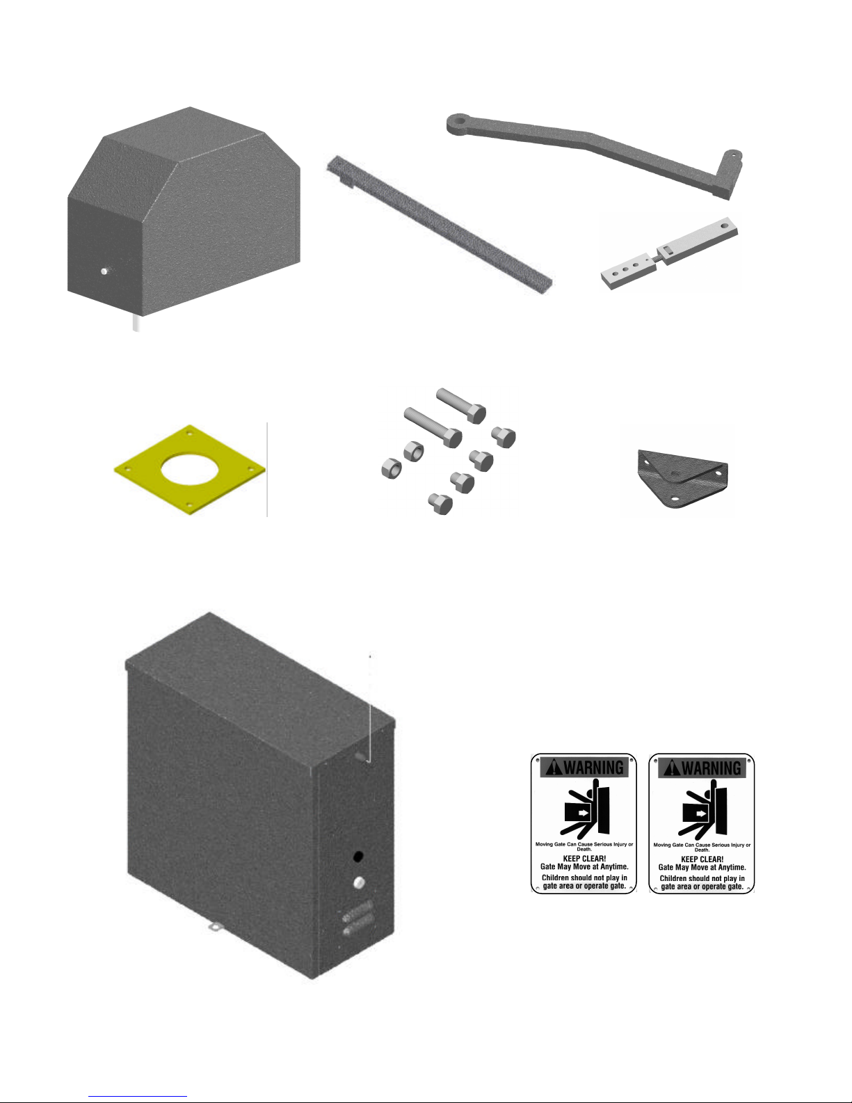
Operator
PARTS IDENTIFICATION
Primary Arm
Secondary Arm
Adjustable Arm
Mounting Plate
Fasteners
Gate Bracket
CAUTION Signs (2 each)
Control Box
Page 7
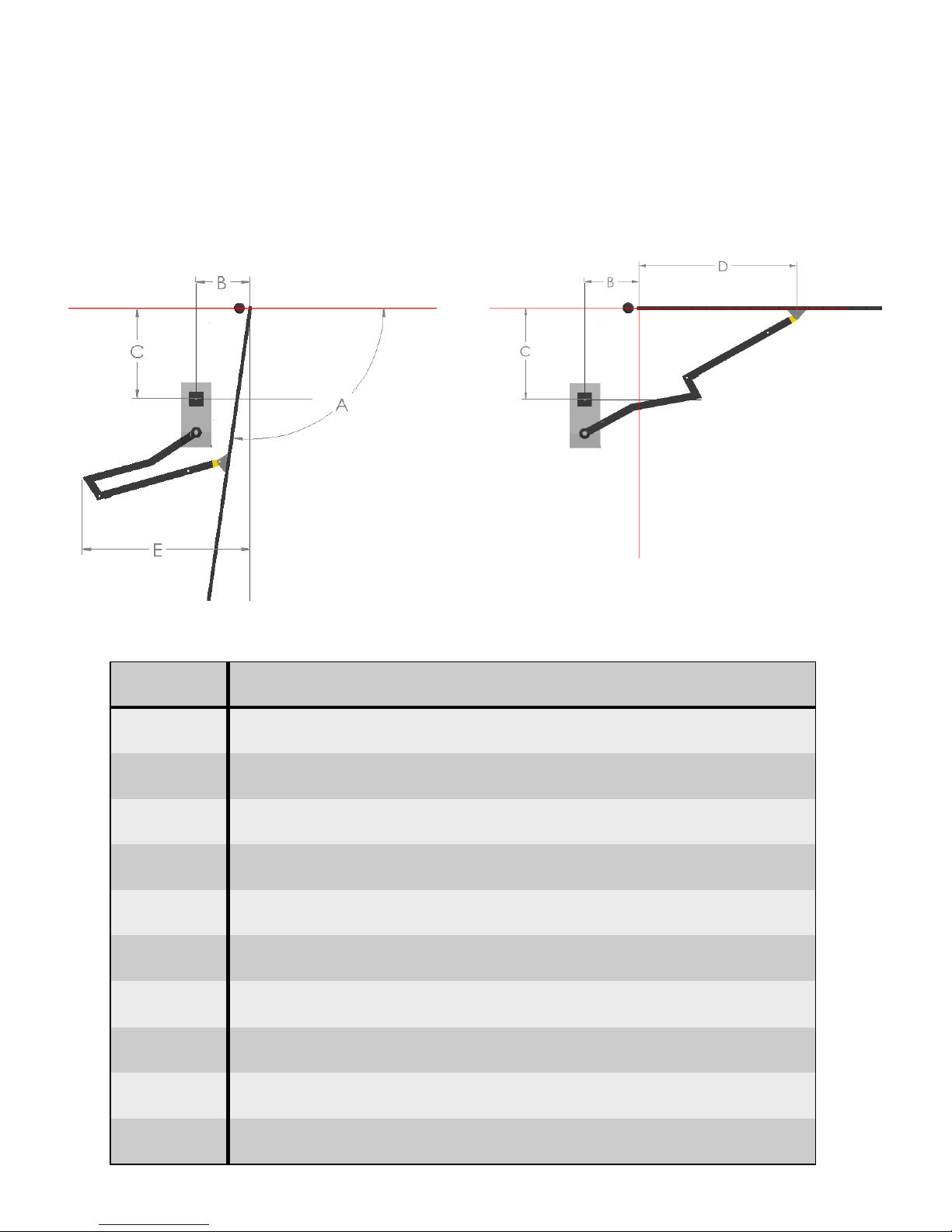
POST LOCATION GUIDE
Determine the angle that the gate will open to (A). Select the post coordinates ( B&C) as shown
on the chart below. Distances are from the hinge square to the center of the mounting post.
Longer gates should operate at the longer speeds.
A
Open degrees
900 10 31.2 46.7 35.3 15
900 10 30 47.5 38 16
920 15 30 42.7 26.2 12
970 13.5 25.5 44.3 46.1 17
970 15 25 45.6 45.6 16
1000 20 25 40.9 37.1 13
1070 20 20 43.2 52.1 17
1100 25 20 35.9 43.8 13
1160 25 15 37.6 56.3 16
B
inches
C
inches
D
inches
E
inches
Approximate
Seconds to open
1170 20 15 43.3 52.9 20
Page 8
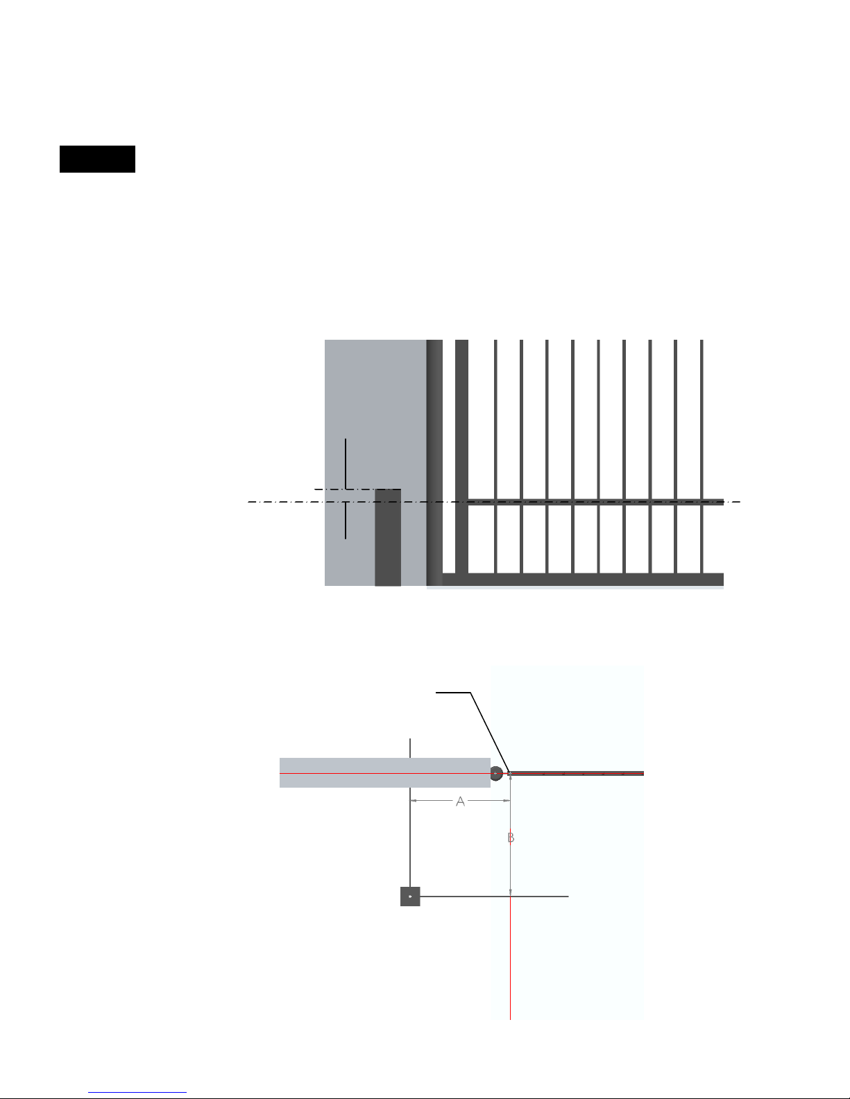
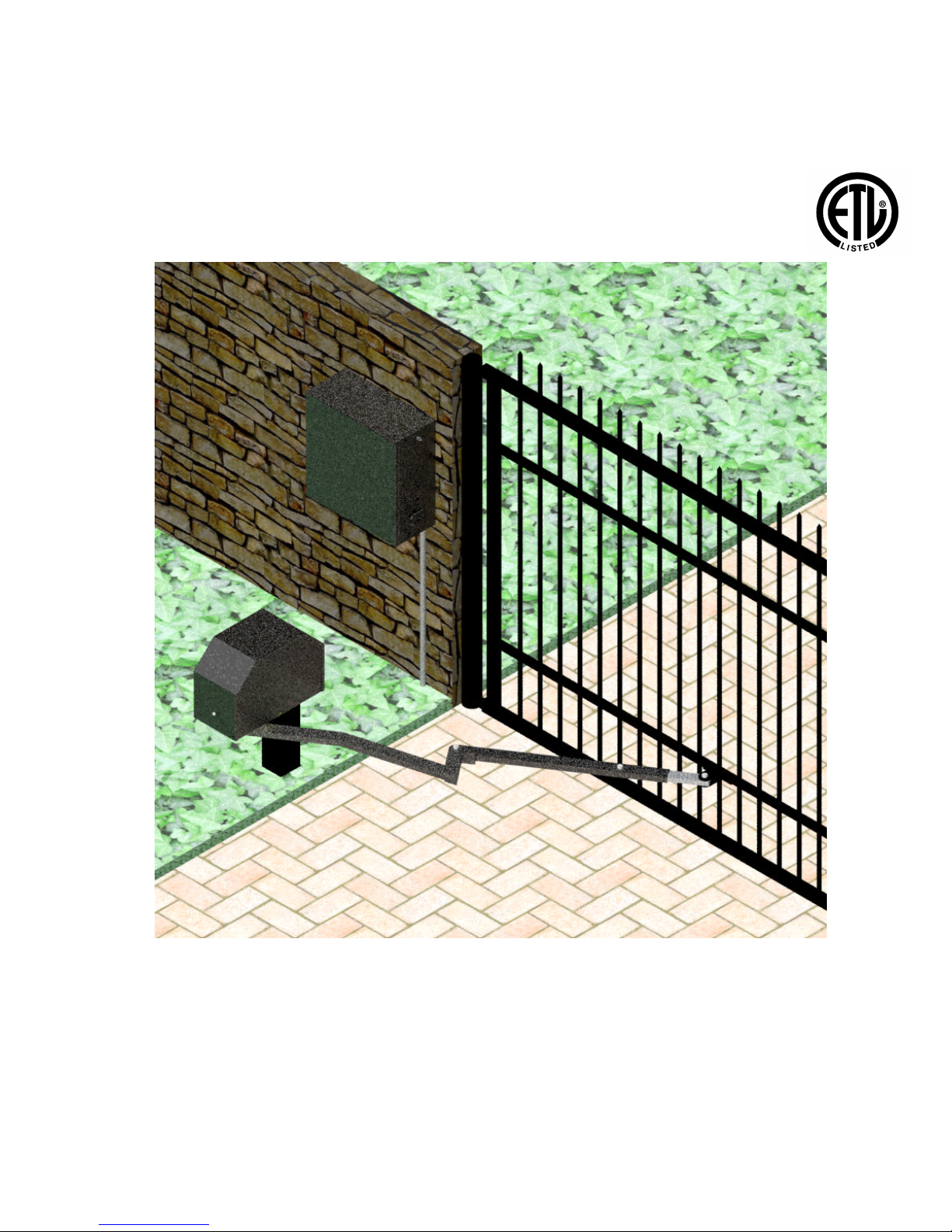
OPERATOR INSTALLATION
STEP 1
The 3500 operator is designed for installation using a 4” x 4” square post
with 1/4” wall thickness.
1. Determine the height on the gate where the operator will attach to.
2. Install the post as per the diagram below. The top of the post should be 2”
above the centerline of the location where the gate bracket will be mounted
on the gate.
3. Conduit should be considered at this time for cable routing from control
box to operator.
Horizontal center line of
where gate bracket is to
be installed
2”
IMPORTANT: The mounting post should be square to the gate in the closed
position and level for proper operation.
Hinge
Wall or Fence
Gate
Distances are
from the hinge to
the center of the
mounting post
Page 9

STEP 2
Mount the control box as close to the operator as possible (recommended within 5
feet). Use mounting hardware capable of
supporting the weight of the control box
with the battery installed.
Do not mount the control box where
the person using the push button on
the side of the box can come in contact with the gate.
Set the battery inside of the control box
with the terminals toward the front. (Do
not use batteries with side terminals.)
STEP 3
Weld the mounting bracket on top of the
mounting post. The bracket should be
level and square to the post.
Tack welds may be made from the top
side of the bracket and post. Bottom
welds should be made for
permanent rigidity.
STEP 4 Lay the operator chassis on it’s side.
The two ears on the primary arm
should point toward the direction the
gate will close. Install the primary arm
to the main drive shaft using the 1/4”
key stock and tighten both set
screws. The collar on the primary
arm should be installed on the shaft
as far as possible.
Primary Arm
Key stock
Two Ears
Page 10

STEP 5
Install the drive unit on the mounting
bracket using (4) 1/2” x 3/4” hex bolts
and lock washers.
STEP 6
Install the secondary arm to the primary arm using a 1/2” x 2-1/4” hex bolt,
brass washers, and lock nut.
The stop tab should be positioned away from the gate.
Stop Tab
STEP 7 Install the adjustable arms to the sec-
ondary arm using the 1/2” x 1-1/2”
hex bolt and nut. Use the middle hole
in the adjustable arm.
Page 11

STEP 7 Install the gate bracket to the adjustable
arm using the 1/2” x 2-1/2” hex bolt,
washers, and lock nut.
STEP 8 Push the arms assembly up against the
gate in the closed position. Make sure
that the primary arm is locked into the
stop tab on the secondary arm. Tack
weld or c-clamp the gate bracket to the
gate. Permanent welds or bolt attachment should be completed once limits
are set.
STEP 9 Route the cable from the control box to the operator. Connect the cable to the
left side of the terminal block on the operator as shown. The operator in this
manual is set up for left side installation (from inside looking at gate in closed
position).
Cable to
Control
Box
Black
Red
Green
Orange
White
Left Side Installation
Cable to
Control
Box
Right Side Installation
Red
Black
Green
White
Orange
Page 12

STEP 10
Connect the two ring terminals on the connector end of the cable to the battery. The
battery charger or solar panel should be installed at this time.
Plug the connector into the Master connector on the circuit board.
STEP 11
Press LED Enable on the right
side of the circuit board.
The gate should be in the closed position. Loosen the set screw on the magnet collar and rotate
until the closed LED illuminates. Tighten the set screw but avoid over tightening (make sure the
magnet in the collar is aligned height wise with the closed limit). Open the gate to the desired
open position and stop the gate. Adjust the open limit screw until the open limit LED illuminates.
Magnet Collar
Limit Switch
Limit Switch
Set Screw
(do not over tighten)
Limit Adjustments
Page 13

STEP 12 The close tension on the gate can be adjusted by:
Removing the 1/2” bolt on the secondary arm
(course adjustment 1”-2”).
Slide the adjustable arm out and rotate counter
clockwise to increase close pressure and clockwise to reduce close pressure.
The three holes in the adjustable arm will allow
further adjustment if necessary.
EMERGENCY MANUAL OPERATION
For manual operation, flip the release switch
on the left underside of the operator.
Pull the arms enough to break over center and open the
gate.
The release switch should be reset for normal operation.
Or
unplug the cable from the control box and plug into the emergency bypass
connector
EMERGENCY BYPASS
Applies battery voltage directly to motor to open gate if
control board fails. User must unplug before gate opens
to maximum travel or 15 amp fuse will open. Fuse
should be checked before returning gate to service.
Page 14

STEP 13
Programming Current Sensing
The 835/836 circuit boards incorporate a safety feature that will put the operator into a hard shutdown mode if the circuit board detects a current sense
two consecutive times during a cycle. This hard shutdown condition can only
be reset by shorting the FIREBOX or UL connectors on the left side of the cir-
cuit board to ground. If a firebox is used in the installation, The firebox door
should be opened and closed to reset the circuit board.
The following instructions must be followed at installation for proper safety assurance.
All limits should be set before beginning this procedure.
This new procedure applies to revision V31 or higher firmware.
1. Press and hold the LED ENABLE button for five seconds. The STOP LED will blink
indicating that the board is in learn mode.
3. Cycle gate for 3 full cycles. The STOP LED will stop blinking indicating that the board
is now ready for normal operation
4. Test the auto reverse sensitivity to ensure maximum safety protection. The current
sensitivity adjustment pot may be adjusted to decrease or increase sensitivity.
COUNTER CLOCKWISE
More sensitivity
Gate is easy to current
sense
CLOCKWISE
Less sensitivity
Gate is harder to
current sense
8. Refer to the 835/836 Operator Control Board Manual to set other options such as
program switch options and close timer adjustments.
Installation is now complete.
Note: Program switch #9 is no longer functional.
Page 15

835/836 Control Board Parts Identification
Program Switches
Optional Device Inputs
Timer To Close -
Dual Gate Delay -
Current Sensitivity -
Adjustments
Microprocessor
GateLink Connector
Remote Monitor Outputs
LED Enable & program
mode push button
Stop Circuit Jumper
Fire & UL Inputs
Emergency Bypass
Actuator Connector
(Slave)
Reverse Battery Polarity
Indicators
Control Board Reset
Optional Device Input
Actuator Connector
(Master)
Page 16

Actuator Connector
Board Actuator Function
7
5
3
1
8
6
4
2
Cable
Pin 1 Orange Open Limit
Pin 2 White Close Limit
Pin 3 Black Motor (positive on open, negative on close)
Pin 4 Red Motor (negative on open, positive on close)
Pin 5 Green Common for both limit switches
Pin 6 Yellow Feedback from intelligent actuator (816E/816EX)
Pin 7 Black Battery Negative
Pin 8 Red Battery Positive
EMERGENCY BYPASS
Applies battery voltage directly to motor to open gate if
control board fails. User must unplug before gate opens
to maximum travel or 15 amp fuse will open. Fuse
should be checked before returning gate to service.
Remote Outputs
12V Supplied battery voltage
SLV Slave Operator Indicator (indicates slave side of gate is closed)
+12V when on closed limit. Ground when off of closed limit.
MAS Master Operator Indicator (indicates master side of gate is closed)
+12V when on closed limit. Ground when off of closed limit.
GND Battery supplied ground
SIREN Connect to siren + (optional)
+12V when gate(s) are running, or in hard shutdown
GND Battery supplied ground
LOCK Connect to lock + (optional) Magnetic or Solenoid type locks (Dip Switch #6 Selectable)
GateLink Connector
Connects control board to a computer using GateLink software. This software
can monitor and diagnose the functions of the microprocessor. Ask your salesperson about this feature.
Page 17

Adjustments
TIMER TO CLOSE Adjusts time before gate automatically closes 1-60 seconds.
DUAL GATE DELAY Adjusts delay between master and slave operation 0-4
(836 only) seconds. (for use with magnetic and mechanical locks.
or stop tabs)
CURRENT SENSITIVITY Increases or decreases the Auto Reverse sensitivity.
Push Buttons
LED ENABLE When depressed, activates LEDs for 15 minutes to
assist in installation and troubleshooting. Hold push
button down for 5 seconds to put in learn mode.
RESET Resets the microprocessor. Returns processor to
last known state.
Jumpers
STOP CIRCUIT JUMPER When the STOP CIRCUIT JUMPER
is connected, the gate will operate normally.
STOP CIRCUIT JUMPER When a 3-button station is connected to
the board, the STOP CIRCUIT JUMPER
must be removed.
Page 18

Program Switches
Setting shown are for
416E, 416EX, 7XXX
operators and 3500
operators.
OFF ON
1 TIMER TO CLOSE Gate does not automatically close. Gate automatically closes.
2 TIMER TO CLOSE OPT. Gate automatically closes from Gate automatically closes only when completely
any position after opening. open (open limit engaged).
3 SLAVE DISABLE Enables slave side (dual gate use). Disables slave side. (single gate use)
4 SIREN DELAY Siren (optional) starts when gate Siren (optional) starts 5 seconds before gate moves.
5 ‘STOP’ CIRCUIT ENABLE Must hold down open or close Normal operation
buttons to move gate. Gate stops Momentary open or close runs gate to limit.
when button released.
6 LOCK TYPE For 12V mechanical (solenoid) locks. For 12V magnetic locks.
(+12V for 4 seconds on open cycle) (+12V when on close limit)
7 COAST ENABLE Gate will brake when at Open or Gate will coast (minimally) when it reaches limits.
Close limit
8 FREE EXIT OPT. A free exit input will open gate from A free exit input will open gate from any
closed position or after a close cycle position after an open or close cycle.
only.
9 LEARN MODE NOT USED
10 SMART ACT. Used for 416E & 416EX actuators, Used for 816E & 816EX actuators
slide gates, 3500 or when slow down (soft start & stop).
feature is not desired.
Page 19

Reverse edge input. When grounded, will stop and reverse gate if closing, resets close timer if gate is open.
Reverse edge input. When grounded, will stop and reverse gate if closing, resets close timer if gate is open.
Optional Device Inputs
GND Supplied Battery Ground
INP Activate Gate (Push button activation when momentarily shorted to ground)
12V Supplied Battery Voltage (Protected with 3 Amp fuse)
GND Supplied Battery Ground
INP Activate Gate (Push button activation when momentarily shorted to ground)
12V Supplied Battery Voltage (Protected with 3 Amp fuse)
EDGE
EDGE
GND Supplied Battery Ground
GND Supplied Battery Ground
STOP Stop input from a 3 button station (must remove STOP CIRCUIT JUMPER) Normally closed
CLOSE Close input from a 3 button station (see program switch #5 for options)
OPEN Open input from a 3 button station (see program switch #5 for options)
GND Supplied Battery Ground
GND Supplied Battery Ground
FREE EXIT Opens gate if closed, stops and reverses gate if closing, resets close timer if gate is open.
GND Supplied Battery Ground
SHADOW Resets close timer when gate is open (also referred to as under gate loop)
GND Supplied Battery Ground
SAFETY Resets close timer if gate is open, stops and reverses if gate is closing. (Does not open a closed gate)
GND Supplied Battery Ground
FIRE When grounded, opens gate and holds gate open until released.
Clears “Hard Shutdown” mode of software.
UL When grounded, opens gate and holds gate open until released.
Clears “Hard Shutdown” mode of software.
GND Supplied Battery Ground
INP Activate Gate (Push button activation when momentarily shorted to ground)
12V Supplied Battery Voltage (Protected with 3 Amp fuse)
Page 20

APOLLO Gate Operators, Inc.
911 Siren
The 911 Siren is included with all Apollo ETL Gate Operators.
Mount siren in an area that will produce maximum performance (additional wire may be required).
Connect the red wire to the SIREN connector on the Remote Monitor Output Connector block.
Connect the black wire to the GND connector on the Remote Monitor Output Connector block.
Red
Black
Set Program Switch # 4 as preferred:
ON - Upon activation, Siren will start for 5 seconds before gate(s) begin moving.
OFF - Siren and gate(s) start immediately upon activation.
NOT USED
Page 21

APOLLO Gate Operators RECEIVER OPTIONS
Do not confuse the receiver code switches with the red program switches on the gate control board.
Never set all code switches to the same position. Transmitters must match code switches for proper operation.
If power is taken directly from battery or connected as shown below, receiver should be configured for 12VDC
Multi-Code/Digi-Code
Allister
Lift-Master
Heddolf
white
1
2
3
4
black
black
gray
gray
red
red
Linear
black
white
yellow
red
white/silver
common
n/o
white/gold
Page 22

TROUBLESHOOTING OPERATOR & ACCESSORIES
Some troubleshooting will require a hand held multimeter. An inexpensive digital multimeter may be
purchased at Radio Shack or a local electric supply company. Refer to the owners manual for
instructions.
SYMPTOM
1. Excessive closing pressure on gate. Re -adjust the close limit switch on the operator.
2. Automatic reverse sensitivity is set too sensitive. Re-adjust - CAUTION: Automatic reverse sensitivity
should be set sensitive enough to avoid injury.
3. Gate is mechanically binding. Disconnect operator from gate and eliminate binding.
4. Battery voltage is too low. Battery voltage should be 12 to 14 volts under load. Check solar panel output or
battery charger output or re-evaluate usage.
5. Replace circuit board.
SYMPTOM
1. Battery voltage is too low. Battery voltage should be 12 to 14 volts under load. Check solar panel output or
battery charger output or re-evaluate usage.
2. Gate is mechanically binding. Disconnect operator from gate and eliminate binding.
3. Current sensitivity is adjusted too sensitive. Re-adjust current sensitivity.
4. Replace circuit board.
Gate opens OK but after closing, opens back up.
Gate moves only a few feet, then stops or reverses.
Page 23

SYMPTOM
1. Code switches do not match. Check that the code switches in the transmitter and the receiver match.
2. Low or dead battery in transmitter. Replace battery.
3. Fuse blown on circuit board. Check fuses on gate control board.
4. Low battery in operator. Battery voltage should be 12 to 14 volts under load.
5. Replace receiver.
Gate will open using push button on side of box, but not with transmitter.
SYMPTOM
Note: Transmission distances will vary according to terrain, obstructions, and electrical interference.
The normal range from inside a vehicle is 50-100 feet while 100 -150 feet may be obtained from outside
the vehicle.
1. Low battery in transmitter. Replace battery.
2. Transmitter malfunctioning. Try a different transmitter.
3. Antenna not making good connection. Be sure center conductor of antenna is penetrating the female
connector on the side of the gate box.
4. Reception is being blocked. Raise the height of the antenna using a #244 antenna extension kit.
5. Replace receiver.
SYMPTOM
Transmitter works, but not very far.
Gate randomly opens, closes, or stops for no reason.
1. Transmitter is stuck on. Check all transmitters, keypads, pushbuttons, etc. for a stuck button.
2. Transmitter and receiver code switches are all down, up, or in the middle. Change at least one switch
position in the transmitter and receiver.
3. Push button on side of control box is defective. Disconnect and test.
Page 24

SYMPTOM
Gate will not open or close.
Short the GND and UL connections on the lower left set of connectors and test.
Disconnect the solar panel or charger and measure the battery voltage. Battery should read 12 or more volts and
never drop below 11 volts when gate is operating.
Reset program switches to factory settings . .
Single Boards
# 1, # 2, # 3, # 5, # 9, ON, all others OFF
Dual Boards
# 1, # 2, # 5, # 9 ON, all others OFF
*Be sure to turn Switch # 9 OFF during normal operation.
1 ON
2 ON
3 ON
4 off
5 ON
6 off
7 off
8 off
9 NOT USED
10 off
Disconnect all accessories from the circuit board - receivers, push buttons, keypads, loops, phones, intercoms, etc.
Activate the operator by momentarily shorting GND to INP
on one of the three pin connectors.
If the operator works, reconnect each accessory individually
starting with push button and test operation.
Disconnect operator from circuit board and inspect pins in the connector for damage or
poor connections.
Check for proper limit switch configuration (multimeter required) on the cable from
the operator to the control box :
GATE IN OPEN POSITION .......Orange & Green wires are shorted, White & Green wires are open.
GATE IN CLOSED POSITION ..White & Green wires are shorted, Orange & Green wires are open.
GATE IN MID TRAVEL ............ White, Green, & Orange wires are open, no shorts.
Replace circuit board.
Page 25

LIMITED TWO -YEAR WARRANTY
Apollo Gate Operators are warranted against defects for a period of 24
months from the date of purchase, providing recommended installation
procedures are followed. This warranty is in lieu of all other warranties
expressed or implied (some states do not allow limitations on how long an
implied warranty lasts, so this limitation may not apply to you) and shall be
considered void if damage was due to improper installation or use, connection
to improper power source, or if damage was caused by fire, flood, or lightning.
The manufacturer will not be responsible for any labor charges incurred in the
removal or replacement of defective parts.
In case of failure due to defective material or workmanship during the
warranty period, the defective part will be repaired or replaced at the
manufacturer’s option at no charge if returned freight prepaid. New or factory
rebuilt replacements may be used. Replacement parts are warranted for the
remaining portion of the original warranty period. The manufacturer will pay
standard ground freight on the return of repaired or replaced items in warranty.
 Loading...