

Page 1
APOLLO 120 /150 III
12.1”/15.0”/15.1” TFT Intel®
Celeron/Pentium® III
Plastic-housing Panel PC with
Versatile
Stand design
User’s Manual (Version 2305)
Page 2

Copyright Notice
This document is copyrighted 2003 by the Manufacturer.
The information provided in this document has been
carefully checked and is accurate at the time of publication.
However, the Manufacturer assumes no responsibility for
any infringements of patents or other rights of third parties
that may result from its use.
No part of this publication may be reproduced, stored in a
retrieval system, or transmitted in any form of or via any
means without the prior written permission of the
Manufacturer. Further, this publication and features
described herein are subject to change without notice.
Trademarks
All brand and product names used for identification in this
document are trademarks or registered trademarks of their
respective companies.
© Copyright 2003, May Version 2305
All rights reserved.
Printed in Taiwan
Page 3

Unpacking
After unpacking the APOLLO 120/150 III carton, check
and see if the following items are included and in good
condition.
u APOLLO III main system x 1
u Accessories
- Power cord (90o) x 1
- External FDD cable (optional) x 1
- External 5V/12V DC power cable (optional) x 1
- Utilities & drivers & user manual CD diskette x 1
(for touchscreen drivers, please download the
updated drivers from the following website
http://www.3m.com or
http://www.elotouch.com or
http://www.eturbotouch.com
- Base knob with rubber cushion x 1
- Panel mounting kit (optional) x 1 set
Make sure that all of the items listed above are present. If
any of the above items is missing, contact your dealer
immediately.
Warranty
All products manufactured by the Manufacturer. are
warranted against defective materials and workmanship for
one year starting from the date of delivery to the original
purchaser. However, warranty or service will not be
extended if 1). the product is repaired, modified or altered
unless such repair, modification or alteration is authorized
by the Manufacturer; or 2). the product serial number or
warranty label is defaced or missing; or 3). the product is
not properly used.
Page 4

Important Safety Precautions
Before getting started, read these instructions and save
them for later reference.
1. Turn off the computer before cleaning. Clean with a
damp or dry cloth only. Do not spray any liquid cleaner
on screen directly.
2. The power outlet socket used to plug in the computer
power cord must be located near the system and easily
accessible. Do not use outlets on the same circuit of
the systems that regularly switched on and off.
3. Make sure the voltage of the power source is correct
before connecting the computer to the power outlet.
4. If the computer is sharing an extension cord with other
devices, make sure the total ampere rating of the
devices plugged into the extension cord does not
exceed the cord’ s ampere rating.
5. Do not expose the power cord, extension cord and
power outlet to moisture.
6. Install the computer on a reliable surface to prevent
damage caused by dropping.
7. This computer is not equipped with an operating
system. An operating system must be loaded first
before installing any software into the computer.
8. Disconnect the power cord from the computer before
any installation. Make sure both the computer and the
external devices are turned off. The sudden surge of
power may ruin any sensitive components. Also make
sure the computer is properly grounded.
9. During installation of any internal components, be sure
to ground yourself to keep from any static charge.
Most electronic components are sensitive to the static
electric charge. Use a grounding wrist strap and place
all electronic components in any static-shielded
devices.
Page 5

10. The openings on the computer enclosure are for the
cabin ventilation to prevent the computer from
overheating. DO NOT COVER THE OPENINGS.
11. The brightness of the flat panel display will decrease
with use. However, hours of use will vary depending on
the application environment.
12. If the computer is equipped with a touch panel, avoid
using sharp objects to operate the touch panel.
Scratches on the touch panel may cause
mal-calibration or non-function to the panel.
13. The LCD panel display is not subject to shock or
vibration. When assembling the computer, make sure
it is securely installed.
Page 6

Table of Contents
1. INTRODUCTION............................................. 1-1
1.1. GENERAL INFORMATION ..................................1-2
1.2. WHAT COVERS IN THIS MANUAL.........................1-3
1.3. SPECIFICATIONS...........................................1-5
1.4. DIMENSIONS .............................................1-10
1.4.1. APOLLO 120 ........................................1-10
1.4.2. APOLLO 150 ........................................1-11
2. USING THE SYSTEM.....................................2-13
2.1. IDENTIFYING THE SYSTEM..............................2-14
2.1.1. Front View...........................................2-14
2.1.2. Side Views...........................................2-15
2.1.3. I/O Outlets..........................................2-16
2.2. SYSTEM SETUP FOR THE FIRST-TIME USE ............2-17
2.2.1. Installation Procedures..........................2-17
2.2.2. Running the BIOS Setup .......................2-18
2.2.3. Operating System and Driver Installation 2-19
3. VERSATILE STANDING & MOUNT OPTIONS . 3-21
3.1. VERSATILE STAND .......................................3-22
3.1.1. Standing Upright..................................3-22
3.1.2. 45 to 900 Free Standing ........................3-22
3.1.3. Fixed Standing.....................................3-23
3.1.4. Cable Management...............................3-24
3.2. WALL MOUNTING AND MOBILE APPLICATIONS.......3-25
3.3. PANEL MOUNTING .......................................3-27
3.4. KIOSK INTEGRATION ..................................3-28
Page 7

4. I/O CONNECTION........................................ 4-29
4.1. PARALLEL PORT ..........................................4-30
4.2. COM PORTS X 4 ........................................4-31
4.3. 100/10 BASE-T ETHERNET (RJ-45)................4-33
4.4. VGA INTERFACE.........................................4-33
4.5. 2
ND
DISPLAY GRAPHIC SUPPORT MODE...............4-34
4.5.1. When System Memory Clock = 66MHz....4-34
4.5.1.1. Single Display Mode........................4-35
4.5.1.2. Mirror Display Output Mode..............4-36
4.5.1.3. Multiple Display Output Mode ...........4-37
4.5.2. When System Memory Clock = 100MHz ..4-38
4.5.2.1. Single Display Mode........................4-38
4.5.2.2. Mirror Display Output Mode..............4-39
4.5.2.3. Multiple Display Output Mode ...........4-40
4.5.3. When System Memory Clock = 133MHz ..4-41
4.5.3.1. Single Display Mode........................4-42
4.5.3.2. Mirror Display Output Mode..............4-43
4.5.3.3. Multiple Display Output Mode ...........4-44
4.6. PS/2 KEYBOARD INTERFACE...........................4-45
4.7. PS/2 MOUSE INTERFACE...............................4-45
4.8. EXTERNAL FDD (DB-15) .............................4-46
4.9. +5V/12V DC-OUT ....................................4-47
4.10. VR BRIGHTNESS CONTROL ............................4-47
4.11. DIO (DIGITAL INPUT & OUTPUT) ....................4-48
4.12. AUDIO INTERFACE (LINE-IN, MIC-IN, SPK-OUT) .4-50
4.13. USB PORTS..............................................4-50
4.14. IR KEYBOARD SENSOR (OPTIONAL) ..................4-50
4.15. AC/DC INLET/POWER SWITCH .......................4-50
Page 8

5. HARDWARE INSTALLATION AND UPGRADE. 5-51
5.1. RECOGNIZING THE SYSTEM MAJOR PARTS ...........5-53
5.2. INSTALLING THE CPU...................................5-55
5.3. INSTALLING THE SDRAM MEMORY MODULE ........5-56
5.4. MOTHERBOARD ASSEMBLY .............................5-57
5.5. TOUCH CONTROLLER ASSEMBLY .......................5-58
5.6. HDD MODULE ASSEMBLY ..............................5-59
5.7. TOUCHSCREEN OR FRONT BEZEL ASSEMBLY .........5-60
5.8. LCD MODULE ASSEMBLY...............................5-62
5.9. CD-ROM/DVD-ROM/FDD MODULE ASSEMBLY ..5-67
5.9.1. Internal CD-ROM/FDD Assembly ............5-67
5.9.2. External FDD Connection.......................5-69
5.10. POWER MODULE ASSEMBLY ............................5-70
5.11. EXPANSION OUTLETS & RISER CARD ASSEMBLY....5-72
5.12. BACK PANEL ASSEMBLY.................................5-73
5.13. STAND MODULE ASSEMBLY.............................5-74
6. SYSTEM MOTHERBOARD & I/O BOARD........ 6-77
6.1. APOLLO III MOTHERBOARD..........................6-78
6.1.1. General Information .............................6-78
6.1.2. Specifications.......................................6-79
6.1.3. Locating Jumpers & Connectors..............6-81
6.1.4. Jumpers & Jumper Setting.....................6-82
6.1.4.1. DOC 2000 Address Setting (JP1).......6-83
6.1.4.2. Clear CMOS (JP2) ...........................6-83
6.1.4.3. COM 2 232/422/485 Setting ............6-83
Page 9

6.1.5. Connectors & Pin Assignment.................6-84
6.1.5.1. PWR3: ATX Power connector ............6-85
6.1.5.2. J2: CD Audio IN.............................6-86
6.1.5.3. J7: HDD LED & ACPI LED & SMI........6-86
6.1.5.4. J8: IR / CIR Connector ....................6-86
6.1.5.5. J9: Power LED & KB ........................6-87
6.1.5.6. SW1: ATX Power ON/OFF & Reset .....6-87
6.1.5.7. COM3............................................6-87
6.1.5.8. LCD1: LCD Connector......................6-88
6.1.5.9. INV1: LCD Inverter Connector.........6-89
6.1.5.10. FDD1: FDD connector.....................6-89
6.1.5.11. IDE1/IDE2: Primary/Secondary HDD.6-90
6.1.5.12. SCSI 1: PRT/Serial Port/DIO Port......6-91
6.1.5.13. SCSI 2: KB/MS/VGA/LAN USB/FDD...6-92
6.1.5.14. CN4: PCI/ISA Expansion Slot............6-93
6.2. APOLLO III I/O BOARD ..............................6-96
6.2.1. Locating Jumpers & Connectors..............6-96
6.2.2. Jumpers & Jumper Setting.....................6-97
6.2.2.1. JP1: Keyboard Power Select ............6-97
6.2.2.2. COM port Power Selection................6-97
6.2.3. Connectors & Pin Assignment.................6-98
6.2.3.1. KB1: PS/2 Keyboard Connector ........6-99
6.2.3.2. KBMS: PS/2 Mouse .........................6-99
6.2.3.3. COM1, COM2, COM4: DB-9 .............6-99
6.2.3.4. CN1: DC Power Output.................6-100
6.2.3.5. LPT1: D-SUB-25 Parallel Port.......... 6-100
6.2.3.6. CRT1: VGA (D-SUB 15 Pin) ............6-100
6.2.3.7. FDD1: External FDD Connector.....6-101
6.2.3.8. J11: USB 1 , USB2 Connector.......6-101
6.2.3.9. DIO1: RJ-11 Connector ................. 6-101
6.2.3.10. LAN1: RJ-45 Ethernet Connector .... 6-101
6.2.3.11. MIC1........................................... 6-102
6.2.3.12. LINE 1......................................... 6-102
6.2.3.13. SPK 1.......................................... 6-102
6.2.3.14. SCSI 1: PRT /Serial Port/DIO Port...6-103
6.2.3.15. SCSI 2: KB/MS/VGA/LAN USB/FDD. 6-104
Page 10

7. AWARD BIOS SETUP.................................. 7-105
7.1. AWARD BIOS..........................................7-106
7.2. CONTROL KEY DEFINITION........................... 7-107
7.3. GETTING HELP .........................................7-108
7.3.1. Main Menu......................................... 7-108
7.4. AWARD BIOS SETUP ............................... 7-108
7.4.1. AWARD BIOS Setup Main Menu............7-108
7.4.2. Standard CMOS Features.....................7-110
7.4.3. Advanced BIOS Features..................... 7-113
7.4.4. Advanced Chipset Features..................7-117
7.4.5. Integrated Peripherals ........................ 7-123
7.4.6. Power Management Setup...................7-127
7.4.7. PnP/PCI Configuration.........................7-131
7.4.8. PC Health Status ................................ 7-133
7.4.9. Frequency Voltage Control................... 7-134
7.4.10. Load Fail-Safe Defaults .......................7-136
7.4.11. Load Optimized Defaults......................7-137
7.4.12. User Password ...................................7-138
7.4.13. Save and Exit Setup ...........................7-139
7.4.14. Exit Without Saving............................7-140
8. SOFTWARE & DRIVERS INSTALLATION ..... 8-141
8.1. ETHERNET DRIVERS................................... 8-142
8.2. PC 610 AGP XGA................................... 8-143
8.3. AUDIO SETUP .......................................... 8-144
8.4. TOUCHSCREEN DRIVERS .............................. 8-145
8.5. DRIVER INSTALLATION................................ 8-146
APPENDIX .....................................................8-147
A: LCD SPECIFICATION.........................................8-147
B: DISKONCHIP INSTALLATION.............................. 8-150
C: WAKE-ON-LAN ..............................................8-152
D: FIRST MB MEMORY MAP.................................... 8-155
E: POWER SUPPLY................................................8-156
Page 11

User Manual version 2305
1. INTRODUCTION
This chapter provides background
information and detail specification on
the APOLLO 120/150 III. Sections in this
chapter include:
u General Information
u What covers in this Manual
u Specification
u Dimension
APOLLO 120/150 III
1-1
Page 12

User Manual version 2305
1.1. General Information
The information revolution which started from the mid ’90
inaugurated a new competitive era where consumercomputing technology was exploited to business operation
quicker than ever before. Many enterprises from our life
related industries such as POS, POI, KIOSK, Banking,
Medical to the high-tech Telecom, Aerospace,
Semiconductor … etc. all are eager or forced to automate
their industries with PCs in order to thrive in this new age. For
their industrial automation, there is one thing in common, i.e.
space is always a premium and system stability is always a
must in their environmental applications.
The APOLLO 120/150 is a 12.1"/15.0” or 15.1" TFT Intel
Celeron/Pentium III/Pentium IV plastic-housing multimedia
panel PC system. With a 150W or 200W ATX power supply as
its engine, the APOLLO is a genuine P4 panel PC designed for
high performance multimedia application. Featuring with
versatile stand design for different environmental
applications, the APOLLO itself can be used as a
ready-to-play system by connecting to necessary peripherals.
By integrating the APOLLO system to the special designed
HERCULUS KIOSK, the complete system is widely used for
KIOSK integration. It also provides 2 sets of VESA holes for
market-available swing arms for mobile application. Also with
the availability of both AC and DC systems, the APOLLO is the
best turnkey solution platform for any system integration.
In terms of panel size, the APOLLO has 12.1” and 15.0” or
15.1” systems. In terms of system engine, the APOLLO also
have two versions, one APOLLO III, Celeron/Pentium III
system and the other APOLLO IV, Pentium IV system. To
upgrade the system, simply replace the motherboard.
Fully configurable and with its sleek outlook, the APOLLO is
an ideal platform for any space-constricted application.
1-2
APOLLO 120/150 III
Page 13

User Manual version 2305
1.2. What Covers in this Manual
This handbook contains most information you need to set up
and use the APOLLO III system. You do not need to read
everything in this handbook to use the system.
For a quick start, see the following chapter summaries;
Chapter 1 (the current chapter) provides background
information and detail specification on the
APOLLO 120/150 III.
Chapter 2 identifies the APOLLO III system exterior
components and provides instructions to help
you to use the system as soon as possible.
Chapter 3 details the panel PC’s various standing and
mounting options by graphical illustrations.
Chapter 4 provides the procedures to connect external
devices to the I/O interface
Chapter 5 helps you to recognize the APOLLO system
internal components. It also provides the
installation procedures including LCD,
touchscreen, power supply module, CPU, system
memory, FDD, HDD and CD-ROM drive.
Chapter 6 provides detail information of the jumper settings
and connector signals of the system control
board.
Chapter 7 explains the AWARD BIOS setup.
Chapter 8 introduces the Ethernet, XGA and audio drivers.
Chapter 9 details the procedures to install the touchscreen
software drivers under DOS and Windows
operation
APOLLO 120/150 III
1-3
Page 14

User Manual version 2305
Appendix A details the 12.1”/15.0” or 15.1” LCD
specifications.
Appendix B introduces the DiskOnChip installation.
Appendix C introduces the Wake-On-LAN feature.
Appendix D explains the first MB memory map.
Appendix E provides the specifications for the built-in power
supply.
1-4
APOLLO 120/150 III
Page 15

User Manual version 2305
1.3. Specifications
APOLLO: 12.1”/15.0” or 15.1” TFT Intel® Celeron/Pentium®
III Plastic-housing Panel PC with Versatile Stand
design
SYSTEM
Flat Panel
u APOLLO 120: 12.1” color TFT, 800*600
Viewing angle 100
Luminance (cd/m2) 150 or above
Simultaneous mode yes
u APOLLO 150: 15.0”/15.1” color TFT, 1024*768
Viewing angle 120
Luminance (cd/m2) 250/200 or above,
optional high-luminance
model
Simultaneous mode yes
CPU (Socket 370)
u Intel Pentium III FCPGA 1GHz/133MHz
u Intel Pentium III FCPGA 650-933/133MHz
u Intel Pentium III FCPGA 500E-850E/100MHz
u Intel Celeron FCPGA 800MHz-1.10GHz/100MHz
u Intel Celeron FCPGA 533AMHz-766MHz/66MHz
u Intel Celeron PPGA 300A-533MHz/66MHz
System Chipset
u SiS 630ST
System BIOS
u Award PnP Flash BIOS
System Memory
u 1*168pin DIMM socket supporting SDRAM up to 512MB
L2 Cache
u CPU built-in
APOLLO 120/150 III
1-5
Page 16

User Manual version 2305
Standard I/O
u Serial ports*4: COM 1, 2 & 4 with +5V/12 power output
on pin #9, COM 3 internal type reserved for touchscreen,
COM2 RS-232/485 jumper selectable
u Parallel Port*1: supports SPP/EPP/ECP
u External FDD Interface*1
u +5V/+12V DC-out*1
u PS/2 Keyboard Interface*1
u PS/2 Mouse Interface*1
u DIO: Input*2, output*2
u USB Interface*2
u VGA Interface*1
u Brightness VR*1
u Speaker-out, MIC-in, Line in
Ethernet
u 100/10 Base-T Ethernet with RJ-45 phone jack
u Supports WAKE-ON-LAN
Watchdog Timer
Display
u Integrated 2D/3D graphics engine, 4X AGP
u Share system memory architecture able to utilize the
display memory size up to 64MB
u Supporting LCD/VGA dual display mode (under
Windows 98 and Windows ME and Windows XP)
1-6
APOLLO 120/150 III
Page 17

User Manual version 2305
Audio Function
u Full duplex and independent sample rate converter for
audio recording & playback
u Supports Microsoft DirectSound
u 3D positional audio effects
u Hi-performance, mixed-signal, stereo
u MIC-In, Speaker-Out, Line-In
u Pin header for CD-audio in
Hardware Monitor
u Monitoring processor & system
u Monitoring 5VSB, VBAT, 1.5V, 3.3V, +5V, +12V, -12V, and
processor voltages
u Monitoring processor, chassis fan speeds
u Controlling processor and chassis fan speed and failure
alarm
u Automatic fan on/off control
u Read back capability that displays temperature, voltage
and fan speed
u Supporting Intel processor thermal diode output (real
processor temperature)
Expansion Slot
u PCI*2 or PCI*1 + ISA*1
u Expansion card size (L*W)
PCI card: max. 190*120 mm
ISA card max. 190*120 mm if no internal FDD is
installed; 170*120 mm if internal FDD is installed
Front Bezel
u LED indicators for HDD, LAN, POWER
u IrDA receiver (optional)
APOLLO 120/150 III
1-7
Page 18

User Manual version 2305
PERIPHERAL & STORATE DEVICES
Touchscreen (optional, sharing COM3)
u 12.1”/15.1” analog resistive type with RS-232 controller
u 12.1”/15.1” capacitive type with RS-232 controller
u 12.1”/15.1” surface acoustic wave type (SAW)
Power Supply
u ATX 150W, input range: 100~240V/5A @60Hz,
200~240V/2.5A @50Hz
u DC 150W, 20~28VDC, 40~56VDC or DC 200W, 36~72VDC
(optional)
Speakers
u Water-proof speakers*2
CD-ROM or CD-RW or DVD-ROM or COMBO
u Slim type*1 (optional) or
u External type via USB
Floppy Disk Drive
u Slim type*1 (optional) or
u Via external FDD or
u External type via USB
Hard Disk Drive
u 3.5" HDD*1 (optional) or 2.5” HDD x 2 (optional)
1-8
APOLLO 120/150 III
Page 19

User Manual version 2305
MECHANICAL & ENVIRONMENTAL
Construction
u Inside: heavy-duty steel
u Outside: fire-proof resilient ABS/PC plastic
Color (standard)
u Beige
u Black
Dimension (chassis only, unit: mm)
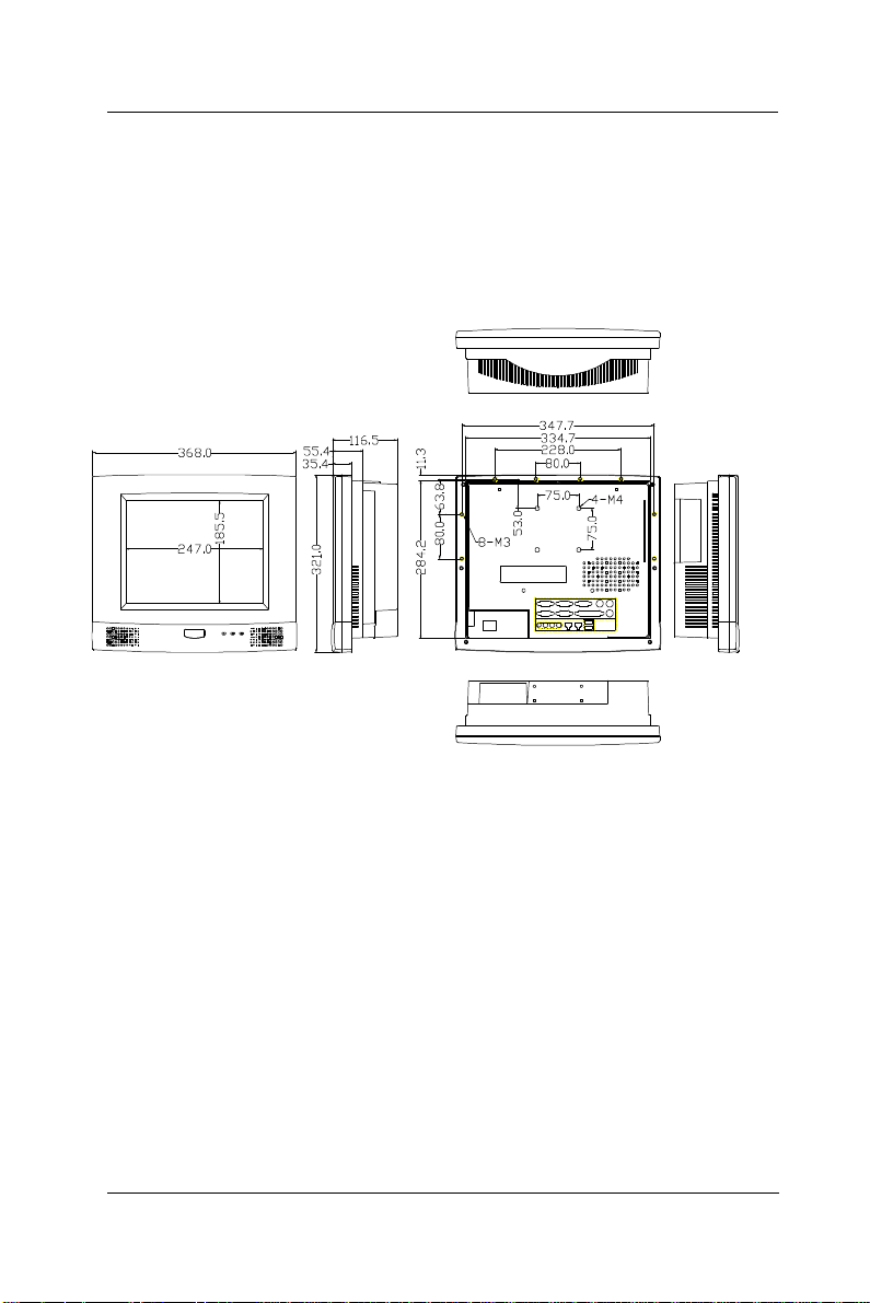
u APOLLO 120: 368*321*116.5 (L*W*D);
334.7*284.21 (for panel mount)
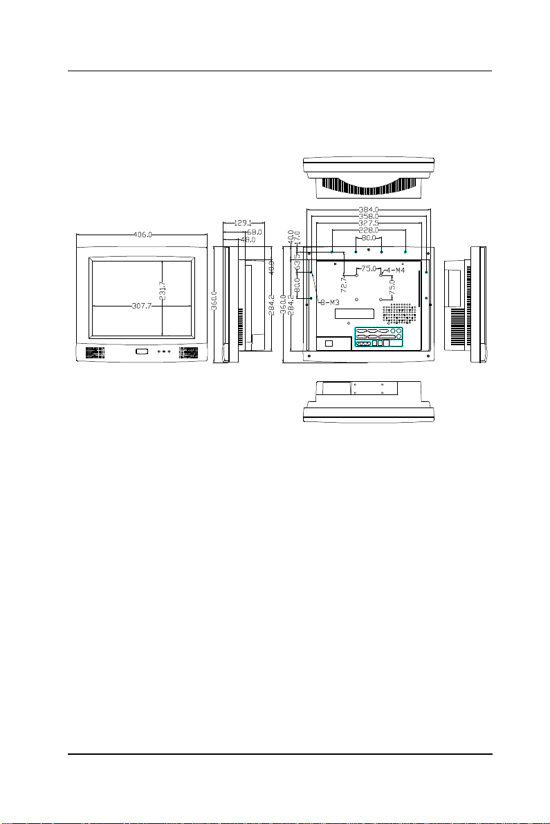
u APOLLO 150: 406*360*129 (L*W*D);
384*284.2 (for panel mount)
Mounting
u Panel mount with mounting kits
u Wall mount with swing arm: standard VESA mounting
holes (75*75 mm)
Versatile Stand
u 45~90o free standing
u Avocado-shape holes for fixed standing
u Cable Management design
§ Specifications are subject to change without notice.
APOLLO 120/150 III
1-9
Page 20
User Manual version 2305
10
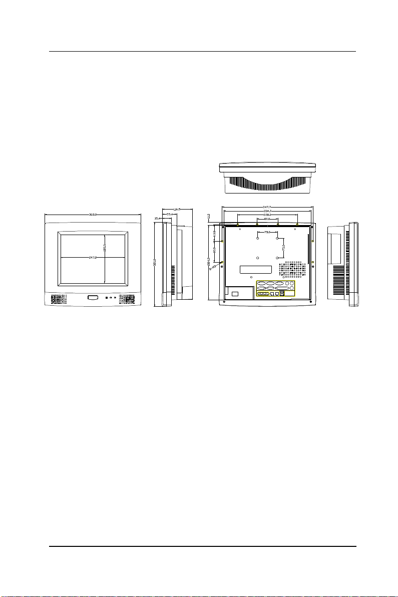
1.4. Dimensions
1.4.1. APOLLO 120
The APOLLO 120’s chassis size is shown below. This does not
include the dimension of the stand. This does not include the
dimension of the stand.
1-
Figure 1-1: APOLLO 120 DIMENSION
APOLLO 120/150 III
Page 21
User Manual version 2305
1.4.2. APOLLO 150
The APOLLO 150’s chassis size is shown below. This does not
include the dimension of the stand.
Figure 1-2: APOLLO 150 DIMENSION
APOLLO 120/150 III
1-11
Page 22

User Manual version 2305
2-12
APOLLO 120/150 III
Page 23

User Manual version 2305
2. USING THE SYSTEM
u Identifying the APOLLO system
u System setup for the first-time use
APOLLO 120/150 III
2-13
Page 24
User Manual version 2305
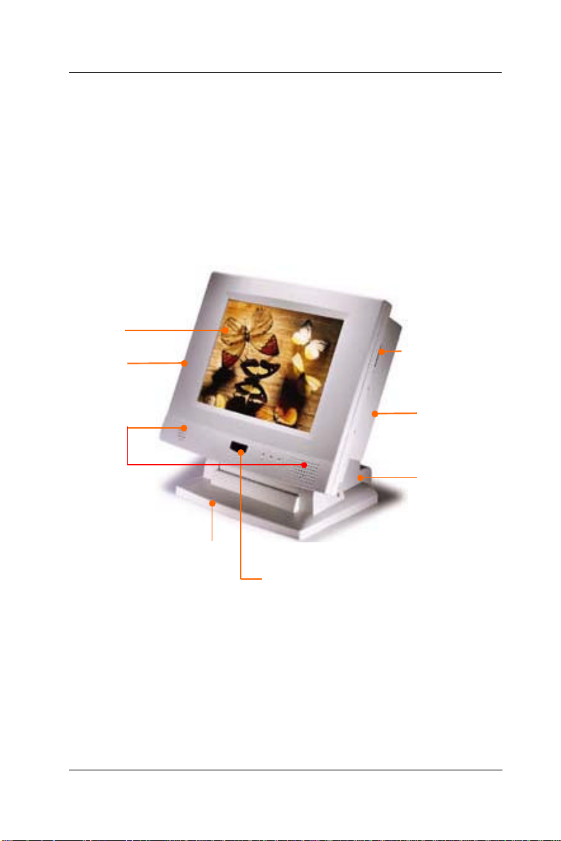
12.1”/ 15.1” LCD
PCI/ISA expansion outlet
able management
2.1. Identifying the System
Before getting started, take a moment to familiarize yourself
with the system and the I/O arrangement of the APOLLO
120/150.
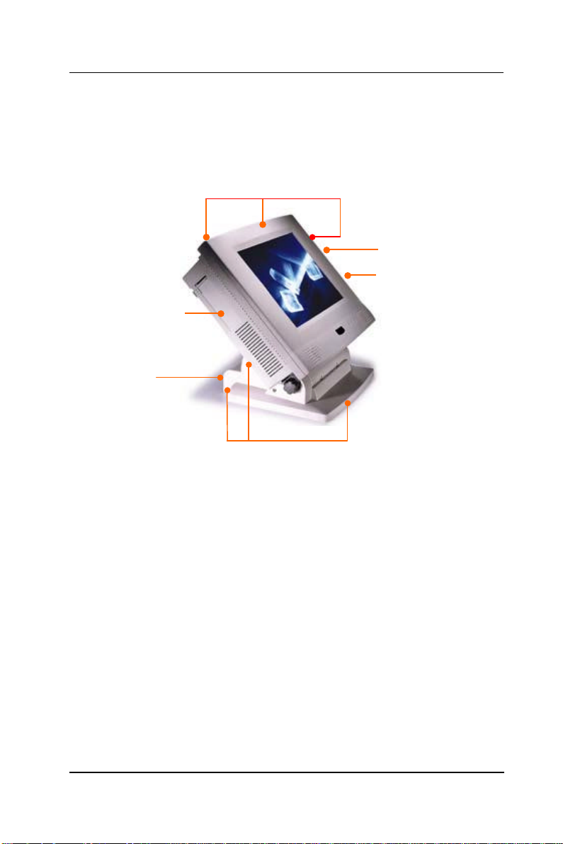
2.1.1. Front View
When the APOLLO 120/150 is put upright on the desktop with
the provided pedestal, its front view appears as below.
The illustrations of the APOLLO 120/150 may differ slightly
because the APOLLO system series has two different LCD size:
12.1” & 15.1”.
& touchscreen
Side door for two
Speaker
Versatile stand for
desktop standing
Wireless KB sensor or
Motion sensor or IrDA
FDD drive &
CD-ROM drive
Fire-proof
resilient plastic
C
covers
2-14
APOLLO 120/150 III
Page 25
User Manual version 2305
2.1.2. Side Views
The left side of the panel PC appears as below:
Side door for two PCI/ISA
expansion outlet
Cable management
cutout
Screw holes for peripheral
device attachment
Base covers +pedestal = versatile stand
Floppy disk drive
CD-ROM
APOLLO 120/150 III
2-15
Page 26
User Manual version 2305
P
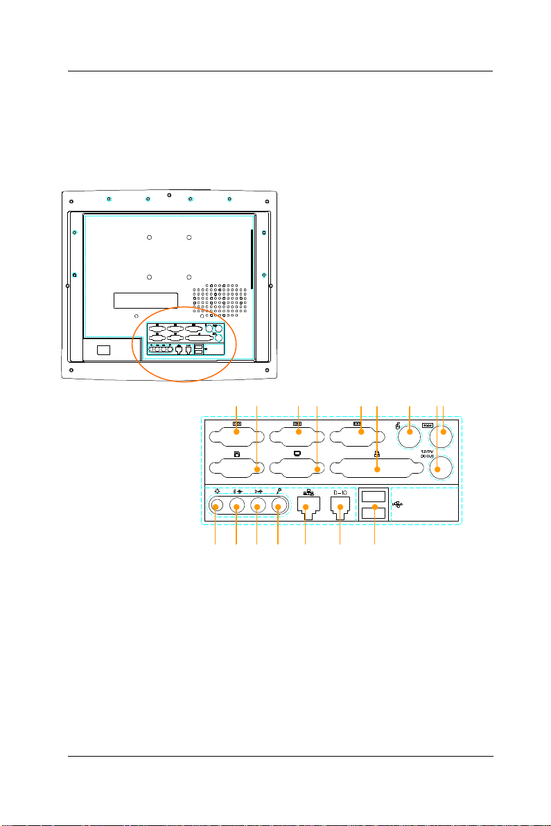
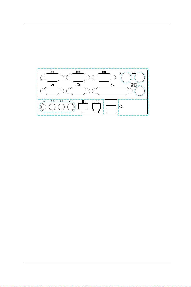
2.1.3. I/O Outlets
When you turn around the APOLLO system, you will find the
power switch and all the I/O ports are located at the rear
cover of the panel PC.
A. COM 4 B. EXTERNAL FDD C. COM 2
D. VGA PORT E. COM 1 F. PRINTER PORT
G. PS/2 MOUSE H. +5/12V DC-OUT I. PS/2 KEYBOARD
J. VR BRIGHTNESS K. SPEAKER-OUT L. LINE-IN
M. MIC-IN N. ETHERNET (RJ-45) O. 2-CHANNEL DIO
P. USB*2
4 2 1
A B C D E F G H I
4 2 1
J K L M N O
2-16
APOLLO 120/150 III
Page 27

User Manual version 2305
2.2. System Setup for the First-time Use
To set up the APOLLO 120/150 for the first-time use, you
should have the following items ready. The items are either
in the accessory box or available in any computer stores.
u 110V or 220V power cord
u PS/2 or AT keyboard or wireless keyboard
u PS/2 or serial mouse
2.2.1. Installation Procedures
The APOLLO system can be powered either by an AC
electrical outlet (100~240V/5A @60Hz, 200~240V/2.5A @50Hz)
or by DC power source (20~28VDC or 40~56VDC or 36~72VDC).
If the system is to be powered up by AC power, be sure to use
the right power cord (110V or 220V) for connection.
1. Connect the female end of the power cord to the AC inlet
located at the rear bottom side of the panel PC.
2. Connect the 3-pin male end of the power cord to an
electrical outlet.
3. Connect a PS/2 keyboard or an AT keyboard to keyboard
port. If you are using an AT keyboard, you need an
adapter (AT to PS/2 KB) for this connection.
4. Connect the PS/2 mouse to the PS/2 mouse port. If you
are using a serial mouse, it can be connected to the COM
port.
5. Turn on the main switch on the power supply if there is
one.
6. Power on the panel PC by switching the power switch
located at the rear bottom side.
APOLLO 120/150 III
2-17
Page 28

User Manual version 2305
2.2.2. Running the BIOS Setup
If you are a commercial user, the APOLLO 120/150 III should
have been properly set up and configured by your dealer. You
may still find it necessary to change the system configuration
information. In this case, you need to run the system’s BIOS
setup program.
Under the following conditions, the CMOS settings are to be
changed.
1. The system is starting for the first time.
2. The hardware devices attached to the APOLLO III system
have been changed.
3. The CMOS memory has lost power and the configuration
information has been erased.
The BIOS setup program is stored in ROM, which can be
accessed by pressing <DEL> key on the keyboard
immediately when the system is powered on.
In order to retain the specified setup information when the
system power is turned off, the system setup information is
stored in a battery-backed CMOS RAM. The battery is to
ensure the settings will not be erased when the computer is
turned off or reset. When the computer is powered on again,
the system will read the settings stored in the CMOS RAM and
compare them to the equipment check conducted during the
power on self-test (POST). If any error or mismatch occurs,
an error message will be shown on the screen and the
computer will be prompted to run the setup program.
To change the BIOS setup, please refer to Chapter 7 for more
information.
2-18
APOLLO 120/150 III
Page 29

User Manual version 2305
2.2.3. Operating System and Driver Installation
The APOLLO III system is not equipped with an operating
system when delivered from the original manufacturer. If
you are a commercial user, the system is likely to have been
pre-installed proper operating system and software drivers
by your dealer or system integrator.
If the system is not pre-installed with any system OS and
drivers or you intend to install your preferred ones, there are
several ways to load OS and software into the system.
1. Via the external FDD or internal FDD
2. Via the CD-ROM
3. Via Ethernet: You can boot up the system via Ethernet
bootrom (optional) and download system OS or software
from the network.
Recent releases of operating systems always include setup
programs that load automatically and guide you through the
installation. You can also refer to your OS user manual for
instructions on formatting or partitioning the hard disk drive
before any software installation.
The APOLLO III system provides the following utility drivers
stored in the CD-ROM diskette or utilities diskettes;
² Ethernet utilities
² VGA utilities
² Audio drivers
² Touchscreen drivers
APOLLO 120/150 III
2-19
Page 30

User Manual version 2305
3-20
APOLLO 120/150 III
Page 31

User Manual version 2305
3. VERSATILE STANDING & MOUNTING OPTIONS
The APOLLO 120/150 is designed for universal
standing and mounting to fit into various
environmental applications. This chapter
highlights the steps of different mounting
options with graphical illustrations. Sections
include
u Versatile Stand
u Wall Mounting
u Panel Mounting
APOLLO 120/150 III
3-21
Page 32
User Manual version 2305
3.1. Versatile Stand
The APOLLO comes with a versatile and functional stand, able
to fit into different environmental application.
3.1.1. Standing Upright
Compact in its size, all-in-one in its design along with its
industrial-grade reliability, the APOLLO system standing
upright is the best replacement for a desktop computer.
When the APOLLO is to stand upright, the two base back
covers can either be assembled or not to be assembled to the
pedestal.
However, if the APOLLO system is to stand upright while the
touchscreen is also frequently used, then it is suggested that
the two base back covers and another knob are assembled
with the pedestal to prevent possible wobbling when the
touchscreen is being used.
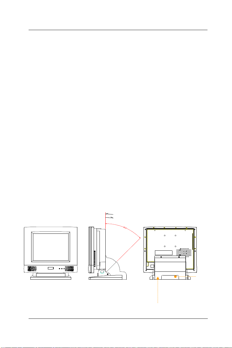
3.1.2. 45 to 900 Free Standing
The sleek and sturdy pedestal assembled with the two cable
management covers enables the APOLLO system to endure
the long-time operation in any public sectors. By swiveling
the knob on the left side of the base cover and pulling the
base up and down, the angle can be adjusted from 45 to 900.
FIGURE 3-1: APOLLO’S VERSATILE STANDING OPTIONS
Cable management cover
3-22
APOLLO 120/150 III
Cable
management
cutout
Page 33
User Manual version 2305
23
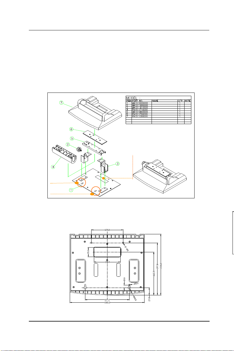
3.1.3. Fixed Standing
At the bottom side of the big pedestal, there are two
avocado-shape holes which are used to fix the APOLLO to the
table with screws. When the APOLLO is fixed to the table, the
angle from the main system to the table can be adjusted from
45 to 900 by swiveling the knob on the left side of the base
cover and pulling the base up and down.
Cable management cutout
Avocadoshape holes
FIGURE 3-2: APOLLO PEDESTAL KIT
The following figure illustrates the distance between the
avocado holes.
APOLLO °ò®y¼Ò²Õ
©³®yÅKªO
HINGE (¥ª) with LOCK
HINGE (¥k)
APOLLO 120/150 Âà¶b-×¹¢¤U»\
Âà¶b¤ä¬[
APOLLO 120/150 Âà¶b-×¹¢¤W»\
APOLLO 120/150 ¶ì½¦©³®y
FIGURE 3-3: APOLLO PEDESTAL BASE AVOCADO HOLES
APOLLO 120/150 III
3-
Page 34

User Manual version 2305
24
3.1.4. Cable Management
The APOLLO’s pedestal is not only a versatile stand but a
functional stand able to manage the system cabling.
1. The rectangle-shape opening (Fig. 3-2) at the bottom
side of the big pedestal can act as a cable management
cutout. All the cables connecting to the I/O ports can
come out from this opening, then down to the table.
2. The two base back covers (Fig. 3-1) can act as a set of
cable management covers. All the cables connecting to
the I/O ports come down in the covers, then out from this
opening at the rear side of the base.
3-
APOLLO 120/150 III
Page 35
25
User Manual version 2305
3.2. Wall Mounting and Mobile Applications
The APOLLO system provides 1 set of VESA mounting holes,
75*75mm on the rear side of the chassis. System integrators
can design their special wall mount brackets per the two sets
of VESA holes or obtain market-available swing arms for wall
mounting, table mounting or mobile applications.
FIGURE 3-4: APOLLO 120 VESA HOLES
APOLLO 120/150 III
3-
Page 36

User Manual version 2305
26
FIGURE 3-5: APOLLO 150 VESA HOLES
FIGURE 3-6 FIGURE 3-7
3-
APOLLO 120/150 III
Page 37

User Manual version 2305
27
3.3. Panel Mounting
The APOLLO system provides a set of optional mounting
brackets for system panel mounting. The following figures
illustrate the way to use the brackets for panel mounting.
FIGURE 3-8
APOLLO 120/150 III
FIGURE 3-9
3-
Page 38

User Manual version 2305
28
3.4. KIOSK Integration
The APOLLO system can also be integrated to a KIOSK
cabinet to make a ready-to-play KIOSK terminal. The
following is an example of APOLLO KIOSK. It is a flexible and
robust device that can be mounted virtually anywhere and in
any forms including tabletop, pedestal, pole and wall
mounting.
HERCULES T
HERCULES M
HERCULES K
3-
HERCULES P
HERCULES PK
APOLLO 120/150 III
Page 39

User Manual version 2305
4. I/O CONNECTION
This chapter describes the APOLLO
system I/O ports and how to use the I/O
interface to connect to external devices.
APOLLO 120/150 III
4-29
Page 40
User Manual version 2305
The I/O interfaces located at the rear side of the chassis are
used to connect external peripheral devices, such as a mouse,
a keyboard, a monitor, serial devices or parallel printer…etc.
Before any connection, make sure that the computer and the
peripheral devices are turned off.
4 2 1
FIGURE 4-1
4.1. Parallel Port
The APOLLO 120/150 can support the latest EPP and ECP
parallel port protocols. It can be used to connect to a wide
array of printers, ZIP drive, parallel scanner and any other
parallel devices. The printer interface on the APOLLO
120/150 III is a 25-pin female D-SUB connector. To connect
any parallel device, follow the steps below:
1. Turn off the system and the parallel devices.
2. Plug in the male connector of the parallel device to the
25-pin female D-SUB connector and fasten the retaining
screws.
3. Turn on the system and the attached parallel devices.
4. Refer to the parallel device’s manual for instruction to
configure the operation environment to recognize the new
attached devices.
5. You may need to run the CMOS setup to change the
hardware device setup.
4-30
APOLLO 120/150 III
Page 41

User Manual version 2305
4.2. COM Ports x 4
The APOLLO 120/150 features with four onboard COM ports.
COM 1, 2 & 4 are D-SUB serial ports located at the rear side
of the chassis, ready to connect to a wide range of serial
devices. COM 3 is internal serial port reserved for
touchscreen for internal connection. COM1, COM3 and COM4
are RS-232 and COM2 is RS-232/422/485, selected via
jumper setting. For COM 2 RS-232/422/485 selection,
please refer to SEC. 6.1.2.
COM 1, 2 & 4 are equipped with +5V/+12V power capabilities
on pin 9, providing easy accommodation to a broad range of
serial devices.
The COM port 5V/12 power is selected via jumper setting on
the IO board. The IO is the signal board attached to the rear
panel with 2 SCSI cables linking to the system motherboard
to connect the onboard signal out to the external I/O ports.
Please refer to SEC. 6.2.2 for 5V/12 power selection.
APOLLO 120/150 III
4-31
Page 42

User Manual version 2305
If a touchscreen module is installed, for factory default
setting, its controller will occupy COM3.
COM1, 2 & COM4 are all D-SUB 9-pin connectors. To connect
to any serial device; follow the procedures below;
1. Turn off the APOLLO system and the serial devices.
2. Attach the interface cable of the serial device to the 9-pin
D-SUB serial connector. Be sure to fasten the retaining
screws.
3. Turn on the computer and the attached serial devices.
4. Refer to the serial device’s manual for instruction to
configure the operation environment to recognize the new
attached devices.
5. If the serial device needs specified IRQ or address, you
may need to run the CMOS setup to change the hardware
device setup.
If the COM2 is to be set to RS-422/485 for long distance
transmission, the related onboard jumpers have to be set
correctly first. Refer to section 6.1.4.3 for the
RS-232/422/485 jumper settings.
4-32
APOLLO 120/150 III
Page 43
User Manual version 2305
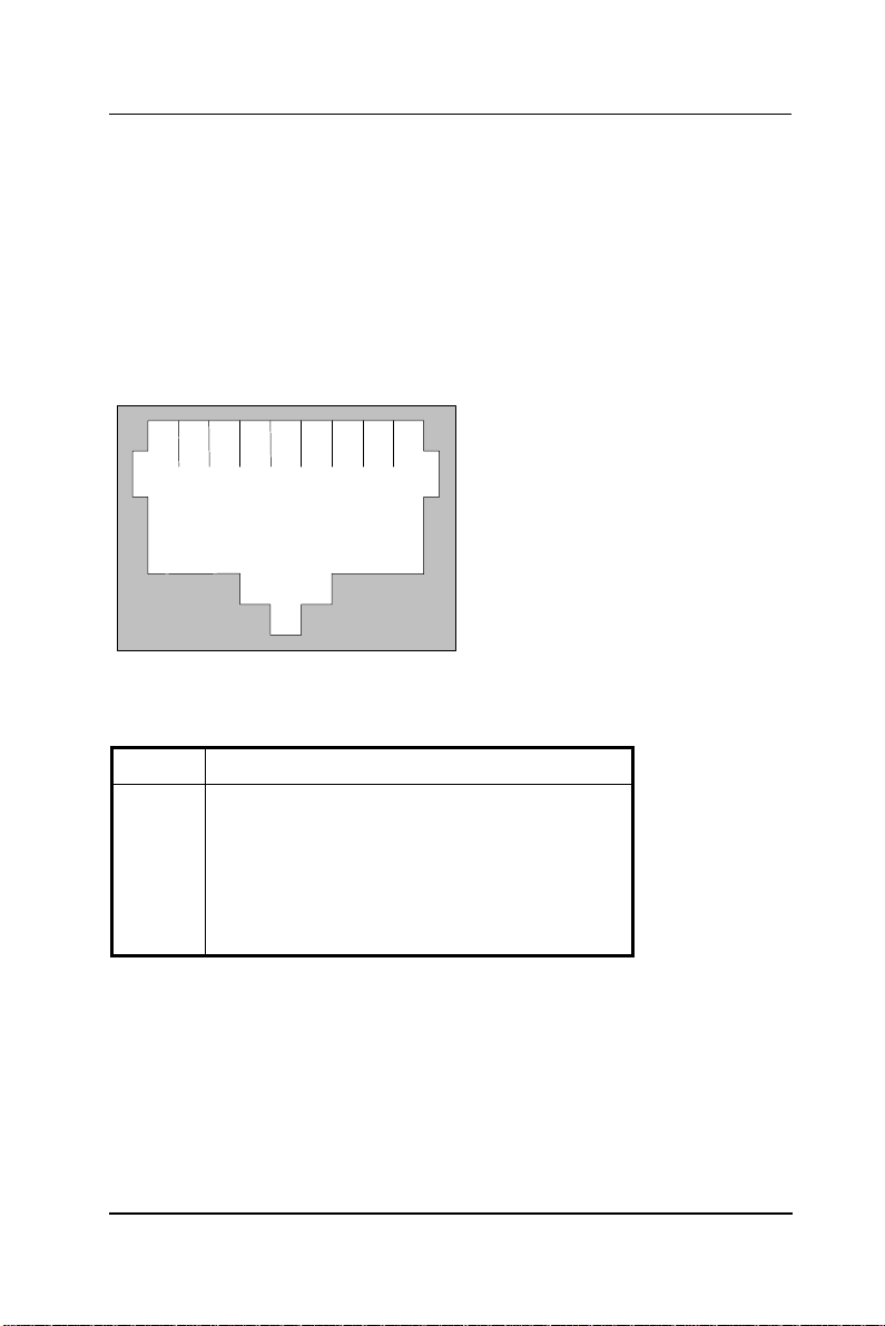
4.3. 100/10 Base-T Ethernet (RJ-45)
The APOLLO 120/150 provides a 100/10 Base-T NE2000
compatible Ethernet (RJ-45) interface. For network
connection, follow the instructions below.
1. Turn of the APOLLO system and the Ethernet hubs.
2. Plug in one end of cable of a 100/10 Base-T hub to the
system’s RJ-45 phone jack. The pin assignment of the
RJ-45 is listed as follow;
1
RJ-45 Connector Pin Assignment
Pin Description
1
2
3
6
others
2 3 4 5 6 7
RJ-45
Tx+ (data transmission positive)
Tx- (data transmission negative)
Rx+ (data reception positive)
Rx- (data reception negative)
No use
8
4.4. VGA Interface
The APOLLO 120/150 has a 15-pin analog RGB connector
located at the rear side of the chassis. It can support its own
LCD display and an expansion CRT or analog monitor at the
same time. The connection to an analog monitor is an easy
plug-in of the VGA D-SUB 15-pin connector to the RGB
interface.
APOLLO 120/150 III
4-33
Page 44

User Manual version 2305
34
4.5. 2nd Display Graphic Support Mode
The APOLLO can support SINGLE DISPLAY MODE and DUAL DISPLAY
MODE. For dual display mode, it can support MIRROR MODE
(same screen) or MULTIPLE-MONITOR MODE (different screens).
PLEASE NOTE THAT THE MULTIPLE-MONITOR MODE ONLY WORKS WHEN
THE OPERATING SYSTEM IS WINDOWS 98 OR WINDOWS ME OR
WINDOWS XP.
The APOLLO itself is onboard with an AGP LCD/VGA
controller. When dual display mode is activated, it can
support a LCD panel (digital TTL) and a CRT or an analog
monitor at either mirror mode or multiple-monitor mode.
The following sections describe all the graphic support modes
based on system memory clock frequency (66MHz, 100MHx
and 133MHz). All these tables apply only to video memory
size is equal or larger than 8MB.
4.5.1. When System Memory Clock = 66MHz
The following tables contain all graphic support modes under
the following condition and are classified under three output
modes (single mode, mirror mode and multiple-monitor
mode).
System memory clock = 66MHz
Memory bus width = 64 bit
Video memory size = 8MB or above
4-
APOLLO 120/150 III
Page 45

35
User Manual version 2305
4.5.1.1. Single Display Mode
Resolution Bpp
640*480 8 60, 72, 75, 85, 100, 120, 160, 200 60, 70, 75
16 60, 72, 75, 85, 100, 120, 160, 200 60, 70, 75
32 60, 72, 75, 85, 100, 120, 160 60, 70, 75
800*600 8 56, 60, 72, 75, 85, 100, 120, 160 60, 70, 75
16 56, 60, 72, 75, 85, 100, 120, 160 60, 70, 75
32 56, 60, 72, 75, 85, 100, 120 60, 70, 75
1024*768 8 43, 60, 70, 75, 85, 100, 120 60, 70, 75
16 43, 60, 70, 75, 85, 100, 120 60, 70, 75
32 43, 60, 70, 75
1280*1024 8 43, 60, 75, 85 60
16 43, 60, 75, 85
32 43
1600*1200 8 60, 65, 70, 75, 85
16 60
32
1920*1440 8 60
16
32
CRT1 LCD
APOLLO 120/150 III
4-
Page 46

User Manual version 2305
36
56, 60, 72, 75, 85, 100,
56, 60, 72, 75, 85, 100,
43, 60, 70, 75, 85, 100,
4.5.1.2. Mirror Display Output Mode
When LCD is selected as secondary display at mirror mode:
Resolution Bpp CRT1 at mirror mode LCD at mirror mode
640*480 8 60, 72, 75, 85, 100,
16 60, 72, 75, 85, 100,
32 60, 72, 75, 85, 100 60
800*600 8
16
32
1024*768 8
16
32
60, 70, 75
120, 160, 200
60, 70, 75
120, 160, 200
60, 70, 75
120, 160
60, 70, 75
120
60, 70, 75
120
4-
APOLLO 120/150 III
Page 47

37
4.5.1.3. Multiple Display Output Mode
56, 60, 72, 75, 85, 100,
56, 60, 72, 75, 85, 100,
43, 60, 70, 75, 85, 100,
When LCD is selected as secondary display at
multiple-monitor mode:
Resolution Bpp CRT1 at MM mode LCD at MM mode
640*480 8 60, 72, 75, 85, 100,
16 60, 72, 75, 85, 100,
32 60, 72, 75, 85, 100 60
800*600 8
16
32 56, 60
1024*768 8
16 43, 60, 70, 75
32 43
1280*1024 8 43, 60, 75, 85
16 43
32
1600*1200 8 60, 65
16
32
User Manual version 2305
60, 70, 75
120, 160, 200
60, 70, 75
120, 160, 200
60, 70, 75
120, 160
60, 70, 75
120
60, 70, 75
120
APOLLO 120/150 III
4-
Page 48

User Manual version 2305
38
4.5.2. When System Memory Clock = 100MHz
The following tables contain all graphic support modes under
the following condition and are classified under three output
modes (single mode, mirror mode and multiple-monitor
mode).
System memory clock = 100MHz
Memory bus width = 64 bit
Video memory size = 8MB or above
4.5.2.1. Single Display Mode
Resolution Bpp
640*480 8 60, 72, 75, 85, 100, 120, 160, 200 60, 70, 75
16 60, 72, 75, 85, 100, 120, 160, 200 60, 70, 75
32 60, 72, 75, 85, 100, 120, 160, 200 60, 70, 75
800*600 8 56, 60, 72, 75, 85, 100, 120, 160 60, 70, 75
16 56, 60, 72, 75, 85, 100, 120, 160 60, 70, 75
32 56, 60, 72, 75, 85, 100, 120, 160 60, 70, 75
1024*768 8 43, 60, 70, 75, 85, 100, 120 60, 70, 75
16 43, 60, 70, 75, 85, 100, 120 60, 70, 75
32 43, 60, 70, 75, 85, 100 60, 70, 75
1280*1024 8 43, 60, 75, 85 60
16 43, 60, 75, 85 60
32 43, 60
1600*1200 8 60, 65, 70, 75, 85
16 60, 65, 70, 75, 85
32
1920*1440 8 60
16 60
32
CRT1 LCD
4-
APOLLO 120/150 III
Page 49

39
4.5.2.2. Mirror Display Output Mode
56, 60, 72, 75, 85, 100,
56, 60, 72, 75, 85, 100,
43, 60, 70, 75, 85, 100,
43, 60, 70, 75, 85, 100,
When LCD is selected as secondary display at mirror mode:
Resolution Bpp CRT1 at mirror mode LCD at mirror mode
640*480 8 60, 72, 75, 85, 100,
16 60, 72, 75, 85, 100,
32 60, 72, 75, 85, 100,
800*600 8
16
32 56, 60, 72, 75, 85 60
1024*768 8
16
32
User Manual version 2305
60, 70, 75
120, 160, 200
60, 70, 75
120, 160, 200
60, 70, 75
120, 160
60, 70, 75
120, 160
60, 70, 75
120, 160
60, 70, 75
120
60, 70, 75
120
APOLLO 120/150 III
4-
Page 50

User Manual version 2305
40
56, 60, 72, 75, 85, 100,
56, 60, 72, 75, 85, 100,
43, 60, 70, 75, 85, 100,
43, 60, 70, 75, 85, 100,
4.5.2.3. Multiple Display Output Mode
When LCD is selected as secondary display at
multiple-monitor mode:
Resolution Bpp CRT1 at MM mode LCD at MM mode
640*480 8 60, 72, 75, 85, 100,
16 60, 72, 75, 85, 100,
32 60, 72, 75, 85, 100,
800*600 8
16
32 56, 60, 72, 75, 85 60
1024*768 8
16
32 43, 60
1280*1024 8 43, 60, 75, 85
16 43, 60, 75
32
1600*1200 8 60, 65, 70, 75, 85
16
32
1920*1440 8 60
16
32
60, 70, 75
120, 160, 200
60, 70, 75
120, 160, 200
60,70, 75
120, 160
60, 70, 75
120, 160
60, 70, 75
120, 160
60, 70, 75
120
60, 70, 75
120
4-
APOLLO 120/150 III
Page 51

User Manual version 2305
41
4.5.3. When System Memory Clock = 133MHz
The following tables contain all graphic support modes under
the following condition and are classified under three output
modes (single mode, mirror mode and multiple-monitor
mode).
System memory clock = 133MHz
Memory bus width = 64 bit
Video memory size = 8MB or above
APOLLO 120/150 III
4-
Page 52

42
User Manual version 2305
4.5.3.1. Single Display Mode
Resolution Bpp
640*480 8 60, 72, 75, 85,
16 60, 72, 75, 85,
32 60, 72, 75, 85,
800*600 8 56, 60, 72, 75,
16 56, 60, 72, 75,
32 56, 60, 72, 75,
1024*768 8 43, 60, 70, 75,
16 43, 60, 70, 75,
32 43, 60, 70, 75,
1280*1024 8 43, 60, 75, 85 60
16 43, 60, 75, 85 60
32 43, 60, 75, 85 60
1600*1200 8 60, 65, 70, 75,
16 60, 65, 70, 75,
32 60
1920*1440 8 60
16 60
32
CRT1 LCD
60, 70, 75
100, 120, 160,
200
60, 70, 75
100, 120, 160,
200
60, 70, 75
100, 120, 160,
200
60, 70, 75
85, 100, 120,
160
60, 70, 75
85, 100, 120,
160
60, 70, 75
85, 100, 120,
160
60, 70, 75
85, 100, 120
60, 70, 75
85, 100, 120
60, 70, 75
85, 100, 120
85
85
4-
APOLLO 120/150 III
Page 53

43
4.5.3.2. Mirror Display Output Mode
56, 60, 72, 75, 85, 100,
56, 60, 72, 75, 85, 100,
56, 60, 72, 75, 85, 100,
43, 60, 70, 75, 85, 100,
43, 60, 70, 75, 85, 100,
When LCD is selected as secondary display at mirror mode:
Resolution Bpp CRT1 at mirror mode LCD at mirror mode
640*480 8 60, 72, 75, 85, 100,
16 60, 72, 75, 85, 100,
32 60, 72, 75, 85, 100,
800*600 8
16
32
1024*768 8
16
32
User Manual version 2305
60, 70, 75
120, 160, 200
60, 70, 75
120, 160, 200
60, 70, 75
120, 160, 200
60, 70, 75
120, 160
60, 70, 75
120, 160
60, 70, 75
120
60, 70, 75
120
60, 70, 75
120
APOLLO 120/150 III
4-
Page 54

User Manual version 2305
44
56, 60, 72, 75, 85, 100,
56, 60, 72, 75, 85, 100,
56, 60, 72, 75, 85, 100,
43, 60, 70, 75, 85, 100,
43, 60, 70, 75, 85, 100,
4.5.3.3. Multiple Display Output Mode
When LCD is selected as secondary display at
multiple-monitor mode:
Resolution Bpp CRT1 at MM mode LCD at MM mode
640*480 8 60, 72, 75, 85, 100,
16 60, 72, 75, 85, 100,
32 60, 72, 75, 85, 100,
800*600 8
16
32
1024*768 8
16
32 43, 60, 70, 75
1280*1024 8 43, 60, 75, 85
16 43, 60, 75, 85
32 43
1600*1200 8 60, 65, 70, 75, 85
16 60, 65
32
1920*1440 8 60
16
32
60, 70, 75
120, 160, 200
60, 70, 75
120, 160, 200
60,70, 75
120, 160, 200
60, 70, 75
120, 160
60, 70, 75
120, 160
60, 70, 75
120
60, 70, 75
120
60, 70, 75
120
4-
APOLLO 120/150 III
Page 55

User Manual version 2305
45
4.6. PS/2 Keyboard Interface
The APOLLO provides a standard PS/2 keyboard connector
located at the rear panel. If the user would like to use AT
keyboard, then an adapter to connect the PS/2 KB to AT KB is
needed.
4.7. PS/2 Mouse Interface
The APOLLO system has one PS/2 mouse connector located
at the rear side. A simple plug-in will make the connection.
APOLLO 120/150 III
4-
Page 56

User Manual version 2305
46
1
2
3
4
5
6
7
8
9
1
0
out connector when an external floppy
4.8. External FDD (DB-15)
The APOLLO 120/150 provides two ways to connect to a
floppy disk drive to fit into specific environmental
applications:
1. Internal FDD
2. External FDD
If the FDD is frequently used, it is suggested to use an
internal floppy disk drive. If the drive is used only for system
installation or maintenance, then, an external device can
fulfill this need and is more economical. Please note that if an
internal floppy disk drive already exists, no external floppy
drive can be used.
The APOLLO external FDD interface is a 15-pin D-sub
connector located at the rear side of the chassis. An external
FDD cable is provided to connect a standard 3.5” FDD to the
system. Its pin position and pin assignment are listed as
follows.
Pin # Signal Pin #
1 DELSEL
2 -INDEX
3 -MTR1
4 -DVR1
5 -DIR 13 -DSKCHG
6 -WP 14 +5V
7 -TRKO
8 -WG
The APOLLO system is equipped with a
+5V/12V DC-out connector to provide 5V
power to drive the external floppy disk
drive. Use the provided FDD power cable
to connect the floppy drive to the 5V
DCdrive is attached to the system.
4-
9 -WD
10 -STEP
11 -RD
12 -HDSEL
15 +12V
Signal
11
12
13
14
15
APOLLO 120/150 III
Page 57

User Manual version 2305
47
4.9. +5V/12V DC-Out
The APOLLO system provides a +5V/12V DC-out connector.
It is used to provide necessary power source for some
external devices. For example, if the APOLLO III system is to
be housed in a KIOSK cabinet which requests extra cooling
fan for heat dispensing, then the fan power cable can be
attached to 5V/12V DC-out to obtain power from the
computer directly. If an external floppy disk drive is attached
to the system, it will need +5V power source from the system.
A power cable for the external floppy disk drive is already
provided for this connection. For other devices, you might
need to make your own power cable for the connection.
4.10. VR Brightness Control
The APOLLO system provides a VR control to adjust the
brightness of the LCD. The VR control is with a “+” shape
cutout on it. You will need a “+” shape screwdriver to adjust
it for display brightness control.
APOLLO 120/150 III
4-
Page 58
User Manual version 2305
48
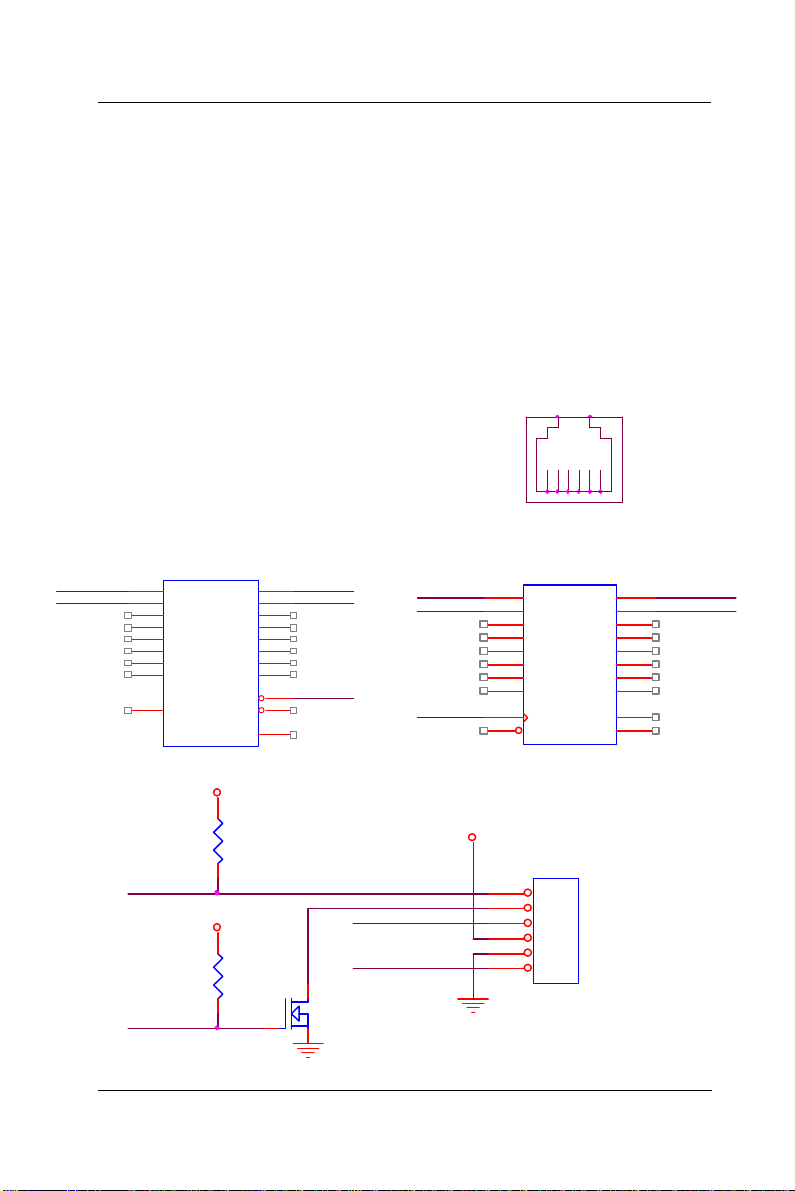
4.11. DIO (Digital Input & Output)
The APOLLO III provides 2-channel digital input and output
that can be used for the system’s simple automation control
needs. The digital I/O can be configured to control the
opening of a cash drawer or to sense the warning signal of an
uninterrupted power system (UPS) or to do the store security
control.
The DIO port address and pin definition is listed below;
I/O Port address: 208H
Read: SD0, SD1
Write: SD4, SD5
IO 208H(READ)
IO 206H(READ)
74LS244
VCC5
1A11Y1
1A21Y2
1A31Y3
1A41Y4
2A12Y1
2A22Y2
2A32Y3
2A42Y4
GND
218
416
614
812
119
137
155
173
-IOR206H
1
1G
1920
2GVDD
10
SD0 IN_0
SD1 IN_1
OUT_0
4.7K
VCC5
OUT_1
4.7K
IN_0
IN_1
MOSFET N
SD4
SD5
-IOW206H
VCC12
DIO1
RJ11
1 2 3 4 5 6
IO 208H(WRITE)
IO 206H(WRITE)
13
14
17
18
11
3
4
7
8
1
D1
D2
D3
D4
D5
D6
D7
D8
CLK
CLR
74LS273
1
2
3
4
5
6
VCC
GND
Q1
Q2
Q3
Q4
Q5
Q6
Q7
Q8
DIO1
RJ11
2
5
6
9
12
15
16
19
20
10
OUT_0
OUT_1
4-
APOLLO 120/150 III
Page 59

User Manual version 2305
49
The Digital I/O is of TTL interface. It is controlled via
software programming.
Digital I/O Programming
Input/output address: 208H
In_Data 0~3=SD0~SD1
Out_Data 0~3 SD4~SD7
EXAMPLE:
10 REM Digital I/O example program
20 X = INP (&H208) REM INPUT Digital I/O port
for 4 bit
30 X = OUT (&H208) REM OUTPUT Digital I/O port
for 4 bit
60 END
100 Return
Port 208H Definition
APOLLO 120/150 III
4-
Page 60

User Manual version 2305
50
4.12. Audio Interface (Line-in, MIC-in, SPK-out)
The audio interface contains three jacks, microphone-in,
line-in and speaker-out.
The microphone-in jack is used to record sound or voice by
connecting to an external microphone. The line-in jack is
used to input audio from an external audio device such as a
CD player, tape recorder or a radio. The speaker-out jack is
to output the audio to external devices such as speakers or
earphones. The audio device can be directly attached to the
jacks. Please note that the audio driver has to be installed
first before using any audio device.
4.13. USB Ports
The APOLLO 120/150 III also provides two USB ports to
connect to external USB devices. A simple plug-in of the USB
device interface cable to the USB port will make the
connection. Before using the USB devices, remember to
install the device driver first.
4.14. IR Keyboard Sensor (optional)
The APOLLO III features with an optional IR keyboard sensor.
The IR KB sensor containing wireless KB firmware is located
at the front bezel. To use the wireless keyboard, please note
that the APOLLO III IrKB sensor on the front bezel and the
wireless keyboard sensor have to face each other at the same
horizontal level and the distance of the IR transceiver and
receiver should not exceed 1 meter.
4.15. AC/DC Inlet/Power Switch
For APOLLO 120/150 III AC system, it can operate in the
input range from 100 ~ 240 volts, 50 ~ 60 Hz. For DC system,
the input range can be from 18V to 72V with different power
supply.
4-
APOLLO 120/150 III
Page 61

User Manual version 2305
51
5. HARDWARE INSTALLATION AND UPGRADE
This chapter overviews the installation of the
APOLLO III’s internal components and devices.
This chapter is for service engineers not for the
end user. Sections include:
u The exploded diagram
u Motherboard assembly
u Touchscreen controller
u LCD module assembly
u Front Bezel assembly
u HDD module assembly
u CD-ROM/FDD assembly
u Power module assembly
u Expansion slots
u Stand assembly
APOLLO 120/150 III
5-
Page 62

User Manual version 2305
52
The APOLLO 120/150 III consists of a Celeron/ Pentium® III
multimedia motherboard with an adequate CPU and relevant
SDRAM on it. The system control board and other internal
devices such as expansion card, HDD and power supply are
already housed in a plastic rear cover. The system’s
performance depends on the installed CPU and the capacity
of the system memory and hard disk drive. In some
circumstances, you might intend to upgrade or maintain the
system. By removing the rear cover and the metal covers,
the internal components such as CPU, SDRAM, HDD, internal
FDD, CD-ROM and power supply can be easily accessed for
maintenance and upgrade.
The APOLLO is composed of 10 major modules. The
installation procedure is also listed as below.
1. Motherboard module
2. Touchscreen controller module
3. HDD module
4. LCD module
5. Front bezel module
6. CD-ROM/FDD module
7. Power supply module
8. Expansion slot module
9. Back panel module
10. Stand module
To disassemble the system module for maintenance, the
procedure is from step 10 to 1.
5-
APOLLO 120/150 III
Page 63
User Manual version 2305
53
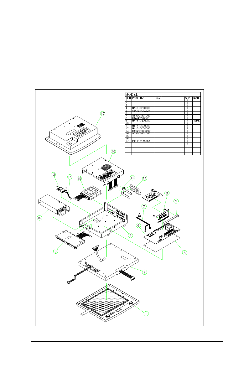
XPLODED DIAGRAM
5.1. Recognizing the System Major Parts
In terms of LCD size, the APOLLO has two models, one 12.1”
and the other 15.1”. The assembly of the two models is
basically the same except the LCD assembly. The following
diagram highlights the system major parts that make up the
APOLLO 120 main system.
FIGURE 5-1: APOLLO 120 E
APOLLO 120 ¥DÅé²Õ«~
APOLLO 120 -±ªO²Õ«~
APOLLO 120 LCD²Õ«~
CDROM-FDD²Õ«~
½cÅé
¥D¾÷ªOµ´½t¤ù302*148*0.35
PC620 ¼Ò²Õ A1.0
POWER CABLE ¤j4P-¤p4P*2-2P 180mm
MODULE APOLLO RISER A1.0
RISER CARD¸É±j±ì
POWER ²Õ«~
«áµ¡
µL¤ÕÅK¤ù
MODULE M2210 A1.0
TOUCH COM3 CABLE 80mm
HDD ²Õ«~
ÅK¥ó«á»\²Õ«~
APOLLO 120¶ì½¦«á»\
APOLLO 120/150 III
5-
Page 64
User Manual version 2305
54
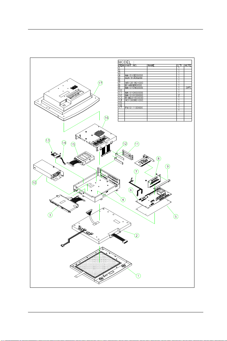
The following diagram shows the system major parts that
make up the APOLLO 150 main system.
APOLLO 150 ¥DÅé²Õ«~
APOLLO 150 -±ªO²Õ«~
APOLLO 150 LCD²Õ«~
CDROM-FDD²Õ«~
½cÅé
¥D¾÷ªOµ´½t¤ù302*148*0.35
PC620 ¼Ò²Õ A1.0
POWER CABLE ¤j4P-¤p4P*2-2P 180mm
MODULE APOLLO RISER A1.0
RISER CARD¸É±j±ì
POWER ²Õ«~
«áµ¡
µL¤ÕÅK¤ù
MODULE M2210 A1.0
TOUCH COM3 CABLE 80mm
HDD ²Õ«~
ÅK¥ó«á»\²Õ«~
APOLLO 150¶ì½¦«á»\
5-
FIGURE 5-2: APOLLO 150 EXPLODED DIAGRAM
APOLLO 120/150 III
Page 65

User Manual version 2305
55
5.2. Installing the CPU
The APOLLO III can adapt Socket 370 Intel Celeron or
Pentium III CPU. Upgrading the CPU can increase the system
performance. When Pentium III 1GB 133MHz is used with
the system, it is suggested to attach another system cooling
fan at the right side of the system compartment to prevent
the system from overheating.
The APOLLO’s motherboard provides one 370-pin ZIF socket
(Socket 370). The CPU must come with a CPU fan with a heat
sink on to avoid overheating.
To install a CPU or upgrade a new CPU, follow the instructions
below.
1. If there is an existing CPU on the socket, remove the CPU
cooling fan first. Then remove the CPU by pulling the
lever out a little and raising it, then lifting out the existing
CPU from the socket.
2. To insert the CPU into the socket, the notch on the corner
of the CPU (the corner with golden dot) should point
toward the end of the socket lever. If the insertion of the
CPU to the socket is not easy, check whether the CPU pins
correspond with the holes on the socket.
3. After insert the CPU into the socket, pull the lever down to
make sure the CPU is in place.
4. The CPU cooling fan comes with a 3-pin power cable.
Connect the power cable to the 3-pin power connector,
FAN1 on the motherboard.
5. There are two white clips on the CPU socket. Make sure
the cooling CPU fan clips click into place.
3-pin CPU fan power connector
CPU socket
APOLLO 120/150 III
FIGURE 5-3
5-
Page 66

User Manual version 2305
56
5.3. Installing the SDRAM Memory Module
The APOLLO 120/150 III system control board provides 1 x
168-pin DIMM socket, able to support SDRAM memory from
32MB up to 512MB. To install the memory module, follow the
instructions below.
1. Find the 168 pin DIMM socket on the motherboard
2. There are two white eject levers at each end of the DIMM
socket. Push them outward until they separate from the
two vertical posts.
3. Holding the memory module with the notch on the upper
right corner, then insert the memory module into the
DIMM socket at 90° angle.
4. Push the two eject levers toward the vertical posts until
they click into place. The memory module is now
upright.
The system is able to auto detect the new memory size and
there is no need to change the system configuration after
installation.
Make sure that the memory module you are using can handle
the specified SDRAM MHz. Inadequate memory module will
make the computer unable to boot up.
5-
APOLLO 120/150 III
Page 67

User Manual version 2305
57
5.4. Motherboard Assembly
The motherboard is the first component to be assembled to
the system compartment. Follow the steps below to
assemble the motherboard to the system chassis. Make sure
the CPU with cooling fan and SDRAM are already properly
installed to the motherboard before the motherboard is
attached to the system chassis. (Refer to Sec. 5-2 and 5-3 for
CPU and SDRAM installation).
1. The lower side of the chassis has a rectangle opening at
the bottom of the chassis. Make the lower side of the
chassis to be near you.
2. From your point of view, the motherboard module is to be
installed to the lower side of the system compartment.
3. Tape the motherboard insulator (5) (Fig. 5-1 & 5-2 (5)) to
the motherboard (6) first. The insulator is to separate the
electronic components on the reverse side of the
motherboard from the metal compartment to prevent
short circuitry caused during system operation.
4. Fix the motherboard (6) to the chassis with 7 PMS
anti-fallen 3*6 screws.
5. The IR/LED 2*13-pin cable (Fig. 5-7 (7) & Fig. 5-8 (5)) has
to go through the rectangle opening located at the bottom
side of the chassis, then connected to motherboard’s J9,
the HDD LED & ACPI LED & SMI connector.
APOLLO 120/150 III
5-
Page 68

User Manual version 2305
8
5.5. Touch Controller Assembly
If a touchscreen is integrated with the system, the
touchscreen controller is to be installed right after the
installation of the motherboard.
For easy maintenance in the future, the controller is to be
installed to a bracket rather than to the system compartment
directly. From your point of view, there is a rectangle opening
at the left upper side of the chassis. Insert the touch
controller bracket to the opening and retain it to the chassis
with 2 FMS 3*5 screws.
For easy assembly, the related cables are to be connected
first.
1. For Elo touch, the touchscreen cable (Fig. 5-1. (14)) is a
2*5-pin to 2*5-pin flat cable. One end is connected to the
touchscreen controller first.
2. There is a 2-pin (black & red) cable to provide the power
source for the touchscreen. Connect one end to the
controller.
3. Connect the other end of the 2*5-pin to 2*5-pin flat cable
to the onboard COM 3 box header connector and connect
the other end of the 2-pin power cable to the
motherboard’s PWR1.
4. Fix the touchscreen controller (13) to the bracket with 2
PMS 3*6 screws.
5. Fold both cables properly.
6. Make sure the two screws at the outward upper side of the
chassis are also properly fixed.
5-5
APOLLO 120/150 III
Page 69

User Manual version 2305
59
5.6. HDD Module Assembly
The APOLLO provides enough space to build in a 3.5” hard
disk drive in the system compartment. The following steps
show the way to install an internal hard disk drive.
1. Make the chassis lower side near you. Now, from your
point of view, the 3.5" HDD module is to be installed to the
right upper side of the system compartment.
2. Refer to Figure 5-4. Fix the hard disk drive (1) to the HDD
bracket (3) with one FTS 3*5 screw.
3. Connect the one end of the 40-pin IDE cable (2) to hard
disk drive.
4. There are two clips at the bottom of the compartment used
to hold the HDD module to the system compartment.
Insert the HDD module to the compartment and clip it into
place. Fix the HDD module to the chassis with one 3*5
FMS screw outside of the right upper side of the chassis.
5. Make sure the other end of the 40-pin IDE cable is
connected to the motherboard IDE 1 connector.
HDD ²Õ«~
HDD
HDD CABLE 220mm
HDD ¬[
FIGURE 5-4: HDD INSTALLATION
APOLLO 120/150 III
5-
Page 70
User Manual version 2305
60
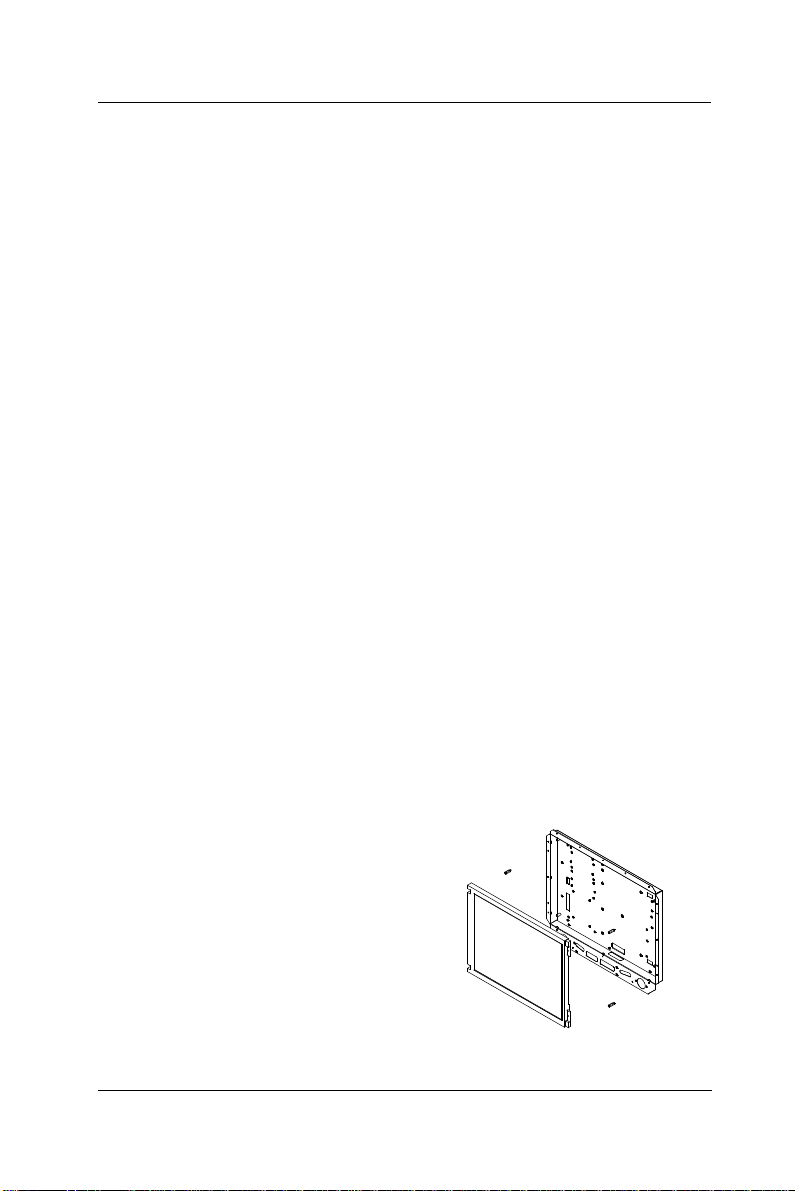
5.7. Touchscreen or Front Bezel Assembly
The APOLLO is able to accommodate Elo analog resistive
touch or Intelli (SAW) touch or MicroTocu capacitive
touchscreen. PLEASE NOTE THAT WHEN DIFFERENT TOUCH MODULE IS
INSTALLED, DIFFERENT TOUCHSCREEN METAL BRACKETS ARE NEEDED.
YOU CAN NOT REPLACE ONE TYPE OF TOUCH PANEL WITH THE OTHER
WITHOUT CHANGING THE TOUCHSCREEN METAL BRACKETS USED TO HOLD
THE TOUCH PANEL TO THE FRONT BEZEL.
The following steps illustrate the ways to assemble the
toucshcreen to the front bezel.
1. There are 4 rubber slips with one-side taped with glue.
Glue the 4 slips to the gutters located at the reverse side
of the plastic front bezel. The 4 rubber slips act as
cushions to absorb the pressure when the touchscreen is
fixed to the front bezel with screws.
2. There are 4 metal brackets used to fix the touchscreen to
the front bezel. The metal brackets have to be taped with
soft tapes as shown on Figure 5-6 (7) & (8).
3. Then, fix the touchscreen to the front bezel with the 4
metal brackets with screws. The soft tapes are used to
absorb the pressure when the metal brackets fix the
touchscreen to the front bezel.
If no toushcreen is installed, there are two options. One is to
put a resilient glass instead. The advantage of putting a
resilient glass is to protect the LCD panel.
The other option is to fix 4
bronze sticks (5 mm) to the
LCD bracket to push the LCD
panel forward to make up the
gap between the LCD and the
front bezel. But when using
this way, two screw holes on
the front bezel need to be cut
to prevent LCD mechanism
interference to the front bezel.
FIGURE 5-5: APOLLO W/O TOUCH
5-
APOLLO 120/150 III
Page 71
User Manual version 2305
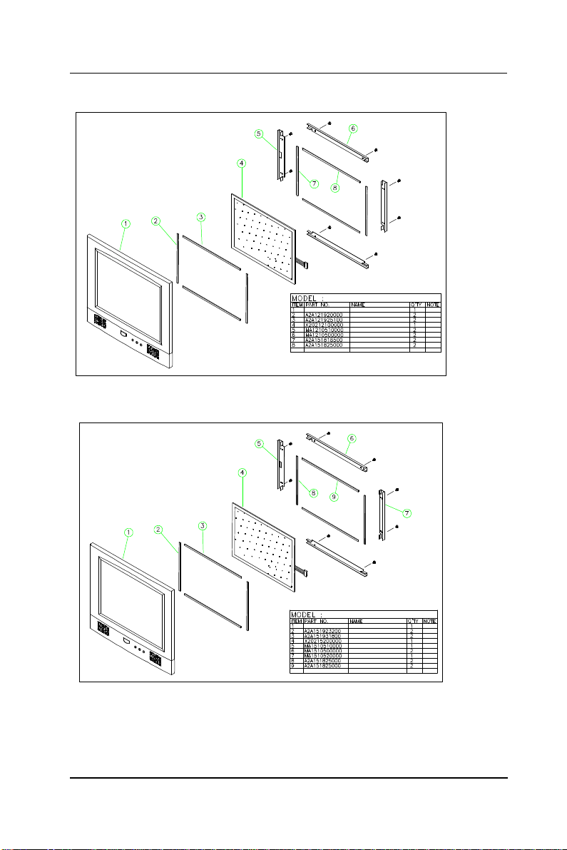
61
APOLLO 120 -±ªO²Õ«~
12" -±ªO²Õ¥ó
12" ¾ó½¦À£±ø(¥ª¥k)
12" ¾ó½¦À£±ø(¤W¤U)
12.1"ELO TOUCH ¹qªý¦¡
ELO 12.1"À£±ø(¥ª¥k)
ELO 12.1"À£±ø(¤W¤U)
ªw´ÖÀ£±ø 185*5*1 mm ¥ª¥kPE
ªw´ÖÀ£±ø 250*5*1 mm ¤W¤UPE
FIGURE 5-6: APOLLO 120 FRONT BEZEL ASSEMBLY
FIGURE 5-7: APOLLO 120 FRONT BEZEL ASSEMBLY
APOLLO 150 -±ªO²Õ«~
15" -±ªO²Õ¥ó
15" ¾ó½¦À£±ø232*5*2(¥ª¥k)
15" ¾ó½¦À£±ø318*5*2(¤W¤U)
15.0"ELO TOUCH ¹qªý¦¡
ELO 15.0"À£±ø(¥ª)
ELO 15.0"À£±ø(¤W¤U)
ELO 15.0"À£±ø(¥k)
ªw´ÖÀ£±ø 185*5*1 mm ¥ª¥kPE
ªw´ÖÀ£±ø 250*5*1 mm ¤W¤UPE
APOLLO 120/150 III
5-
Page 72

User Manual version 2305
62
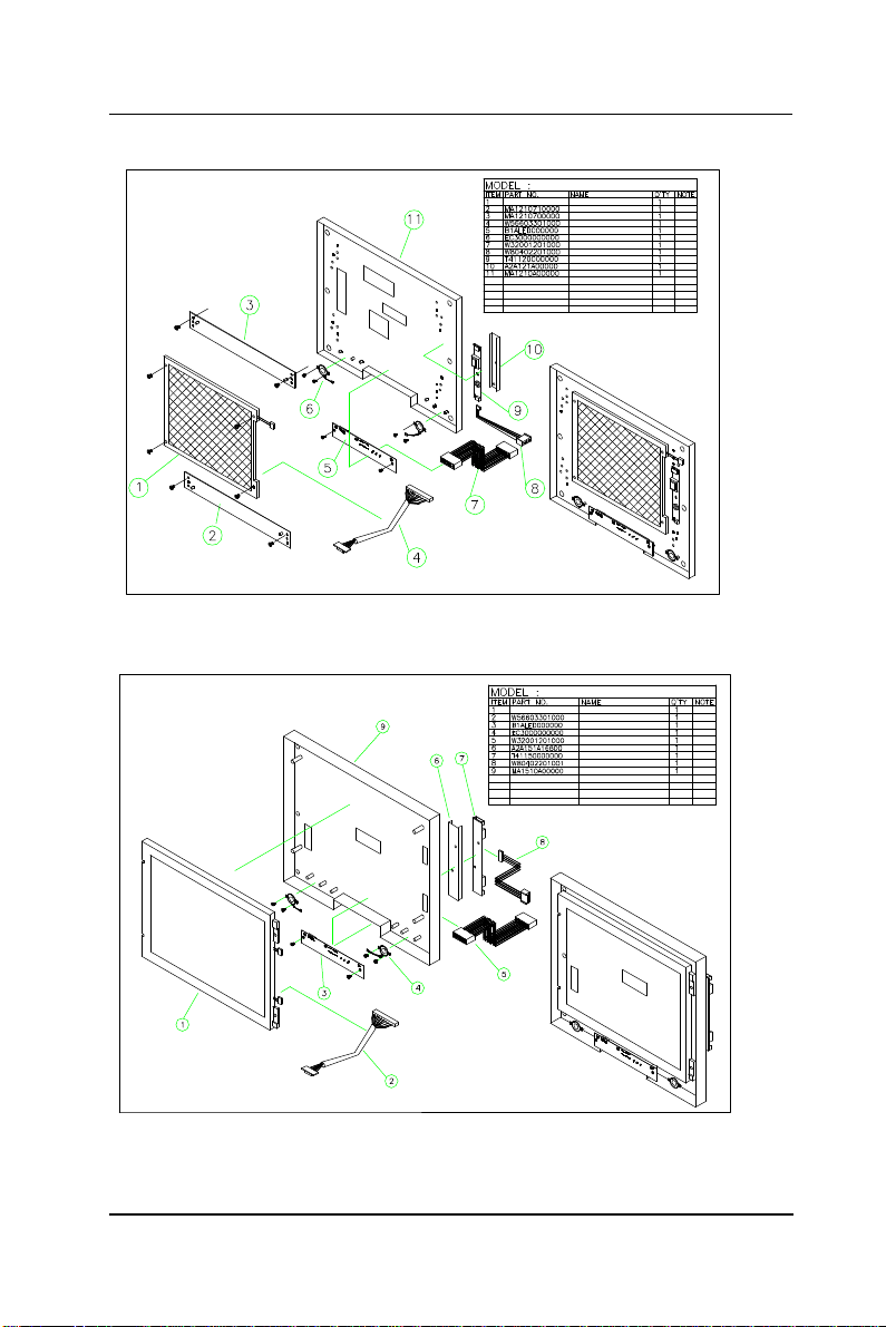
5.8. LCD Module Assembly
Figure 5-8 and 5-9 illustrate the way to assemble the
APOLLO’s LCD module.
The LCD does not fix to the main system directly. Rather, it is
to be fixed to a LCD holder, then to the main system. The
assembly of APOLLO 120 LCD module slightly differs from
that of APOLLO 150.
APOLLO 120
1. Refer to Figure 5-8. There are two LCD brackets (2) & (3)
used to fix to the LCD panel (1) to the LCD holder (11)
from the up & down sides.
2. Fix the LCD panel to the LCD holder with four PMS 3*8
screws.
3. The standard LCD used in APOLLO 120 is SANYO
MXS121022010 or its equivalent. It is a TTL interface
LCD. The LCD cable (4) is a DF9-41S to 2*25-pin cable
with around 35 cm in its length. Insert the 41-pin end
into the opening at the rear side of the LCD holder and
have it firmly plugged to the 41-pin connector at the rear
side of the LCD panel.
4. Attach the insulator (10) to the invertor (9).
5. The invertor cable (8) is a 4-pin to 4-pin cable with wafer
connectors at both sides. Connect the one end to
invertor first. The other end is for later connection to the
INV1 on the motherboard.
6. Connect the pink-white high voltage wires from the LCD
to the invertor.
7. The invertor module is to be fixed at the right middle
side of the LCD holder with the up side down.
8. For APOLLO 120, the IR/LED board (2) is to be fixed to
the lower side of the LCD holder.
9. The two speakers are to be fixed to the right and left
sides of the IR/LED board. The speaker wires are to be
connected to the 2-pin header on the IR/LED board.
5-
APOLLO 120/150 III
Page 73

User Manual version 2305
63
APOLLO 150
1. Refer to Figure 5-9. The standard LCD used in APOLLO
150 is either 15.1” TTL LG 151X2 or 15” LVDS Chi Mei
M150X3-L01 or their equivalent. The assembly of TTL
LCD differs from that of the LVDS LCD.
2. Fix the LCD panel (1) to the LCD holder (9) with four
PMS 3*8 screws.
3. For the TTL LCD, LM151X2 or its equivalent, the LCD
cable (2) is a DF9-41S to 2*25-pin cable with around 35
cm in its length. Insert the 41-pin end into the opening
at the rear side of the LCD holder and have it firmly
plugged to the 41-pin connector at the rear side of the
LCD panel. The other end is for later connection to the
LCD1 on the motherboard.
4. For the LVDS LCD, M150X3-L01 or its equivalent, as the
motherboard’s display is a TTL controller, to connect the
onboard LCD controller to the LVDS LCD, an LVDS
transceiver board is needed.
5. The APOLLO 150’s LVDS transceiver board is to be fixed
at the system chassis between the touch controller and
HDD.
6. The LCD cable for the LVDS LCD is a DF14-20 to
DF14-20 cable with around 35 cm in its length. Connect
one end to the connector located at the rear side of the
LCD panel with the other end going through the opening
at the rear side of the LCD holder for later connection to
the LVDS1 on the LVDS board.
7. There is a 2*25-pin to 2*25-pin LVDS cable. Plug one
end to the LCD1 on the LVDS board with the other end
connected to the 2*25-pin header connector, LCD1 on
the motherboard.
8. Attach the insulator (6) to the invertor (7).
9. The invertor cable (8) for APOLLO 150 is a 7-pin to 4-pin
cable with wafer connectors at both sides. Connect the
7-pin end to the invertor first. The other end is for later
connection to the INV1 on the motherboard.
APOLLO 120/150 III
5-
Page 74

User Manual version 2305
64
10. Connect the pink-white high voltage wires from the LCD
to the invertor.
11. The invertor module is to be fixed at the reverse side of
the LCD holder after the LCD module is to be installed to
the system.
12. For APOLLO 150, fix 6 bronze sticks (15 mm) to the
lower sides of the LCD holder. Fix the IR/LED board to
the LCD holder with two 3*6 screws.
13. The two speakers (Fig. 5-8 (6)) are to be fixed to the
right and left sides of the IR/LED board. The speaker
wires are to be connected to the 2-pin header on the
IR/LED board.
5-
APOLLO 120/150 III
Page 75
User Manual version 2305
65
12" LCD ²Õ«~
12.1"LCD PANEL
12"LCD©T©w¬[¤U
12"LCD ©T©w¬[¤W
LCD CABLE DFP41-50P 330mm
MODULE APOLLO LED A1.0
SPEAKER
LED CABLE 120mm
12"INVERTER MOLEX P-HRS4P 220mm
INVERTER 12.1"TORISAN
12"INVERTERµ´½t¤ù120*26.7*0.35
12"«eÅKªO
FIGURE 5-8: APOLLO 120 LCD MODULE ASSEMBLY
15" LCD ²Õ«~
15.0" LCD PANEL
LCD CABLE DFP41-50P 330mm
MODULE APOLLO LED A1.0
SPEAKER
LED CABLE 120mm
15"µ´½t¤ù168*39*0.35
INVERTER 15"
15" INVERTER MOLEX 4P-JAE7P 220mm
15"«eÅKªO
FIGURE 5-9: APOLLO 150 LCD MODULE ASSEMBLY
APOLLO 120/150 III
5-
Page 76

User Manual version 2305
66
After finishing the LCD module installation, the module is to
be assembled to the front bezel module, then to the chassis
with the motherboard and touch controller already on.
1. Use special air blower to blow any dust between the LCD
and touchscreen before the two modules are assembled
together. Retain the LCD module and the front bezel
module together with 8 FMS 3*6 screws.
2. Install the whole front bezel module with LCD already on
to the system chassis with the motherboard, touchscreen
controller and HDD module already on.
3. The LCD cable is already at the rear side of the LCD holder
through the cutout. Make sure the other end is to go
through the rectangle opening at the rear side of the
system chassis and have it connected to LCD connector,
LCD1 on the motherboard.
SPECIAL ATTENTION NEEDS TO BE PAID WHEN PLUGGING THE LVDS OR
LCD CABLE TO THE LCD HEADER CONNECTOR ON THE MOTHERBOARD.
MAKE SURE PIN 1 OF THE ONBOARD LCD CONNECTOR MATCH PIN 1 OF
THE CABLE. ANY WRONG PLUGGING OR SHIFTED PLUGGING WILL
DAMAGE THE LCD PANEL OR LEAD TO MAL-FUNCTION.
4. The touchscreen 5-pin flat cable should go through the
rectangle opening at the left side of the LCD holder, then
get into the chassis from the oval-shape cutout at the left
side of the chassis. Connect this cable to the touchcreen
controller. Connect the other end of the touch power cable
to the onboard PWR 1.
5. For APOLLO 150, the invertor now is to be fixed to the left
outward side of the chassis and have the invertor cable go
into the chassis through the cutout. Connect the other
end of the invertor cable to the motherboard’s INV1.
6. Connect the other end of the IR/LED cable to the IR/LED
board.
5-
APOLLO 120/150 III
Page 77

User Manual version 2305
67
5.9. CD-ROM/DVD-ROM/FDD Module Assembly
The APOLLO provides enough space to accommodate a
CD-ROM or CD-RW or DVD-ROM and a floppy disk drive. The
CD-ROM or DVD-ROM drive used in the APOLLO 120/150 is
not the common 5.25” drive seen in computer stores. Rather,
it is a slim type drive widely used in notebook computers.
The APOLLO 120/150 can connect to an external floppy disk
drive or an internal slim type floppy disk drive, depending on
the system requirement.
Please note that either an external floppy disk drive or
internal floppy disk drive can be used.
5.9.1. Internal CD-ROM/FDD Assembly
The following steps show the ways to install an internal
CD-ROM or DVD-ROM and floppy disk drive.
1. Make the chassis’ lower side near you. Now, from your
point of view, the CD-ROM/FDD module is to be installed
on the left side of the chassis.
2. Refer to Figure 5-10. Attach the CD-ROM board (4) to the
slim CD-ROM (2) and fix them together with 2 screws.
PLEASE NOTE THAT THE 2 SCREWS NEED TO BE INCASED WITH 2
PLASTIC WASHERS (3) TO PREVENT SHORT CIRCUITRY.
3. Insert the CD-ROM module to the CD-ROM/FDD bracket
(9) and fix them together with 2 screws.
4. There is a 40-pin CD-ROM cable. Connect one end to the
CD-ROM board.
5. Attach one end of the 26-pin FDD flat cable (8) to the slim
floppy disk drive (7) first.
6. Insert the FDD module to the CD-ROM/FDD bracket and
fix them together with 2 FMS screws.
7. There is a small metal bracket (1) used to firmly fix the
CD-ROM and FDD modules to the CD-ROM/FDD bracket.
This small bracket is to prevent the CD-ROM/FDD from
moving when installed to the FDD/CD-ROM bracket.
APOLLO 120/150 III
5-
Page 78
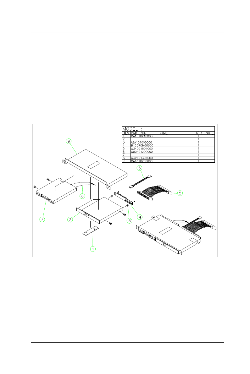
User Manual version 2305
68
8. Connect the 40-pin end of the CD-ROM cable to the
motherboard IDE 2 connector.
9. There is a 4-pin CD audio-in cable to be plugged to J2 on
the motherboard. Connect the other end of the CD-Audio
cable (6) to the 4-pin black pin connector on the CD-ROM
board.
10. Connect the other end of the FDD cable to the FDD1 on
the motherboard.
11. Fix the whole unit to the chassis and fix them together
with 3 FMS 3*5 screws.
CDROM/FDD ²Õ«~
ºÏ¾÷ªþ¥ó
slim CDROM
CDROM ¶¡¹j¬W2.5mm
MODULE CDROM-FDD
CDROM CABLE 150mm
SOUND CABLE P/H 2.54 120mm
slim FDD
FDD ³n±Æ26pin 130mm
ºÏ¾÷¬[
RISER B
5-
FIGURE 5-10: CD-ROM/FDD MODULE ASSEMBLY
APOLLO 120/150 III
Page 79

User Manual version 2305
69
FDD cable
5.9.2. External FDD Connection
1. Use the provided 15-34 pin FDD cable
(see below figure) to connect to the
system's 15-pin FDD D-sub connector
located at the rear side of the cover.
2. Connect the other end (34 pin) of the FDD cable to a
standard 3.5” FDD. Match pin 1 of the FDD and pin 1 of
the cable.
3. To drive the floppy disk drive, it will need 5V power.
Connect the provided FDD power cable to the floppy disk
drive to the +5V/12V DC-out connector to obtain 5V
power for the device.
APOLLO 120/150 III
5-
Page 80

User Manual version 2305
70
5.10. Power Module Assembly
The power supply is to be integrated with the power brackets
before it is installed to the panel PC system. The following
diagram shows the steps to assemble the ATX power module.
For the specification of the power supply, please refer to
APPENDIX.
1. Refer to Figure 5-11. Attach the power fix bracket (2) to
the power supply (3) and fix them together with 2 FMS
screws (3*5). This small bracket is used to prevent the
power supply from moving around in the power bracket.
2. Insert the power supply to power bracket (1) and fix them
together with four 3*5 screws.
3. Manage all the power cables from the power supply
properly.
4. Insert the power switch (4) to power bracket (5). The
other end of the switch cable is to be connected to the
2-pin POWER ON switch, SW1 on the motherboard.
5. Plug the ATX power cable to the ATX power connector,
PWR 3 on the motherboard.
6. Connect the big 4P end of the power cable to the HDD.
7. Connect the small 4P end the CD-ROM board.
8. The power module is to be installed to the system right on
the top of the CD-ROM/FDD module.
5-
APOLLO 120/150 III
Page 81
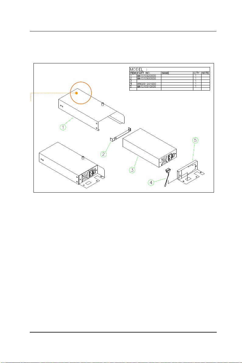
71
The power cable
coming out from
the cutout and
connected to the
MB’s ATX power
connector.
User Manual version 2305
POWER ²Õ«~
POWER©T©w¬[
POWER©T©w¬[ªþ¥ó-2
POWER SUPPLY
§ù¨¹SOFT SWITCH 120mm
POWER©T©w¬[ªþ¥ó-1(AC-AC)
FIGURE 5-11: APOLLO AC POWER MODULE
APOLLO 120/150 III
5-
Page 82

User Manual version 2305
72
5.11. Expansion Outlets & Riser Card Assembly
The APOLLO 120/150 provides PCI/ISA expansion slots for
system expansion. Via the specially designed riser card, the
system can accommodate either two PCI or one PCI plus one
ISA expansion cards; all the connectors of the expansion card
will come out from the expansion outlet on the left side of the
chassis for further cable connection.
The expansion outlet bracket has to be installed to the
system before plugging the riser card to the motherboard
PCI/ISA expansion slot.
1. When the system is reverse with the rear side facing you
and lower side near you, the expansion outlets are
located at the right upper side of the
chassis.
2. Install the expansion window (Fig. 5-1 (11))
to the chassis and fix them together with 2
FMS screws.
3. If no expansion card is plugged to the riser card, seal the
expansion outlets with the 2 metal slips located inside the
expansion outlet.
4. The riser card (8) is to be fixed with the metal bracket (9)
with two FMS screws first. Then, plug the riser card to the
onboard PCI/ISA slot. Make sure the riser card is firmly
plugged to the motherboard to prevent any bad
connection.
Due to the internal space limitation, the expansion card can
not exceed 190*120 (L*W) mm if no internal FDD is installed.
However if an internal FDD is installed, the ISA card can not
exceed 170*120 mm.
5-
APOLLO 120/150 III
Page 83

User Manual version 2305
73
5.12. Back Panel Assembly
The back panel module is the last module to be integrated to
the APOLLO main system before the plastic housing is to be
installed to the system.
1. On the I/O board, there are 6 D-SUB connectors with 2
bronze sticks on each side. Remove the 12 bronze sticks.
2. Insert the I/O board to the I/O bracket (2) and fix them
together with the 12 bronze sticks. Fix them again with
2 screws on the other side.
3. Fix the complete I/O module to the metal back panel (1)
five FMS 3*5 screws.
4. Connect one end of the 2 68-pin SCSI cables (Fig. 5-12
(4)) to the I/O board (3). Via the 2 SCSI cables, all the
onboard I/O signals are converted to the I/O board for
device cable connection.
5. Connect the other end of the two SCSI cables to the SCSI
1 and SCSI 2 connectors on the motherboard.
6. Fix the back panel module to the main system.
7. Fix a stand bracket at the bottom side of the chassis with
2 screws.
FIGURE 5-12: APOLLO BACK MODULE ASSEMBLY
APOLLO 120/150 III
APOLLO ÅK¥ó«á»\²Õ«~
ÅK¥ó«á»\
I/O »\
MODULE APOLLO IO A1.0
SCSI 68P-SCSI 68P L:180mm
5-
Page 84

User Manual version 2305
74
5.13. Stand Module Assembly
The APOLLO system comes with a versatile stand composing
of one big pedestal and one set of cable management covers.
The following figure illustrates the steps to make up the
APOLLO stand.
1. Refer to Fig. 5-13. Fix the two hinges to the hinge bracket
(5). Then fix the unit to the metal base (1). Please note
that the two hinges are different. The right side is used to
fix the hinge knob. Note that there are two avocado-shape
holes on the metal base. The two avocado holes are used
to fix the stand to the table for special application.
2. Insert the stand bottom cover (4) to the hinge module and
fix them together with four FMS 3*6 screws.
3. Fix the plastic upper cover (6) to the hinge bracket with 2
screws.
4. Insert the whole base unit to the base plastic cover (7)
and fix them together with screws to make the complete
unit a pedestal.
5. Insert the hinge knob (2) to the pedestal.
APOLLO °ò®y¼Ò²Õ
©³®yÅKªO
HINGE (¥ª) with LOCK
HINGE (¥k)
APOLLO 120/150 Âà¶b-×¹¢¤U»\
Âà¶b¤ä¬[
APOLLO 120/150 Âà¶b-×¹¢¤W»\
APOLLO 120/150 ¶ì½¦©³®y
5-
FIGURE 5-13: APOLLO PEDESTAL ASSEMBLY
APOLLO 120/150 III
Page 85

User Manual version 2305
75
To assemble the stand module (Fig. 5-14 (1)) to the main
system (2), simply tighten the two units together with 4
screws from the base. Then, install the two base back covers
(4 & 5) to the unit as shown below. There is an additional
knob in the accessory. If touchscreen is to be used with the
system, it is suggested that the additional knob is to be
assembled to the system to prevent the system from
wobbling. By swiveling the knob and pulling the base up and
down, the angle can be fixed at 45 to 900.
¥DÅé »P °ò®y²Õ¥ß
°ò®y²Õ«~
¥DÅé²Õ«~
APOLLO 120/150 ©³®y-×¹¢¤W»\
APOLLO 120/150 ©³®y-×¹¢¤U»\
FIGURE 5-14: APOLLO STAND TO MAIN SYSTEM ASSEMBLY
APOLLO 120/150 III
5-
Page 86

User Manual version 2305
76
5-
APOLLO 120/150 III
Page 87

User Manual version 2305
77
6. SYSTEM MOTHERBOARD & I/O BOARD
The system controller used in the APOLLO III
system is a special-design Celeron/Pentium® III
multimedia motherboard. All the onboard signal
is connected to an I/O board via 2 SCSI cables for
external device connection. This chapter provides
jumper definition and connector signal of the
motherboard and the I/O board.
APOLLO 120/150 III
6-
Page 88

User Manual version 2305
78
6.1. APOLLO III Motherboard
This section provides background information and detail
specification on the APOLLO 120/150 III system engine, PC
610. Sections include:
² General Information
² Features
² Specification
² Board placement & Dimension
6.1.1. General Information
The PC 610 is an Intel Celeron/Pentium III (Socket 370)
multimedia ATX motherboard with LCD/VGA controller,
Ethernet 100/10, AC97 sound, and IDE flash disk. By
integrating single chip, SiS630ST, the PC 610 provides a high
performance/low cost desktop solution.
Highly integrated, the PC 610 can adapt Intel Celeron
(66/100MHz) and Pentium III (100/133MHz) CPU. Onboard
features include four serial ports, one multi–mode Parallel
ports, a floppy drive controller and a PS/2 keyboard PS/2
mouse interface. The built-in high speed PCI IDE controller
supports both PIO and ATA 100 mode. Up to four IDE devices
can be connected, including large hard disks, CD-ROM drives
and other IDE devices. The full PC functionality coupled with
its multi-I/Os stand ready to accommodate a wide range of
PC peripherals. Compact in size and with its highly integrated
multimedia and networking functions, the PC 610 is the most
powerful PC engine to build any small footprint all-in-one PC
system for integration into any space-constricted embedded
applications.
Fully configurable and with its modular design, the PC 610 is
an ideal platform for any consumer computing applications
where space is a premium.
6-
APOLLO 120/150 III
Page 89

User Manual version 2305
79
6.1.2. Specifications
PC 610: Multimedia Intel Celeron/Pentium III Motherboard
with XGA, LCD, Dual display, Ethernet & Audio
Interface
u CPU: Intel Socket 370
• Intel Pentium III FCPGA 1GHz/133MHz
• Intel Pentium III FCPGA 650-933/133MHz
• Intel Pentium III FCPGA 500E-850E/100MHz
• Intel Celeron FCPGA 800MHz-1.10GHz/100MHz
• Intel Celeron FCPGA 533AMHz-766MHz/66MHz
• Intel Celeron PPGA 300A-533MHz/66MHz
u Main Chipset: SiS630ST
u System BIOS: Award PnP Flash BIOS
u System Memory: 1 x 168 pin DIMM sockets
supporting SDRAM up to 512MB
u L2 Cache: CPU built-in
u Standard I/O
• Serial ports x 4
• Parallel port x 1
• ATA 100/66 IDE x 2: supports up to 4 IDE devices
• FDD x 1: supports up to 2 floppy disk drives
• PS/2 Keyboard Interface x 1
• Internal Keyboard Interface x 1
• PS/2 Mouse Interface x 1
• USB Interface x 4 supporting USB 1.0 devices
u IrDA: 5-pin header with CIR support
u Ethernet
• 100/10 Base-T Ethernet
• Support WAKE-ON-LAN
APOLLO 120/150 III
6-
Page 90

User Manual version 2305
80
u Display
• LCD controller
• Integrated 2D/3D graphics engine, 4X AGP
• Share system memory architecture able to utilize
the display memory size up to 64MB
• Maximum resolution for video chipset: 640x480,
800x600, 1024x768, 1280x1024, 1600x1200,
1920x1200, True-color
• Supporting LCD/VGA dual display mode (under
Windows 98, Windows ME and Windows XP)
u Audio Function
• Full duplex and independent sample rate
converter for audio recording & playback
• Supports Microsoft DirectSound
• 3D positional audio effects
• Hi-performance, mixed-signal, stereo
• MIC-In, Speaker-Out, Line-In
• Pin header for CD-audio in
u Hardware Monitor
• Monitoring processor & system
• Monitoring 5VSB, VBAT, 1.5V, 3.3V, +5V, +12V,
-12V, and processor voltages
• Monitoring processor, chassis fan speeds
• Controlling processor and chassis fan speed and
failure alarm
• Automatic fan on/off control
• Read back capability that displays temperature,
voltage and fan speed
• Supporting Intel processor thermal diode output
(real processor temperature)
u Expansion Bus: PCI/ISA x 1
u Power: ATX power
u Dimension: 300*146 mm (L*W)
Specifications are subject to change without notice.
6-
APOLLO 120/150 III
Page 91
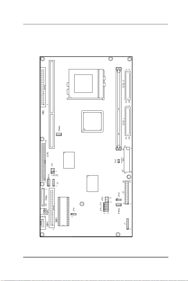
User Manual version 2305
81
6.1.3. Locating Jumpers & Connectors
The following figure helps you to locate the jumpers and
connectors on the motherboard.
APOLLO 120/150 III
6-
Page 92

User Manual version 2305
82
6.1.4. Jumpers & Jumper Setting
The table below lists the function of each jumper. The related
jumper settings are shown in the coming sections.
Jumper
JP1 DOC Address Selection
JP2 Clear CMOS
JP5 COM2 RS-232/422/485 selection
JP6 COM2 RS-232/422/485 selection
JP7 COM2 RS-232/422/485 selection
JP8 COM2 RS-232/422/485 selection
JP9 COM2 RS-232/422/485 selection
JP10 COM2 RS-232/422/485 selection
Description
6-
APOLLO 120/150 III
Page 93

User Manual version 2305
83
6.1.4.1. DOC 2000 Address Setting (JP1)
1-2 D000
3-4 D800
6.1.4.2. Clear CMOS (JP2)
1-2 Clear CMOS
3-4 Normal
6.1.4.3. COM 2 232/422/485 Setting (JP5,6,7,8,9 & 10)
COM 2 is a RS-232/422/485 serial port. JP5, 6, 7, 8, 9 and
JP10 determine the specific port type.
RS-232 RS-422 RS-485
JP5 1-2 2-3 2-3
JP6 1-2 2-3 2-3
JP7 1-2 2-3 2-3
JP8 1-2 2-3 2-3
JP9 1-2 2-3 2-3
JP10 1-2 3-4 5-6
APOLLO 120/150 III
6-
Page 94

User Manual version 2305
84
6.1.5. Connectors & Pin Assignment
The table below lists the function of each connector on the PC
610. Their corresponding pin assignments will be shown in
the following sections.
Connector Description
PWR1 Power Connector For Touch Screen
PWR2 Power Connector For CD-ROM
PWR3 ATX Power Connector
J2 CD Audio In
J7 HDD LED & ACPI LED & SMI
J8 IR/CIR connector
J9 KB/Mouse/Speaker/LED Connector
SCSI 1 I/O Connector
SCSI 2 I/O Connector
FAN1 CPU FAN Connector
FAN2 System FAN Connector
SW1 ATX Power ON/OFF
LCD LCD Connector
INV1 LCD Inverter connector
FDD1 FDD connector
IDE1 Primary IDE connector
IDE2 Primary IDE connector
COM3 Serial Port 3 (For Touch Screen)
6-
APOLLO 120/150 III
Page 95
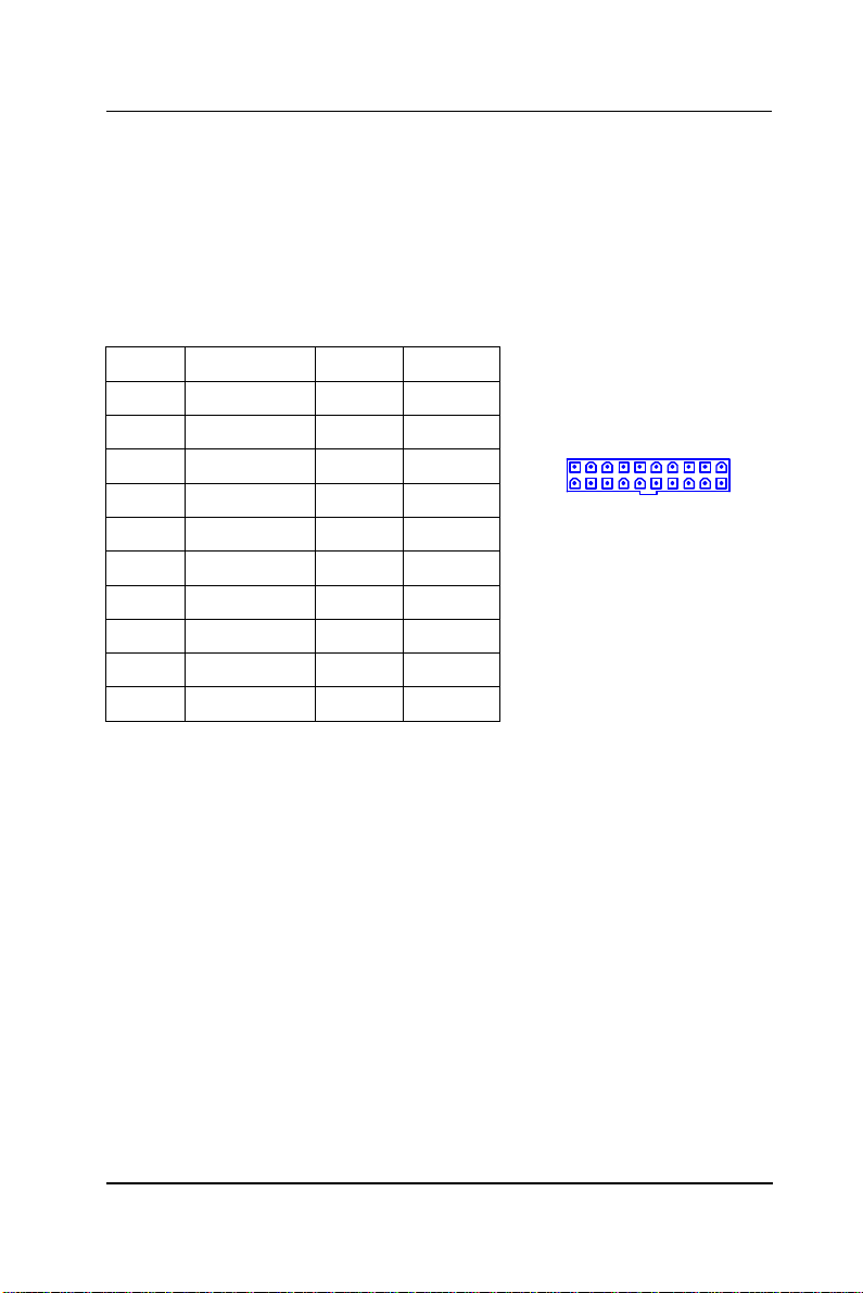
User Manual version 2305
85
6.1.5.1. PWR3: ATX Power connector
PWR 3 is a standard ATX power connector. This connector is
provided to connect to an ATX power supply. The plug of the
power supply will only insert in one orientation due to the
different hole size. Find the proper orientation and push
down the power connector firmly to make sure the pins are
aligned. Its pin assignments are listed below:
Pin # Signal Pin # Signal
1 3.3V 11 3.3V
2 3.3V 12 -12V
3 GND 13 GND
4 +5V 14 PSON#
5 GND 15 GND
6 +5V 16 GND
7 GND 17 GND
8 PWROK 18 -5V
9 SB5V 19 +5V
10 +12V 20 +5V
1 10
11 20
APOLLO 120/150 III
6-
Page 96

86
1
User Manual version 2305
6.1.5.2. J2: CD Audio IN
Pin # Signal
1 Left channel
2 CD GND
3 CD GND
4 Right channel
6.1.5.3. J7: HDD LED & ACPI LED & SMI
Pin # Signal
1 HDD LED+
2 HDD LED3 ACPI LED+
4 ACPI LED5 SMI
6 GND
6.1.5.4. J8: IR / CIR Connector
IR CIR
Pin # Signal Pin # Signal
1 5V 6 NC
2 NC 7 CIRRX
3 IRRX 8 5V (CIR)
4 GND 9 GND
5 IRTX 10 NC
10
2
4
9
1
6-
APOLLO 120/150 III
Page 97

User Manual version 2305
87
6.1.5.5. J9: Power LED & KB
Pin #
1 VCC 2 VCC
3 HDD LED 4 LAN LED
5 IR TX 6 GND
7 NC 8 NC
9 (BLK_CTRL1) 10 (BLK_CTRL2
11 GND 12 GND
13 SPK-LO 14 SPK-RO
15 SPK-LN 16 SPK-LN
17 GND 18 GND
19 EXT.KBDAT 20 INT.KBDAT
21 EXT.KBCLK 22 INT.KBCLK
23 EXT.MSDAT 24 INT.MSDAT
25 EXT.MSCLK 26 INT.MSCLK
6.1.5.6. SW1: ATX Power ON/OFF & Reset
Pin #
1 Power ON/OFF
2 GND
6.1.5.7. COM3
COM 3 is an internal RS-232 reserved for touchscreen. Its
corresponding pin assignment is listed as below;
Pin # Signal Pin # Signal
1 DCD 2 DSR
3 RXD 4 RTS
5 TXD 6 CTS
7 DTR 8 RI
9 GND 10 NC
Signal Pin # Signal
Signal
APOLLO 120/150 III
6-
Page 98

User Manual version 2305
88
6.1.5.8. LCD1: LCD Connector
Pin # Signal Pin # Signal
1 5V 2 5V
3 GND 4 GND
5 3.3V 6 3.3V
7 VBCAD 8 VBCTL0
9 P00 (B0) 10 P01 (B1)
11 P02 (B2) 12 P03 (B3)
13 P04 (B4) 14 P05 (B5)
15 P06 (B6) 16 P07 (B7)
17 P08 (G0) 18 P09 (G1)
19 P10 (G2) 20 P11 (G3)
21 P12 (G4) 22 P13 (G5)
23 P14 (G6) 24 P15 (G7)
25 P16 (R0) 26 P17 (R1)
27 P18 (R2) 28 P19 (R3)
29 P20 (R4) 30 P21 (R5)
31 P22 (R6) 32 P23 (R7)
33 GND 34 GND
35 SHFCLK 36 FLM
37 DE / M 38 LP
39 GND 40 GND
41 VBCTL1 42 VBCLK
43 GND 44 SSYNC
45 GND 46 VBHCLK
47 ENVB 48 PCIRST#
49 ENEXTPLK 50 INTA#
1
49
2
50
6-
APOLLO 120/150 III
Page 99

User Manual version 2305
89
6.1.5.9. INV1: LCD Inverter Connector
Pin # Signal
1 Backlight ADJ
2 GND
3 Backlight Enable
4 12V
6.1.5.10. FDD1: FDD connector
Pin # Signal Pin # Signal
1 VCC 2 INDEX#
3 VCC 4 DSA#
5 VCC 6 DSKCHG#
7 NC 8 NC
9 NC 10 MOA#
11 NC 12 DIR#
13 RWC# 14 STEP#
15 GND 16 WD#
17 GND 18 WE#
19 GND 20 TRAK0#
21 GND 22 WP#
23 GND 24 RDATA#
25 GND 26 HEAD#
1
4
APOLLO 120/150 III
6-
Page 100
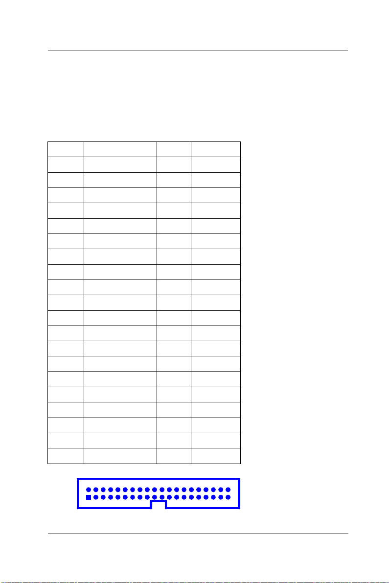
User Manual version 2305
90
2 40
6.1.5.11. IDE1/IDE2: Primary/Secondary HDD
The PC 610 provides 2 sets of 40-pin IDE connectors. The
built-in high speed PCI IDE controller supports both PIO and
ATA 100 mode. Up to four IDE devices can be connected,
including large hard disks, CD-ROM drives and other IDE
devices. Their corresponding pin assignments are listed
below;
Pin # Signal Pin # Signal
1 RESET# 2 GND
3 DATA 7 4 DATA 8
5 DATA 6 6 DATA 9
7 DATA 5 8 DATA10
9 DATA 4 10 DATA11
11 DATA 3 12 DATA12
13 DATA 2 14 DATA13
15 DATA 1 16 DATA14
17 DATA 0 18 DATA15
19 GND 20 NC
21 IDEREQ 22 GND
23 IOW# 24 GND
25 IOR# 26 GND
27 ICHRDY# 28 GND
29 DACK 30 GND
31 IDEIRQ 32 NC
33 A1 34 LID
35 A0 36 A2
37 IDECS0 38 IDECS1
39 HDD LED 40 GND
6-
APOLLO 120/150 III
 Loading...