

Page 1
X-Series
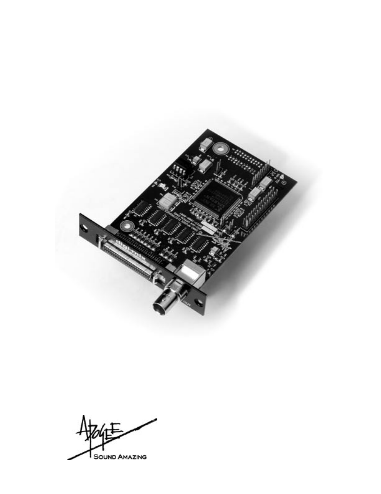
Expansion Cards
X-Digi-Mix Card
User’s Guide
v1.0 - October 2003
Page 2

Page 3

X-Digi-Mix Card
User’s Guide
Table of Contents
Installing the X-Digi-Mix card
Connections
.......................................................................................4
One Rosetta 800
Multiple Rosetta 800s
Rosetta 800s with Digidesign interfaces
Conguring X-Digi-Mix-equipped Interfaces in Pro Tools
Settings in Pro Tools
Working with Pro Tools
Software control of Apogee hardware
Working with high resolution in Mix
...................................................................................................4-6
................................................................................5
.................................................................................7
............................................................................7-8
..................................................................3
...................................................6
.............7
.......................................................7
........................................................7-8
Page 4

APOGEE ELECTRONICS
3
X-Digi-Mix – User’s Guide
Page 5

Installing the X-Digi-Mix Card
2
Your X-Digi-Mix card should include the following:
The procedure for installing the X-Digi-Mix card into an Apogee
Rosetta 800 is shown below:
3
Plastic standoff here
6
X-Digi-Mix – User’s Guide
• 1 X-Digi-Mix circuit board
• 1 X-Digi-Mix Coverplate
• 2 aluminium standoffs,
• 1 plastic standoff
• 1 user’s guide
1) Remove the top cover of the interface
2) Remove the Option Card coverplate and install the
X-Digi-Mix coverplate using the screws from the original
coverplate.
3) Remove the two interface circuit board screws as
indicated to the left, and set them aside for later use.
4) Install the two aluminium standoffs in the holes vacated
by the screws.
5) Install one end of the plastic standoff in the hole adjacent
to the connector pins of the X-Digi-Mix card: install the
other end in the hole adjacent to the mating connector.
6) Insert the BNC/Peripheral connector end of the XDigi-Mix card through the appropriate cutouts in the
coverplate, and carefully place the X-Digi-Mix connector
pins in the mating interface connector.
7) After verifying the alignment of the X-Digi-Mix connector
pins and the interface mating connector, rmly press
down on the X-Digi-Mix card, over the connector, until
the pins are completely seated in the mating connector.
8) Re-install the circuit board screws in the locations
indicated below.
8
APOGEE ELECTRONICS
3
Page 6

X-Digi-Mix – User’s Guide
APOGEE ELECTRONICS
5
X-Digi-Mix – User’s Guide
Connecting & Conguring the X-Digi-Mix-equipped
Apogee Interface
With a few simple rules it’s possible to determine the connections needed for virtually any
combination of Apogee and Digidesign interfaces.
1) The unit connected to the Digidesign PCI card installed in the computer’s rst PCI slot
(usually a Mix Core or d24 card) is the clock master of the entire system. We recommend
that an Apogee unit be installed as the Master, allowing the entire system to benet from
Apogee’s Low Jitter Clock.
2) Units connected to other PCI cards (or the “B” side of a Y cable connected to the rst PCI
card) must be clocked externally.
a. Apogee interfaces should clock to a word clock from the Master unit (if the
Master is an Apogee unit) or to a clock in the Digidesign Peripheral Cable (if the
Master is a Digidesign unit).
b. Digidesign interfaces can only clock to a Superclock (256 times the sample rate) signal.
3) When an Apogee interface is Master and a Digidesign interface is Slave, connect
Superclock Out from the X-Digi-Mix Card to Superclock In on the Digidesign interface.
4) When a Digidesign interface is Master and an Apogee interface is Slave, no clock
connections are needed; set SAMPLE RATE on the slave Apogee interface to “EXT” and
SYNC to “OPTION”.
To illustrate the necessary connections between an X-Digi-Mix-equipped Apogee interfaces, other
Digidesign compatible interfaces and Digidesign PCI cards, the Rosetta 800 is shown below in a
variety of possible setups.
Connecting One Rosetta 800
– Front Panel Setting
(ROSETTA 800)
• When connecting only 1 interface to a Pro Tools system, ensure that it is
connected to the Digidesign Mix Core or d24 card. In this conguration the
Rosetta 800 is the clock master for the entire system.
• When the Rosetta 800 is connected to the Mix Core or d24 card, the
Rosetta 800’s SAMPLE RATE and SYNC parameters are determined by
settings in the Pro Tools software. Please see the section of this manual
entitled “Working With Pro Tools” for more details.
APOGEE ELECTRONICS
4
Page 7

X-Digi-Mix – User’s Guide
Connecting & Conguring the X-Digi-Mix-equipped
Apogee Interface - continued
Connecting Multiple Rosetta 800s/AD-8000s/Trak2s
– Front Panel Settings
(ROSETTA 800)
– Front Panel Settings
(ROSETTA 800)
Master Unit
Slave Unit
• When multiple Rosetta 800s are connected to a Pro Tools system, the Master unit’s
SAMPLE RATE and SYNC parameters are determined by settings in the Pro Tools
software.
• To clock Slave Apogee interfaces, connect a BNC cable from the Master WC OUT
to the Slave WC IN, and set the Slave interface SAMPLE RATE to “EXT” and the
CLOCK SOURCE to “WC”. When distributing Word Clock to several units, we highly
recommend the use of a Master Digital Clock such as Apogee’s Big Ben. In lieu of a
Big Ben, it’s acceptable to connect a BNC “T” connector to SLAVE 1 WC IN, connect
one side to the MASTER WC OUT and the other side to the SLAVE 2 WC IN, and so
forth.
APOGEE ELECTRONICS
5
Page 8

X-Digi-Mix – User’s Guide
APOGEE ELECTRONICS
7
X-Digi-Mix – User’s Guide
Connecting & Conguring the X-Digi-Mix-equipped
Apogee Interface - continued
Connecting Rosetta 800 & Digidesign Interfaces
– Front Panel Settings
(ROSETTA 800)
(Digi-888)
Master Unit
Slave Unit
• When connecting a Rosetta 800 and a Digidesign interface, Apogee recommends that the
Rosetta 800 be connected to the Mix Core or d24 card, thereby conguring it as the clock master
of the system; the Digidesign interfaces should be connected to the remaining cards.
• Connect the X-Digi-Mix Card Superclock Out to the Digidesign interface’s Superclock In,
and chain Superclock to remaining Digidesign interfaces as instructed in the Digidesign
documentation.
• To connect a Rosetta 800 to an HD system via the Legacy port, set the Rosetta 800 to internal
clock, connect Rosetta 800 WC out to the HD interface WC in, and set the HD interface clock
source to WC in.
– Front Panel Settings
(ROSETTA 800)
(Digi-96)
APOGEE ELECTRONICS
6
Master Unit
Slave Unit
Page 9

Conguring Digidesign Pro Tools
Before your X-Digi-Mix-equipped Apogee interface will send and receive signals from Digidesign Pro
Tools software, certain hardware settings must be made in the software.
1) Before modifying hardware settings in Pro Tools, we recommend that the “DigiSetup” Preference
le be deleted to the Trash, the Trash emptied, and the computer re-booted.
2) A X-Digi-Mix-equipped Apogee interfaces uses the same Peripheral protocol as a Digidesign 888/
24, thus please consult the instructions found in your Digidesign documentation to congure Pro
Tools software for use with an 888/24.
Working With Pro Tools
For most aspects of operation such as routing, a X-Digi-Mix-equipped Apogee interfaces operates
identically to a Digidesign 888/24. Indeed, Apogee interfaces are recognized and labeled as 888/24s
in Pro Tools software.
Pro Tools software offers a limited number of hardware commands which are supported as fully as
possible by Apogee hardware. A detailed explanation of Pro Tools commands and the parameters
controlled on Apogee hardware is presented below.
X-Digi-Mix – User’s Guide
Pro Tools Command Apogee Hardware Parameter
Session Sample Rate Determines SAMPLE RATE of Master Apogee interface
Sync Mode Internal Master interface clocked internally
(i.e. SAMPLE RATE set to Session Sample Rate, EXT LED is off)
Sync Mode digital Master Interface clocked externally
(i.e SAMPLE RATE = EXT, SYNC to be selected manually)
Digital Format Ignored – digital input format must be selected manually
Input Source (Ch 1-2,3-4,5-6,7-8) Sets input pairs to either Analog or Digital input
Working with High Resolution Digital Audio in Digidesign Mix Systems
Though Digidesign Mix Systems support sample rates up to 48 kHz, it’s possible to record and play
back digital audio at sample rates up to 96kHz on a Mix system with a X-Digi-Mix-equipped Apogee
interface. This is accomplished by transmitting data to and from Digidesign hardware in a “doublewide” format, i.e one channel of 96kHz data is transmitted over 2 lines at 48 kHz. Thus, the Rosetta
800 offers 4 channels of recording and playback at 96kHz. Due to the unique nature of the data
format used, there are a few restrictions:
1) No DSP operations, including mixing, may be performed on the tracks.
2) Stereo tracks should be used, to avoid shifts in timing between the pair of tracks.
3) Cut and paste operations are allowed.
4) Though theoretical objections may arise with regard to the application of fades, many
professionals have added fades to these type of les with no adverse effects.
APOGEE ELECTRONICS
7
Page 10

X-Digi-Mix – User’s Guide
Working with ProTools - continued
To record at a higher resolution sample rate:
1) Create a Pro Tools session whose sample rate is half the desired rate (i.e., create a 44.1kHz
session to record 88.2kHz audio.
2) Once the Apogee interface has recognized the sample rate of the session, manually set it to the
desired high resolution sample rate. When using more than one Apogee interface, the Slave
interfaces must be clocked from the Master Word Clock Output.
3) For every track of high resolution audio desired, create a stereo track in the session. Routing of
audio is as depicted below:
ROSETTA 800 Analog In Session Tracks
(and I/O routing)
Input 1 Tracks 1-2 Output 1
Input 2 Tracks 3-4 Output 2
Input 3 Tracks 5-6 Output 3
Input 4 Tracks 7-8 Output 4
4) Keep in mind that it’s possible to run one interface at a lower sample rate (for example to play back
tracks), and a second interface at a higher sample rate (for example to record an analog mix of the
tracks being played back).
ROSETTA 800 Analog Out
APOGEE ELECTRONICS
8
Page 11

Page 12

X-Digi-Mix Card - v.1.0 - October 2003
Text conceived and delivered by: Roger Robindore
Graphics and product illustration by: Sean McArthur
Photos by: Bryan Walsh
 Loading...