

Page 1
Apogee PCI Card
User’s Guide
V1.3 - August 2007
Page 2

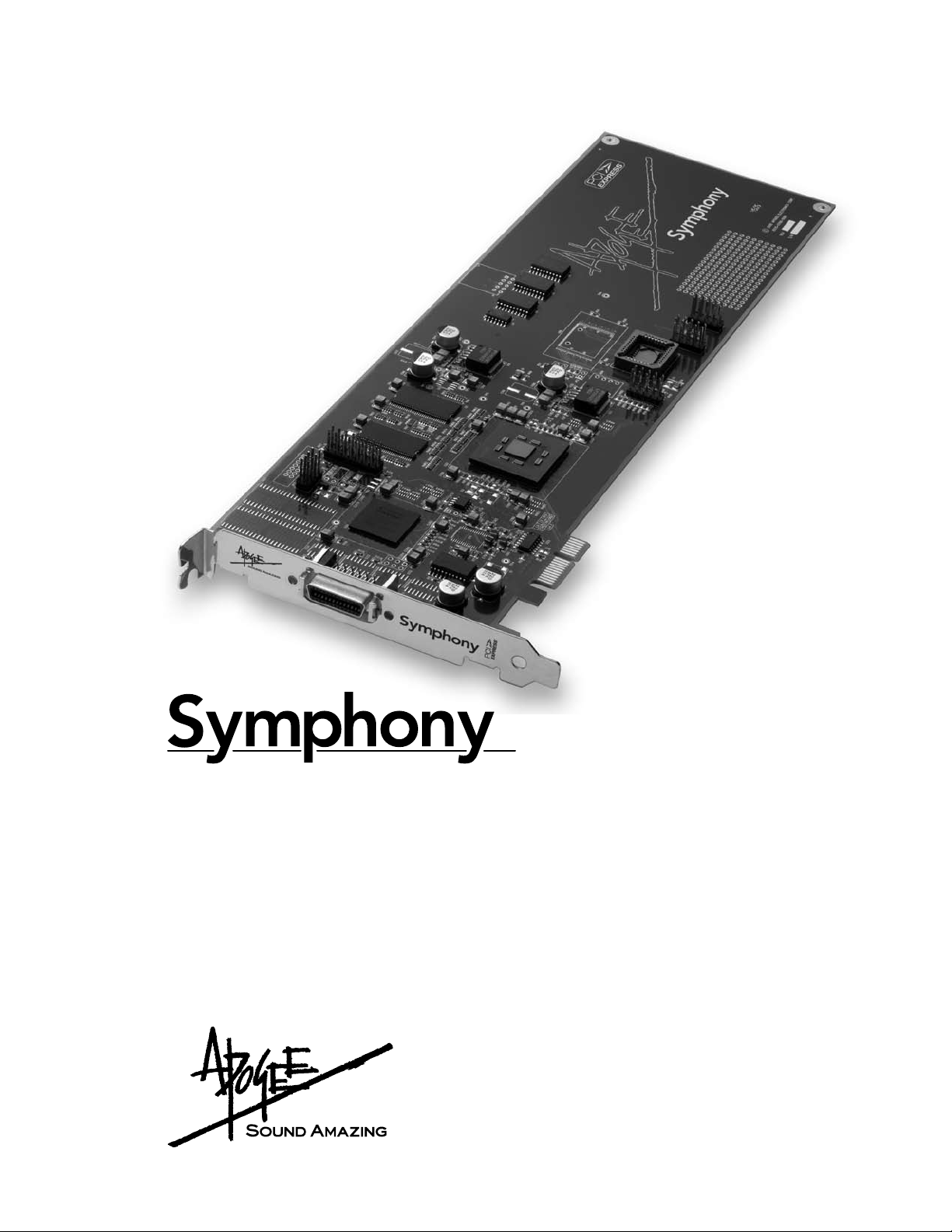
Symphony PCI card – User’s Guide
Declarations of Conformity
This device complies with Part 15 of the FCC Rules. Operation is subject to the following two conditions:
(1) This device may not cause harmful interference
(2) This device must accept any interference received, including interference that may cause undesired operation.
This equipment has been tested and found to comply with the limits of a Class A digital device, pursuant to Part 15 of the FCC Rules. These limits are designed to provide reasonable protection against
harmful inteference in a residential installation. This equipment generates, uses and can radiate radio
frequency energy and, if not installed and used in accordance with the instructions, may cause harmful interference to radio communications. If this equipment does cause harmful interference to radio or
television reception, which can be determined by turning the equipment off and on, the user is encouraged to try to correct the interference by one or more of the following measures:
1. Re-orient or relocate the receiving antenna.
2. Increase the separation between the equipment and receiver.
3. Connect the equipment into an outlet on a different circuit from that to which the receiver is
connected.
4. Consult the dealer or an experienced radio/TV technician for help.
NOTE: The use of non-shielded cable with this equipment is prohibited.
CAUTION: Changes or modications not expressly approved by the manufacturer responsible for
compliance could void the user’s authority to operate the equipment.
APOGEE ELECTRONICS
Apogee Electronics Corporation, Betty Bennett, CEO.
Industry Canada Notice
This Class A digital apparatus meets all requirements of the Canadian Interference-Causing Equipment Regulations. Cet appareil numérique de la classe B respecte toutes les exigences du Règlement sur le matérial brouilleur du Canada.
Declaration of Conformity – CE
Apogee Electronics Corporation hereby declares that the product, the Symphony PCI card, to which
this declaration relates, is in material conformity with the following standards or other normative documents:
• EN 55022-1:1998
• EN 55024-2:1998
Declaration of Conformity – Japan
Apogee Electronics Corporation hereby declares that the Symphony PCI card, to which this declaration relates, is in material conformity with the VCCI Class A standard.
Declaration of Conformity – Australia
Apogee Electronics Corporation hereby declares that the Symphony PCI card is in material conformity with AN/NZS standard requirements.
c
Page 3

APOGEE ELECTRONICS
d
Symphony PCI card – User’s Guide
APOGEE ELECTRONICS
e
Symphony PCI card – User’s Guide
Registration and Warranty Information
Be sure to register your Symphony PCI card, either by lling in the enclosed Registration Card or by completing the
on-line registration form at our Web site: http://www.apogeedigital.com/support/. If you do so, Apogee can contact
you with any update information. As enhancements and upgrades are developed, you will be contacted at the
registration address. Firmware updates are free for the rst year of ownership unless otherwise stated. Please
address any inquiries to your dealer or directly to Apogee at:
APOGEE ELECTRONICS CORPORATION,
1715 Berkeley St, Santa Monica, CA 90404, USA.
TEL: (310) 584-9394, FAX: (310) 584-9385
email: support@apogeedigital.com. Web: http://www.apogeedigital.com/
APOGEE ELECTRONICS CORPORATION warrants this product to be free of defects in material and
manufacture under normal use for a period of 12 months. The term of this warranty begins on the date of sale to
the purchaser. Units returned for warranty repair to Apogee or an authorized Apogee warranty repair facility will
be repaired or replaced at the manufacturer’s option, free of charge.
ALL UNITS RETURNED TO APOGEE OR AN AUTHORIZED APOGEE REPAIR FACILITY MUST BE
PREPAID, INSURED AND PROPERLY PACKAGED, PREFERABLY IN THEIR ORIGINAL BOX. Apogee
reserves the right to change or improve design at any time without prior notication. Design changes are
not implemented retroactively, and the incorporation of design changes into future units does not imply the
availability of an upgrade to existing units.
This warranty is void if Apogee determines, in its sole business judgment, the defect to be the result of abuse,
neglect, alteration or attempted repair by unauthorized personnel.
The warranties set forth above are in lieu of all other warranties, expressed or implied, and Apogee specically
disclaims any and all implied warranty of merchantability or of tness for a particular purpose. The buyer
acknowledges and agrees that in no event shall the company be held liable for any special, indirect, incidental or
consequential damages, or for injury, loss or damage sustained by any person or property, that may result from
this product failing to operate correctly at any time.
Warnings
FCC warning
This equipment has been tested and found to comply with the limits for a Class A digital device, pursuant to Part
15 of the FCC rules. These limits are designed to provide reasonable protection against harmful interference
when operated in a commercial environment. This equipment generates, uses, and can radiate radio frequency
energy and, if not installed and used in accordance with the instruction manual, may cause harmful interference
to radio communications. Operation of this equipment in a residential area is likely to cause harmful interference,
in which case the user will be required to take whatever measures necessary to correct the interference at his
own expense.
Copyright Notice
The Apogee Symphony PCI card is a computer-based device, and as such contains and uses software in ROMs.
This software, and all related documentation, including this User’s Guide contain proprietary information which is
protected by copyright laws. All rights are reserved. No part of the software and its related documentation may be
copied, transferred, or modied. You may not modify, adapt, translate, lease, distribute, resell for prot or create
derivative works based on the software and its related documentation or any part thereof without prior written
consent from Apogee Electronics Corporation, U.S.A.
OWNER’S RECORD
The serial number is located on the rear panel of the unit. We suggest you record the
serial number in the space provided below. Refer to it whenever you call an authorized
Apogee Electronics repair facility or the manufacturer. Please be sure to return your completed warranty card immediately!
Symphony PCI card Serial No._____________________________________________
USA: Some states do not allow for the exclusion or limitation of implied warranties or liability for incidental or
consequential damage, so the above exclusion may not apply to you. This warranty gives you specic legal
rights, and you may have other rights which vary from state to state.
Service Information
The Symphony PCI card contains no user-serviceable components: refer to qualied service personnel for repair
or upgrade. Your warranty will be voided if you tamper with the internal components. If you have any questions
with regard to the above, please contact Apogee.
In the event your Symphony PCI card needs to be upgraded or repaired, it is necessary to contact Apogee prior
to shipping, and a Return Materials Authorization (RMA) number will be assigned. This number will serve as a
reference for you and helps facilitate and expedite the return process. Apogee requires that shipments be prepaid and insured — unless otherwise authorized in advance.
IMPORTANT: ANY SHIPMENT THAT IS NOT PRE-PAID OR IS SENT WITHOUT AN RMA NUMBER WILL
NOT BE ACCEPTED.
Purchase Date__________________________________________________________
Dealer_________________________________________________________________
Phone_________________________________________________________________
Address________________________________________________________________
CAUTION:
Any changes or modications not expressly approved by APOGEE ELECTRONICS
CORPORATION could void your authority to operate this equipment under the FCC rules.
Please register this unit by lling in the included registration card, or registering online at
http://www.apogeedigital.com/support/register.php Please read this manual – if you call for
technical support, we’ll assume that you have. There will be a quiz.
Page 4
User’s Guide
Table of Contents
Introduction
System Requirements
Overview
On-board Jumpers
Installing Symphony PCI Cards
Installing the X-Symphony card
PC32 Connections
Word Clock Connection on Apogee Interfaces
Installing the Symphony Core Audio Driver
ConguringYourDAW
Apple Logic Pro
iTunes
Maestro Control
VBus
Preformance Tuning
Interface Connections Chart: Standard Routing
Interface Connections Chart: Advanced Option Routing
Troubleshooting
Clock Source
....................................................................................................................1
.................................................................................................1
...........................................................................................................................1
........................................................................................................1
...............................................................................2
.............................................................................3
.........................................................................................................4
................................................5-6
....................................................6
.............................................................................................7
.......................................................................................................7
.....................................................................................................................7
.........................................................................................................8-11
...........................................................................................................8
........................................................................................................................10
...............................................................................................10
.........................................12-15
................................................................................................................18
............................16-17
Page 5
Symphony PCI card – User’s Guide
APOGEE ELECTRONICS
Introduction
The Symphony PCI card system allows the connection of up to 96 channels of 192kHz Apogee conversion to an Apple Macintosh computer.
The system consists of:
• Symphony PCI-e or PCI-x card;
• X-Symphony X-Option card (installed in Apogee interfaces)
• PC-32 cables
• Maestro routing and low-latency mixer application.
System Requirements
1. Apple PowerMac G5 1.8Ghz or higher with PCI-e or PCI-x slots or Mac Pro.
1 GB of RAM required, 2 GB RAM recommended.
2. OS X 10.4.0 or greater
Overview
Here are the steps to complete to get your Symphony PCI card-based audio system up and running:
1. Congure on-board jumpers (p.1).
2. Install Symphony PCI cards into Macs (p.2); install X-Symphony cards into Apogee interfaces (p.3).
3. Connect PC32 cables between Apogee Interfaces (p.4).
4. Connect word clock cables between interfaces (p.5).
5. Install driver on the Mac (p.6).
6. Congure computer and DAW software to utilize Symphony hardware (p.7).
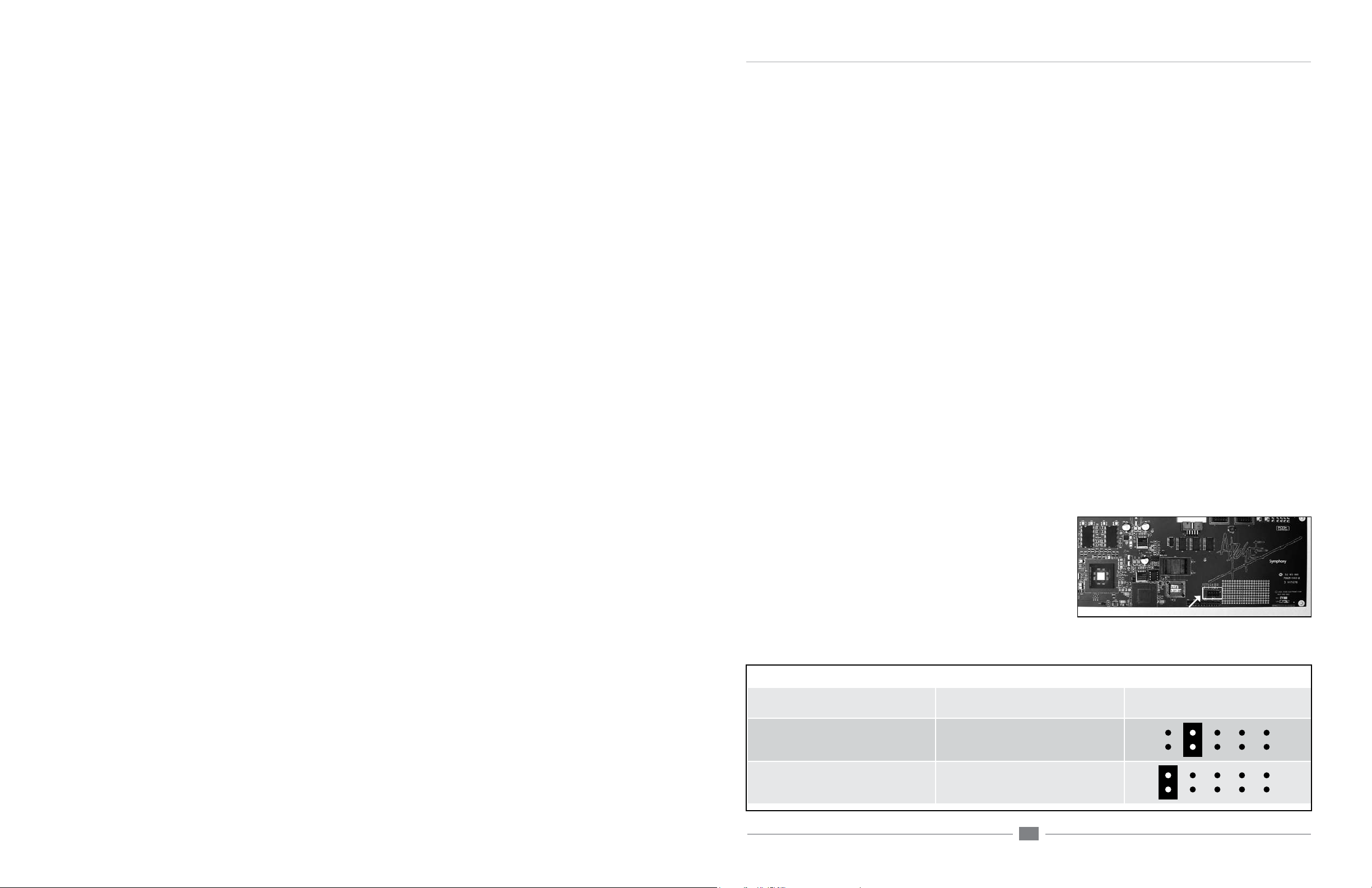
On-board Jumpers
Before installing Symphony PCI cards into your Mac, it’s necessary to assign a unique ID for each card using the block of
jumpers indicated in gure 1.
1. Remove the Symphony card from its anti-static bag, paying
careful attention to not touch the on-board components or
the gold connector pins.
2. Determine the appropriate PCI slots and jumper settings for
each card using gure 2 below.
Symphony Card PCI Slot to use Jumper Block
First Card Lowest number slot available
Second Card Adjacent to First Card
Third Card Adjacent to Second Card
FIGURE 1
no jumpers (from the factory a
jumper is installed on 1 pin only)
Jumper location
FIGURE 2
1
Page 6

APOGEE ELECTRONICS
2
Symphony PCI card – User’s Guide
APOGEE ELECTRONICS
3
Symphony PCI card – User’s Guide
Installing Symphony PCI Cards
Installing the X-Symphony card
1. As a safety precaution, unplug the computer’s AC cable.
2. To avoid electrostatic damage to the Symphony card, it is recommended that a grounded anti-static wrist
strap be used when installing the card.
3. Remove the Mac’s side cover (and air deector, if installing the card in a G5).
4. Remove the screw(s) securing the port access cover(s) of the required PCI slots and set them aside for later
use. Remove the port access cover(s).
5. After verifying jumper settings of the PCI card, align the card edge connector with the desired PCI slot and
press the card rmly into place until the gold pins of the edge connector are just visible. Be sure to insert the
end of the card without the connector into the appropriate card guide. If the card does not slide into place
with minimal effort, remove the card, check alignment and check for foreign objects. Don’t force the card into
place.
6. Re-install the access cover screw to secure the Symphony PCI card.
7. If multiple Symphony cards have been installed, connect the supplied ribbon cable between each PCI card as
shown below, making sure to align the key on the ribbon cable connector to the slot on the PCI card socket. If
only two Symphony cards are installed, use the connector on each end of the ribbon connector.
8. Re-install the Mac’s side panel (and air deector, if appicable)
2
4
3
Your X-Symphony card should include the following:
1 X-Symphony circuit board
1 X-Symphony Coverplate
2 aluminium standoffs
1 plastic standoff
1 Remove the top cover of the host interface.
2 Remove the Option Card coverplate, and set aside the screws for
later use.
3 Remove the two interface circuit board screws indicated at left, and
set them aside for later use
4 Install the two aluminium standoffs in the threaded holes vacated
by the screws.
5 On the X-Symphony card, install the plastic standoff in the hole
adjacent to the multi-pin motherboard connector.
6 Insert the Port connector end of the X-Symphony card through the
host unit back panel, and carefully place the multi-pin motherboard
connector in the mating connector found on the host interface
motherboard.
7 After verifying the alignment of the multi-pin and the mating con-
nectors, rmly press down on the X-Symphony card, over the connector, until the pins are completely seated in the mating connector.
8 Re-install the circuit board screws from Step 3 in the locations
indicated below.
9 Install the X-Symphony Coverplate, and secure it to the host inte-
face using two screws from Step 2.
10 Replace the top cover of the host interface.
Installation of Symphony PCI-E card
6
Multiple Symphony cards connected
by ribbon cable
5
9
9
8
Page 7

APOGEE ELECTRONICS
4
Symphony PCI card – User’s Guide
APOGEE ELECTRONICS
5
Symphony PCI card – User’s Guide
PC32 Connections
It’s possible to connect Apogee AD16X, DA16X, Rosetta 800 and Rosetta 200 interfaces to Symphony
PCI cards in a wide array of congurations, for a total of 32 channels of simultaneous input and output per PCI
card. Please consult the Interface Connections Chart on pages 8-13 for a complete list of all the possible com-
binations of Apogee interfaces that may be connected per PCI card.
PLEASE NOTE: For the Symphony system to operate correctly, each PCI card must be connected to at
least one hardware interface.
The Interface Connections Chart depicts important aspects of each possible combination, including:
1) The order in which interfaces should be connected. As shown in the example below of an AD16X
and DA16X in Standard routing, the computer should be connected to the AD16X’s Main port, and the AD16X’s
Thru port connected to the DA16X’s Main port.
2) The connection between the interfaces’s I/O and the Symphony system’s I/O. As shown in the
example below, the AD16X’s 16 analog inputs are connected to Symphony inputs 1-16, and Symphony outputs
1-16 are connected to the DA16X’s analog outputs. In this example, Symphony I/O 17-32 are unused, though
they still appear in your software I/O list.
INTERFACE SET CHANNELS IN USE
AD-16X & DA-16X
From Computer
M
T
M
T
INPUT
OUTPUT
Regardless of the Apogee hardware used, PC 32 cables should be connected as shown below, where the
Symphony PCI card is connected to the rst unit’s X-Symphony Main port, the rst unit’s Thru port is connected
to the second unit’s Main port, and so on until all interfaces are connected.
1-16 17-32
AD-16X #1
DA-16X #1
Word Clock Connection on Apogee Interfaces
In the Symphony system the rst interface serves as the clock master to the entire system, and may be set to
Internal or External clock in Apogee’s Maestro application. All remaining interfaces must receive a word clock
signal synchronous with the rst interface’s clock source, whether Internal or External.
When a Symphony system is booted, the rst interface will switch to the clock source specied in Maestro
(Internal or External) while the remaining interfaces will switch automatically to their external word clock source.
The two most common ways to accomplish the necessary word clock connections are depicted below.
Using a Master Clock (such as Apogee’s Big Ben)
1 Connect a word clock cable between outputs
of the master clock and each interface’s word
clock input, and terminate the input with a 75
ohm load.
2 Boot your Mac, open the Maestro app, and
set Clock Source Select for the rst interface
to External. All remaining interfaces should
switch to their external word clock source.
3 If interfaces aren’t displayed in Maestro, select
Tools > Reset Symphony Clocking and click
on External Clock.
4 When opening CoreAudio applications,
ensure that the master clock is running at
the same sample rate as the session you’re
opening.
Figure A. Optimum clocking conguration using BIG BEN
Big Ben
Interface 1
Interface 2
Interface 3
Interface 4
(Symphony PCI card installed in computer)
(X-Symphony Cards installed in Apogee
converters)
Clocking to the rst interface
1 Install BNC “T connectors on the word clock
inputs of the second, third and fourth interfaces
(if present). Connect a word clock cable from
the rst interface’s word clock output to the
Interface 1
Interface 2
BNC “T” connector on the next interface, from
that interface to the next, until all the word
Interface 3
clock inputs have been chained together, as
shown in gure B. Terminate the word clock
input of the last interface with a 75 ohm load.
2 Boot your Mac, open the Maestro app, and set
Clock Source Select for the rst interface to
Figure B. Correct clocking conguration to the master device’s
Interface 4
clock output using BNC “T“ connectors
Internal. All remaining interfaces should switch
to their external word clock source.
3 When opening CoreAudio applications, the rst interface should switch to the same sample rate as
the session you’re opening, and all remaining interfaces should follow.
Page 8

APOGEE ELECTRONICS
6
Symphony PCI card – User’s Guide
APOGEE ELECTRONICS
7
Symphony PCI card – User’s Guide
ConguringYourAudioSoftwareWord Clock Connections - Multiple Symphony PCI Cards
Regardless of the number of Symphony PCI cards to which hardware interfaces are connected, each
hardware interface must receive a synchronous word clock. For example in the system shown below, the rst two
interfaces are connected to one Symphony PCI card and the second two interfaces are connected to a second
PCI card, but all four interfaces are connected to the same clock source.
Apple Logic Pro
In Apple Logic Pro, start a session and follow these steps:
1. Open Audio > Audio Hardware and Drivers > Drivers > CoreAudio and check the
“Enabled” box.
2. Select “Apogee Symphony” in the “Driver” eld, and click “Try (Re)-Launch” when prompted by
Logic.
3. In Logic’s Mixer page, verify that
32 inputs and outputs are available
per installed Symphony PCI card.
Please note that the number of
I/O available in Logic remains the
same regardless of the number of
interface I/O channels connected to
the card.
Installing the Symphony Core Audio Driver
Symphony Core Audio drivers must be installed on the computer to interface Symphony PCI hardware to Core
Audio compatible software. This driver may be found on the Apogee Software CD included with the Symphony
PCI card. More driver information may be found at Apogee’s website here:
www.apogeedigital.com/symphonysupport
To install the driver:
1. Insert the CD into your Mac’s optical disc drive.
2. Double click on the CD’s icon when it appears on the desktop of your Mac.
3. Follow the instructions provided by the installer program.
4. Re-start your Mac after installation is complete.
Important note: Sleep settings
Due to the processor intensive nature of computer-based digital audio systems, it’s required that OSX’s
“Sleep” functions be disabled.
1. Under the Apple menu, open the System Preferences window and click on the Energy Saver icon. In the
Energy Saver window, set both computer and display sleep sliders to “Never” and uncheck the hard disk
sleep box.
2. On a G5 : Under the “Options” tab, set Processor Performance to “Highest”.
iTunes
1. From your Mac’s Menu bar Apple menu, open the System Preferences window, and click on the Sound
icon; in the Sound Preferences window, click on the Output tab and select Apogee Symphony.
2. Open iTunes, select an audio le, and initiate playback; signal is sent to outputs 1-2 of the rst connected
Apogee interface.
Page 9

APOGEE ELECTRONICS
8
Symphony PCI card – User’s Guide
APOGEE ELECTRONICS
9
Symphony PCI card – User’s Guide
Overview
Maestro Control - Symphony/Symphony Mobile
1
1. Interface Drop Down menu – The Interface drop down menu, found in the upper left corner of each Maestro window,
is used to select the Apogee interface whose settings are displayed in that window. Once selected, an icon representing the interface appears at the top of the window. When hardware connected to a Symphony card is selected,
Interface names are displayed in the following format:
Symphony card to which
the unit is connected
Unit model and Routing (AD-DA16X)
2
2. Identify Unit – This feature is disabled when interfaces connected via Symphony PCI are selected.
3. Clock Source Select - This drop down menu is used to set the clock source of the selected interface to Internal or
3
External. When set to Internal, the selected interface derives clock from an internal crystal; when set to External,
clock source selection varies according to the digital input options of each Apogee interface, as described below.
Rosetta 800/200 – when set to External, the specic source (ADAT/SMUX, AES or Word Clock input) must be
manually selected on the Rosetta’s front panel.
AD16X – when set to External, the AD16X accepts clock from its Word Clock input.
DA16X – when set to External, the specic source, either word clock or digital input, must be manually selected
on the DA16X’s front panel.
Unit number
Overview
1
2
3
This setting is grayed out when the clock source is automatically set by the hardware system. For example, in a multi-
interface Symphony PCI/Mobile system, Clock Source Select is greyed out when any but the rst interface connected directly to the Symphony card is selected in the Interface drop down menu.
Page 10

APOGEE ELECTRONICS
10
Symphony PCI card – User’s Guide
APOGEE ELECTRONICS
11
Symphony PCI card – User’s Guide
Overview
Maestro Control - Symphony/Symphony Mobile
VBus - Apogee’s VBus creates virtual hardware buses to allow the routing of signals within one audio application or
between different audio apps. For example, it’s possible in Logic Pro to record a submix of multiple audio tracks onto a
new audio track as described below - not possible without VBus. It’s also possible to route between two audio apps by
selecting a VBus output in the source app and a VBus input in the destination app.
4
To engage VBus and specify the number of desired buses, open Apogee’s Maestro application, select one of
the Apogee interfaces connected to the Symphony PCI card, and open the Maestro Control Panel. In the VBUS
Selections drop down menu, select the number of virtual buses desired. As these buses don’t use much CPU power,
the only reason to select fewer buses would be to maintain order in the I/O lists of your audio apps. Up to 32 Vbuses
per Symphony PCI card are possible
5
In order for VBus I/O to appear in your audio application’s I/O list as VBus In 1-2, 3-4, etc, it’s necessary to specify
the use of the Symphony driver’s names in the applications’s I/O list. For example in Logic Pro, open Audio>Audio
Conguration>View>I/O Labels and Option-click on all the I/O found under the Driver’s I/O Label column.
As an example of how to use VBus, let’s record a submix of drums onto a new stereo audio track in Logic Pro.
Open Maestro and select 8 Channels under the VBus Selections menu.
6
In Logic’s Track Mixer, set the outputs of the individual drum audio tracks to VBout 1/2
Create two audio tracks (or one stereo track) and set their inputs to VBin 1 and VBin 2.
Record-enable the new track and commence recording – the new track will record the mix of the individual drum
tracks.
Overview
4
7
5
7
Performance Tuning allows the adjustment of Symphony driver buffers to take advantage of the latest Intel Macs’
increased CPU power.
Set Performance Tuning to High Performance when using Symphony on an Intel Mac; this reduces buffer sizes
and ensures the lowest latency through the Symphony system.
Set Performance Tuning to Standard when using Symphony on G5 PowerPC Macs. Though Symphony buffers are
set higher, latency is still quite low.
Performance Tuning is set in addition to the buffers typically found in digital audio applications. If audible clicks and
pops are encountered, rst raise the driver buffer size in the audio application. Apogee’s extensive testing of this
driver indicates that software buffers will “run out” before the Symphony driver buffers controlled by Performance
Tuning. If problems persist set Performance Tuning to Standard.
6
Page 11

APOGEE ELECTRONICS
12
Symphony PCI card – User’s Guide
APOGEE ELECTRONICS
13
Symphony PCI card – User’s Guide
Interface Connections Chart: Standard Routing
The following chart depicts all possible congurations of Apogee interfaces that may be connected per Symphony PCI card. Under “Channels in Use”, the mapping of the interface’s I/O to the Symphony card’s I/O is
indicated.
Please note that AD and DA16X possible congurations change based on the whether interfaces are in Standard or Advanced Routing.
INTERFACE SET CHANNELS IN USE
AD-16X & DA-16X
From Computer
M
T
From Computer
M
T
M
T
From Computer
M
T
From Computer
M
T
M
T
INPUT
OUTPUT
INPUT
OUTPUT
INPUT
OUTPUT
INPUT
OUTPUT
1-16 17-32
AD-16X #1
1-16 17-32
AD-16X #1
1-16 17-32
DA-16X #1
1-16 17-32
DA-16X #1
AD-16X #2
DA-16X #2
Interface Connections Chart: Standard Routing (continued)
INTERFACE SET CHANNELS IN USE
AD-16X & DA-16X continued
From Computer
M
T
M
T
From Computer
M
T
M
T
M
T
From Computer
M
T
M
T
M
T
From Computer
M
T
M
T
M
T
M
T
INPUT
OUTPUT
INPUT
OUTPUT
INPUT
OUTPUT
INPUT
OUTPUT
1-16 17-32
AD-16X #1
DA-16X #1
1-16 17-32
AD-16X #1
DA-16X #1
1-16 17-32
AD-16X #1
DA-16X #1
1-16 17-32
AD-16X #1
DA-16X #1
AD-16X #2
DA-16X #2
AD-16X #2
DA-16X #2
Page 12

APOGEE ELECTRONICS
14
Symphony PCI card – User’s Guide
APOGEE ELECTRONICS
15
Symphony PCI card – User’s Guide
Interface Connections Chart: Standard Routing (continued)
INTERFACE SET CHANNELS IN USE
AD-16X, DA-16X & ROSETTA 800
From Computer
M
T
M
T
M
T
From Computer
M
T
M
T
M
T
From Computer
M
T
M
T
M
T
M
T
ROSETTA 800 and AD-16X & DA-16X
From Computer
M
T
M
T
From Computer
M
T
M
T
M
T
From Computer
M
T
M
T
From Computer
M
T
M
T
M
T
INPUT
OUTPUT
INPUT
OUTPUT
INPUT
OUTPUT
INPUT
OUTPUT
INPUT
OUTPUT
INPUT
OUTPUT
INPUT
OUTPUT
1-16 17-32
DA-16X #1
ROSETTA 800 #1 ROSETTA 800 #2
1-16 17-32
AD-16X #1
DA-16X #1
ROSETTA 800 #1
1-16 17-32
AD-16X #1
DA-16X #1
ROSETTA 800 #1 ROSETTA 800 #2
1-16 17-32
ROSETTA 800 #1
1-16 17-32
ROSETTA 800 #1
ROSETTA 800 #2
1-16 17-32
ROSETTA 800 #1
1-16 17-32
ROSETTA 800 #1
ROSETTA 800 #2
AD-16X #1
AD-16X #1
DA-16X #1
DA-16X #1
Interface Connections Chart: Standard Routing (continued)
INTERFACE SET CHANNELS IN USE
ROSETTA 800 and AD-16X & DA-16X continued
1-16 17-32
ROSETTA 800 #1
1-16 17-32
ROSETTA 800 #1 ROSETTA 800 #2
1-16 17-32
AD-16X: Analog In
AD-16X: Digital Out
ROSETTA 800 #1
1-16 17-32
ROSETTA 800 #1
1-16 17-32
ROSETTA 800 #1 ROSETTA 800 #2
1-16 17-32
ROSETTA 800 #1 ROSETTA 800 #2 ROSETTA 800 #3
1-16 17-32
ROSETTA 800 #1 ROSETTA 800 #2 ROSETTA 800 #3
ROSETTA 800
From Computer
M
T
M
T
M
T
From Computer
M
T
M
T
M
T
M
T
From Computer
M
T
M
T
From Computer
M
T
From Computer
M
T
M
T
From Computer
M
T
M
T
M
T
From Computer
M
T
M
T
M
T
M
T
INPUT
OUTPUT
INPUT
OUTPUT
INPUT
OUTPUT
INPUT
OUTPUT
INPUT
OUTPUT
INPUT
OUTPUT
INPUT
OUTPUT
AD-16X #1
DA-16X #1
AD-16X #1
DA-16X #1
ROSETTA 800 #4
Page 13

APOGEE ELECTRONICS
16
Symphony PCI card – User’s Guide
APOGEE ELECTRONICS
17
Symphony PCI card – User’s Guide
Interface Connections Chart: Advanced Option Routing
INTERFACE SET CHANNELS IN USE
AD-16X & DA-16X
From Computer
M
T
From Computer
M
T
From Computer
M
T
M
T
From Computer
M
T
M
T
INPUT
OUTPUT
INPUT
OUTPUT
INPUT
OUTPUT
INPUT
OUTPUT
1-16 17-32
AD-16X: Analog In
AD-16X: Digital Out
1-16 17-32
DA-16X: Digital In
DA-16X: Analog Out
1-16 17-32
AD-16X: Analog In AD-16X: Analog In
1-16 17-32
DA-16X: Digital In DA-16X: Digital In
Interface Connections Chart: Advanced Option Routing (continued)
INTERFACE SET CHANNELS IN USE
AD-16X, DA-16X & ROSETTA 800
From Computer
M
T
M
T
M
T
From Computer
M
T
M
T
M
T
AD-16X: Digital OutAD-16X: Digital Out
DA-16X: Analog OutDA-16X: Analog Out
AD-16X (Standard routing) DA-16X (Advanced routing)
From Computer
M
T
M
T
INPUT
OUTPUT
INPUT
OUTPUT
INPUT
OUTPUT
1-16 17-32
AD-16X: Analog In
AD-16X: Digital Out
ROSETTA 800 #1 ROSETTA 800 #2
1-16 17-32
DA-16X: Digital In
DA-16X: Analog Out
ROSETTA 800 #1 ROSETTA 800 #2
1-16 17-32
AD-16X: Analog In DA-16X: Digital In
DA-16X: Analog Out
AD-16X, DA-16X & ROSETTA 800
From Computer
M
T
M
T
From Computer
M
T
M
T
From Computer
M
T
M
T
INPUT
OUTPUT
INPUT
OUTPUT
INPUT
OUTPUT
1-16 17-32
AD-16X: Analog In DA-16X: Digital In
1-16 17-32
AD-16X: Analog In
AD-16X: Digital Out
ROSETTA 800 #1
1-16 17-32
DA-16X: Digital In
DA-16X: Analog Out
ROSETTA 800 #1
DA-16X: Analog OutAD-16X: Digital Out
Page 14

Symphony PCI card – User’s Guide
APOGEE ELECTRONICS
Troubleshooting
Q: Two messages “An error has occurred…” and “Symphony is now congured correctly” are alternately displayed onscreen.
How can I stop this and get the system to settle down?
A: There are a few reasons this may occur:
There may be a mismatch exists between the CoreAudio sample rate (as indicated in the OS X utility Audio Midi
Setup) and the hardware’s sample rate. This occurs most frequently when the rst hardware interface is clocked
externally to a Master clock such as Apogee’s Big Ben. Be sure that the Master clock is set to the same sample rate
as the CoreAudio sample rate.
All Hardware interfaces aren’t synchronized – verify that all hardware interfaces are receiving clock from the master
clock.
Q: My Apogee interfaces aren’t appearing in Maestro – how can I remedy this?
A: Interfaces won’t appear in Maestro until they are properly connected and clocked; make sure that the Lock
indications on each hardware interface indicate a stable lock at the correct sample rate.
If some interfaces are appearing but others aren’t, be sure that the conguration of interfaces connected is supported,
i.e listed in the Interface Connections Chart on 10-15.
Keep in mind that setting an AD or DA16X in Advanced routing will change the number of interfaces that may be
connected. Thus, 2 ADs and 2 DAs in Standard routing will all appear in Maestro, while only the rst AD/DA pair
appears when set in Advanced routing.
Q: When Apogee hardware interfaces don’t appear in Maestro, how can I set the rst interface to External clock?
A: When rst conguring a Symphony setup with an external Master clock, one may encounter the situation whereby
the rst interface must be set to External Clock in Maestro, but can’t appear in Maestro until clock is correctly
congured. To overcome this conundrum, select the Maestro menu item Tools > Reset Symphony Clocking; a dialog
box appears offering the options to set clock on the rst hardware interface to External or Internal.
18
Page 15

Symphony PCI card USER’S GUIDE - v1.3 August 2007
Text conceived and delivered by: Roger Robindore
Graphics and illustrations by: Sean McArthur
 Loading...