

Page 1
DDAA--22000000
20-bit Stereo
Reference
Digital/Analog
Converter - Switcher
with UV22
Operating Manual
Rev 1.0 — November 1998
Page 2

DA-2000 Operating Manual
Manual written by Julio Alvarez.
Produced and edited by Richard Elen.
UV22 is a Registered Trademark of Apogee Electronics Corporation. All other trademarks are property of their
respective holders.
Technology within the DA-2000 including the Low Jitter Clock may be covered by one or more patents that are
the property of Apogee Electronics Corporation.
Registered User Customer Support:
For customer support, please call (310) 915-1000
or email support@apogeedigital.com
You can register your DA-2000 on the Internet: visit http://www.apogeedigital.com/register.html
Features and specifications subject to change without notice.
© 1998 APOGEE ELECTRONICS CORPORATION
3145 Donald Douglas Loop South
Santa Monica
California 90405
USA
Tel: +1 310/915-1000
Fax: +1 310/391-6262
Email: info@apogeedigital.com
Web: http://www.apogeedigital.com/
This manual is copyrighted ©1998 by APOGEE ELECTRONICS CORPORATION, with all rights reserved. Under
copyright laws, this manual may not be duplicated in whole or in part without the written consent of Apogee.
Part Number MANUAL–DA-2000 Rev 1.0 November 1998
Page 3
DA-2000 Operating Manual
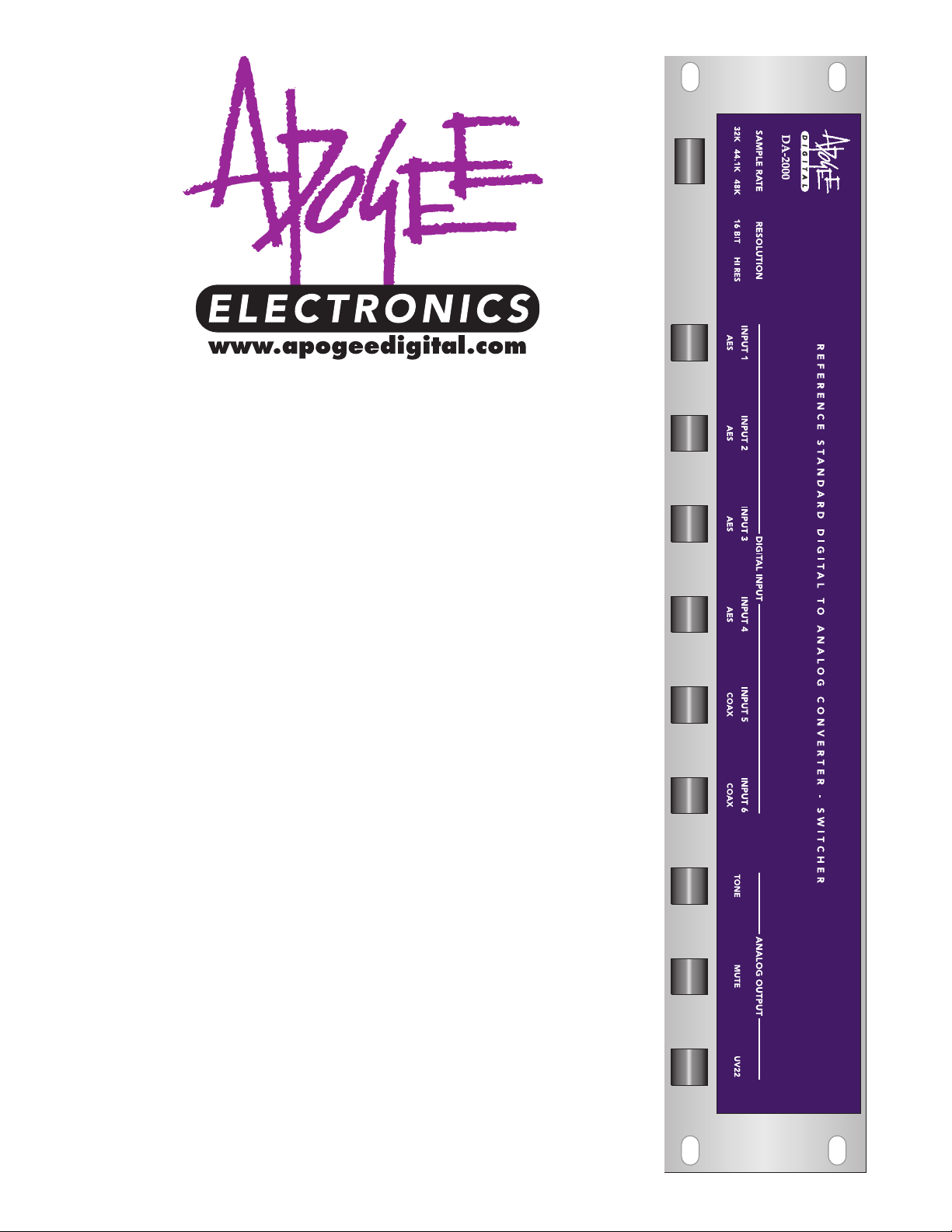
The Apogee DA-2000
20-bit, Stereo
Reference Digital/Analog
Converter-Switcher
Page 4

DA-2000 Operating Manual
Page 4
Registration and Warranty Information
Be sure to register your DA-2000, either by filling in the enclosed Registration Card or
by completing our on-line registration form at our Web site: http://www.apogeedigital.com/register.html. If you do so, Apogee can contact you with any update information. As
enhancements and upgrades are developed, you will be contacted at the registration
address. Firmware updates are free for the first year of ownership. Please address any
inquiries to your dealer or directly to Apogee at:
APOGEE ELECTRONICS CORPORATION, 3145 Donald Douglas Loop South, Santa Monica, CA 90405, USA.
TEL: (310) 915-1000, FAX: (310) 391-6262
email: support@apogeedigital.com. Web: http://www.apogeedigital.com/
APOGEE ELECTRONICS CORPORATION warrants this product to be free of defects in material and manufacture under normal use for a period of 12 months. The term of this warranty begins on the date of sale to the
purchaser. Units returned for warranty repair to Apogee or an authorized Apogee warranty repair facility will be
repaired or replaced at the manufacturer’s option, free of charge. All units returned to Apogee or an autho-
rized APOGEE repair facility must be prepaid, insured and properly packaged. Apogee reserves the right
to change or improve design at any time without prior notice. Design changes are not implemented retrospectively, and the incorporation of design changes into future units does not imply the availability of an upgrade
to existing units.
This warranty is void if Apogee determines, in its sole business judgment, the defect to be the result of abuse,
neglect, alteration or attempted repair by unauthorized personnel.
The warranties set forth above are in lieu of all other warranties, expressed or implied, and Apogee specifically disclaims any and all implied warranty of merchantability or of fitness for a particular purpose. The buyer
acknowledges and agrees that in no event shall the company be held liable for any special, indirect, incidental
or consequential damages, or for injury, loss or damage sustained by any person or property, that may result
from this product failing to operate correctly at any time.
USA: Some states do not allow for the exclusion or limitation of implied warranties or liability for incidental or
consequential damage, so the above exclusion may not apply to you. This warranty gives you specific legal
rights, and you may have other rights which vary from state to state.
Service Information
If the DA-2000 is kept in a clean environment free of excess dust, moisture and heat, it will give years of trouble-free service. The only components with a limited life are the electrolytic capacitors used. These are of high
quality and will give many thousands of hours service.
The DA-2000 contains no user-serviceable components: refer to qualified service personnel for repair or
upgrade. Your warranty will be voided if you tamper with the internal components. If you have any questions
with regard to the above, please contact Apogee by phone at (310) 915-1000, by fax at (310) 391-6262, or via
email to support@apogeedigital.com.
In the event your DA-2000 needs to be upgraded or repaired, it is necessary to contact Apogee prior to shipping, and a Return Materials Authorization (RMA) number will be assigned. This number will serve as a reference for you and helps facilitate and expedite the return process.
Apogee requires that shipments be pre-paid
and insured
— unless otherwise authorized in advance. IMPORTANT: Any shipment that is not pre-paid or is
sent without an RMA number will not be accepted.
Page 5

DA-2000 Operating Manual
Page 5
Declarations of Conformity
Declaration of Conformity—FCC
Apogee DA-2000
This device complies with Part 15 of the FCC Rules. Operation is subject to the following two conditions:
(1) This device may not cause harmful interference, and
(2) This device must accept any interference received, including interference that may cause undesired operation.
This equipment has been tested and found to comply with the limits of a Class B digital device, pursuant to Part
15 of the FCC Rules. These limits are designed to provide reasonable protection against harmful inteference in
a residential installation. This equipment generates, uses and can radiate radio frequency energy and, if not
installed and used in accordance with the instrcutions, may cause harmful interference to radio communications.
If this equipment does cause harmful interference to radio or television reception, which can be determined by
turning the equipment off and on, the user is encouraged to try to correct the interference by one or more of
the following measures:
1. Re-orient or relocate the receiving antenna.
2. Increase the separation between the equipment and receiver.
3. Connect the equipment into an outlet on a different circuit from that to which the receiver is connected.
4. Consult the dealer or an experienced radio/TV technician for help.
NOTE: The use of non-shielded interference cable with this equipment is prohibited.
CAUTION: Changes or modifications not expressly approved by the manufacturer responsible for compliance
could void the user’s authority to operate the equipment.
Apogee Electronics Corporation, 3145 Donald Douglas Loop South, Santa Monica, CA 90405.
Brent Elder, VP Engineering.
Industry Canada Notice
This Class B digital apparatus meets all requirements of the Canadian Interference-Causing Equipment
Regulations.
Cet appareil numérique de la classe B respecte toutes les exigences du Réglement sur le matérial brouilleur du
Canada.
Declaration of Conformity – CE
Apogee Electronics Corporation hereby declares that the product, the DA-2000 system, to which this declaration relates, is in material conformity with the following standards or other normative documents:
• EN50081-1/EN55022; 1995
• EN50082-1/IEC 801-2, 3, 4; 1992
following the provisions of:
• 73/23/EEC – Low Voltage Directive
• 89/336/EEC – EMC Directive
Page 6

DA-2000 Operating Manual
Page 6
Caution
Any changes or modifications not expressly approved by APOGEE ELECTRONICS CORPORATION could void
your authority to operate this equipment under the FCC rules.
OWNER’S RECORD
The serial number is located on the rear panel of the unit. We suggest you record the serial number in the space
provided below. Refer to it whenever you call an authorized APOGEE repair facility or the manufacturer. Make
sure that you return your completed warranty card immediately!
Model No. DA-2000 Serial No. ________________ Purchase Date __________________
Dealer____________________________________________________
Page 7

DA-2000 Operating Manual
Page 7
Table of Contents
Registration and Warranty Information............................................................................................................4
Service Information...........................................................................................................................................4
Declarations of Conformity ..............................................................................................................................5
Owner’s Record.................................................................................................................................................6
Warnings ...........................................................................................................................9
Environmental Warnings...................................................................................................................................9
Power Warning..................................................................................................................................................9
FCC Warning.....................................................................................................................................................9
Copyright Notice ..............................................................................................................................................9
Specifications ..................................................................................................................10
Unpacking .......................................................................................................................10
Getting Started...............................................................................................................10
Quick Start Guide ...........................................................................................................11
Installation.......................................................................................................................13
Operating Voltage ..........................................................................................................................................13
Overview.........................................................................................................................14
Professionals Talk About Apogee ...................................................................................15
Understanding Digital Audio Interconnects ...................................................................16
Dither and UV22 .............................................................................................................20
Revision History..............................................................................................................21
Page 8

DA-2000 Operating Manual
Page 8
This page intentionally left blank.
Page 9

Warnings
CAUTION: To reduce the risk of electrical shock, do not remove the cover. No user serviceable parts inside;
refer servicing to qualified personnel.
WARNING: To reduce the risk of fire or electrical shock, do not expose this appliance to rain or moisture.
This symbol, wherever it appears, alerts you to the presence of uninsulated dangerous voltage inside
the enclosure—voltage that may be sufficient to constitute a risk of shock.
This symbol, wherever it appears, alerts you to important operating and maintenance instructions in
the accompanying literature. Read the manual.
Environmental warnings
• Never touch the AC plug with wet hands.
• Do not use this unit in damp areas or near water.
• Avoid damaging the AC plug or cord and potentially causing a shock hazard.
• If liquids spill into or onto the DA-2000, disconnect the power and return to your dealer for servicing.
• This unit should only be connected to an AC power supply of the correct voltage. Check with your dealer
if in doubt.
• Precautions should be taken so that the grounding or polarization of the AC power is not defeated.
• Unplug the AC cord when the unit is unused for long periods of time.
• This unit should only be cleaned as recommended by the manufacturer, or damage to the finish may result.
• To avoid potential damage to your unit, only use in areas where proper ventilation and moderate tempera-
tures are assured.
Power warning
AC voltage ratings for electrical power vary from area to area. Severe damage to your unit is possible
if your DA-2000 is configured incorrectly for your local power. If in doubt, consult an Apogee dealer.
Instructions for checking and changing the power input voltage setting are provided on page 13.
FCC warning
This equipment has been tested and found to comply with the limits for a Class A digital device, pursuant to Part 15 of the FCC rules. These limits are designed to provide reasonable protection against
harmful interference when operated in a commercial environment. This equipment generates, uses,
and can radiate radio frequency energy and, if not installed and used in accordance with the instruction manual, may cause harmful interference to radio communications. Operation of this equipment in a residential area
is likely to cause harmful interference, in which case the user will be required to take whatever measures may
be required to correct the interference at his own expense.
Copyright Notice
The Apogee DA-2000 contains and uses software in ROMs. This software, and all related documentation,
including this Owner’s Manual, contain proprietary information which is protected by copyright laws. All rights
are reserved. No part of the software and its related documentation may be copied, transferred, or modified.
You may not modify, adapt, translate, lease, distribute, resell for profit or create derivative works based on the
software and its related documentation or any part thereof without prior written constent from Apogee
Electronics Corp, U.S.A.
DA-2000 Operating Manual
Page 9
Page 10

DA-2000 Operating Manual
Page 10
DA-2000 Specifications
Sampling Rate 32–54 kHz
Converter System 8x oversampling 20-bit delta-sigma
Digital Inputs 2 coaxial S/PDIF, 4 balanced XLR AES/EBU
Analog Outputs 2 balanced, 1 unbalanced
THD+N 97 dB at 1 kHz
Frequency Response (44.1kHz)
20-20kHz, ±.0.5 dB
S/N Ratio 108.5 dB A-weighted, 106 dB unweighted
THD <0.005%, 20-20 kHz
Internal recovered clock jitter
<30 picoseconds RMS
Crosstalk 110 dB typical, 20-20 kHz
Dimensions 19 x 4 x 12.5 (WHD)
Weight 20 lbs. (9.1 kg)
De-emphasis 50µSec/15µSec
Unpacking
Your DA-2000 is packed in a foam-lined shipping container. Be sure to save the container for any further shipment of the unit.
Included Accessories:
Operation Manual
Warranty Card
AC Cable
Getting Started Quickly
Your DA-2000 is shipped from Apogee ready to go. It has spent at least 48 hours ‘burning in’. This burn-in procedure involves powered operation at elevated temperatures to eliminate units that would possibly fail due to
infant mortality.
We recommend you read the entire manual before using your DA-2000 (or at the very least, the Quick Start
Guide on the next page). If you are anxious to get started, you will find the operation is intuitive. We suggest
you take the following steps, referring to the diagram on the following page:
1. Connect the left and right analog XLR outputs
➍, the phono outputs ➎, or the Fischer outputs ➌ on the rear
panel to your equipment. Be sure NOT to have both the XLR and Fischer outputs connected to your equipment simultaneously as this may cause impedance mismatch problems. The left and right analog output
polarity for the XLR and Fischer connectors is set at the factory for pin 2 hot. If your system is pin 3 hot,
make a special cable that connects pin 2 on one end to pin 3 on the other end. The DA-2000 provides both
balanced and unbalanced outputs for your convenience.
2. Connect the digital audio output from your digital source to either the AES/EBU female XLR connector
➒
or the S/PDIF female BNC connector ➑.
3. Turn the front panel POWER selector switch to ON (press right side of the switch).
4. Press the DIGITAL INPUT selector button (
④ or ⑤) to select the appropriate digital input. When an AES input
is selected, the selected male XLR connector is active, accepting AES/EBU format. When an S/PDIF input is
selected, an S/PDIF RCA connector is active, accepting S/P DIF format.
Your DA-2000 should now be functioning.
Page 11

DA-2000 Operating Manual
Page 11
Quick Start Guide
①
②
③④
⑤
⑦⑧
❶
❷
❸
❹
❹❺
❻
❼
❽
❽
❾
Congratulations on your purchase of one of the finest digital to analog converters available. This quick-start guide will get you up and running quickly so you can start enjoying
the DA-2000 right away. Please take a few minutes to fill out and return the warranty
registration card.
The Front Panel
(See upper illustration above)
①Power button: Powers the unit on and off. Press the right side of the button for power on.
Press the left side for power off.
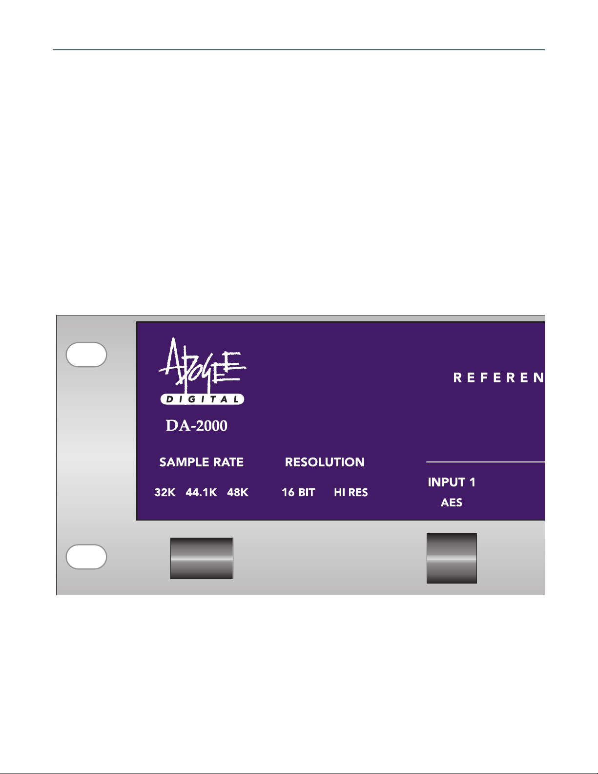
②Sample rate indicator: Indicates the sample rate (sampling frequency) of the selected dig-
ital input source. The DA-2000 will accept any sampling frequency between and including
32kHz and 54kHz. The common sample rates are 32kHz, 44.1kHz (for Compact Disc), and
48kHz.
③Word length (bit resolution) indicator: Indicates the word length or “resolution” of the
selected digital input source. “High” indicates an input with a word length above 16 bits
(i.e., 20 or 24 bits).
④AES input selectors: These four buttons select, as the input source to the DA-2000, one of
the four corresponding AES/EBU inputs on the back panel
❾.
⑤Coax S/PDIF input selectors: These two buttons select, as the input source to the DA-2000,
one of the two corresponding coaxial inputs on the back panel
❽.
Calibration test tone output selector: Selects a 1 kiloHertz test tone from the internal oscil-
lator as the analog output. The level of the test tone can be adjusted by turning the rear
panel “Test Tone” level selector
❼.
⑦Output mute selector: Mutes the analog outputs.
Page 12

DA-2000 Operating Manual
Page 12
⑧UV22 selector: Switches-in Apogee’s proprietary UV22 process on the digital inputs for
ultra-linear conversion.
The Rear Panel
(See lower illustration overleaf)
❶Fuse cage and AC voltage selector: When opened, the AC fuses and AC voltage selector
wheel are exposed. To change a fuse, pull the gray fuse trays straight out and replace the
appropriate fuse. To change the AC voltage selections, pull the wheel or “drum” entirely
out of the enclosure, turn to the desired voltage selection, and re-install with the desired
voltage setting facing the back of the unit so that it is displayed through the window when
the door is closed. DO NOT TURN THE WHEEL WHILE IT IS STILL INSIDE THE ENCLO-
SURE. This will damage the contacts behind the wheel.
❷AC cable jack: Receptacle for the AC power cord.
❸Left and Right Fischer analog outputs: Connect these outputs to the Fischer analog inputs
of your amplifier or pre-amplifier. The DA-2000 is shipped from the factory for pin 2 hot
unbalanced operation. For pin 3 hot operation, make special polarity-reversal cables that
have pin 2 on one end connected to pin 3 on the other end and vice versa.
NOTE: Do not
run the DA-2000 with the Fischer and XLR outputs simultaneously connected to your amplifier or pre-amplifier. Use only one set of outputs at a time.
❹Left and Right XLR analog outputs: Connect these outputs to the XLR analog inputs of
your amplifier or pre-amplifier. Use wide bandwidth 110Ω Apogee Wyde-Eye A/D XLR
cables for best sound (Apogee part # WE-XX-3.0).
NOTE: Do not run the DA-2000 with the
Fischer and XLR outputs simultaneously connected to your amplifier or pre-amplifier. Use
only one set of outputs at a time.
❺Left and right RCA analog outputs: Connect these outputs to the RCA analog inputs of
your amplifier or pre-amplifier. We recommend wide bandwidth 75Ω
Apogee Wyde-Eye
A/D
coaxial cables for superior quality results (Apogee part # WE-RR-3.0).
❻Analog calibration pots: These two indented multi-turn pots are used to calibrate the level
of the analog outputs. In conjunction with the internal test tone oscillator and an analog
meter, the DA-2000 can be calibrated to an operating output level in the range from
+8.11dBu to +15.85 (with a 0dBFS digital input/test tone). Using a trimming tool or small
flathead screwdriver, turn clockwise for an increase in output level and counterclockwise for
a decrease in output level. From the factory, the DA-2000 is calibrated to 0dBFS = +10dBu.
❼Test Tone level selector: Selects the level of the test tone from the internal oscillator in
dBFS (full scale or “digital” scale). So, for example, when calibrating the DA-2000 for an
operating level of -6dBFS = +4dBu (0 dBFS = +10 dBu factory setting), set the TONE LEVEL
to “-12” and your analog meter should read –2dBu.
❽Coaxial digital inputs (S/PDIF): Inputs 5 and 6 are S/PDIF format coaxial digital inputs using
RCA-type connectors. Connect the S/PDIF coaxial digital output from your digital device to
these inputs. We recommend wide-bandwidth 75Ω
Apogee Wyde-Eye A/D coaxial cables
for superior sound (Apogee part # WE-RR-3.0).
❾XLR digital inputs (AES/EBU): Inputs 1, 2, 3, and 4 are AES/EBU format digital inputs on
XLR connectors. Connect the AES/EBU digital output from your digital device to these
inputs. For superior results, we recommend wide bandwidth 110Ω
Apogee Wyde-Eye A/D
XLR cables for best sound (Apogee part # WE-XX-3.0).
Page 13

Installation
Your DA-2000 is designed for free standing or rack-mount operation. When used in a free standing mode,
make sure it is sitting on its rubber feet. It is important to allow for adequate ventilation around the unit. Do
not block any of the ventilation holes on the side panels.
As shipped from the factory, the DA-2000 has blanking panels over the rack ears where the rack-mounting
holes are situated. For rack-mounted operation, remove the blanking panels by unscrewing the two hex screws
on each panel using a 1/16” hex driver. When mounting the unit into a rack, make sure that the unit is not tightly sandwiched between other items in the rack so as to restrict adequate ventilation.
Operating Voltages
AC Mains operation
Your DA-2000 will operate at 100V, 120V, 220V, or 240V. To change the voltage setting on your unit:
1. Open the fuse cage door by inserting a flat-head screwdriver into the slot at the top of the plastic door (1)
and pull back until the door snaps open.
2. Then pull the voltage selector wheel or “drum” entirely out of the enclosure,
3. Turn to the desired voltage selection, and
4. Re-install with the desired voltage setting facing the back of the unit so that it is displayed through the win-
dow when the door is closed.
NOTE: Do not turn the wheel while it is still inside the enclosure as this could damage the contacts
behind the wheel.
NOTE: In some countries, the standard voltage output is 230V. If your wall plug outputs 230V,
select the 240V setting on the DA-2000.
To change a fuse, pull the gray fuse-trays straight out and replace the appropriate fuse.
• For 100VAC and 120VAC operation use a 750mA (3/4 A) slow blow fuse.
• For 220, 230, and 240VAC operation use a 250mA (1/4 A) slow blow fuse.
NOTE: The 120VAC fuse specification silk-screened on the back of the DA-2000 differs from this recommendation. Please use the fuse value recommended above.
DA-2000 Operating Manual
Page 13
Page 14

DA-2000 Operating Manual
Page 14
Overview
Features
The Apogee DA-2000 is a professional reference standard digital to analog converter enclosed in a convenient,
robust package that can be rack mounted or used freestanding.
The DA-2000 incorporates the results of two years research into uncolored, faithful audio reproduction, and
features a number of unique, proprietary Apogee developments. These include:
• Relay protection that prevents power-up thumps and provides fault protection.
• Back panel calibration pots for output level adjustment.
• Latest D/A converter technology with 8X oversampled digital data driving two 20-bit dual Digital to Analog
converters. These dual converters utilize the latest segmented techniques to eliminate the usual large transitions around zero, thus providing excellent low level performance in addition to the inherent high level
performance.
• Apogee CC768 Low Jitter Clock that locks to any sampling rate from 32kHz to 54kHz for uncolored high
frequency sound reproduction. Accurate timing regeneration, without the use of narrow band crystals, permits full sonic performance even in vari-speed operation.
• Apogee’s model 964-IV-63 current to voltage and filter module matches our latest filter advances with a
unique proprietary circuit that converts high speed electrical currents from the DACs into the necessary
voltage with none of the shortcomings of traditional op-amp approaches. This lightning-fast circuit has no
feedback, yet still delivers distortion performance that rivals the measurement ability of our test equipment.
• Apogee’s award-winning UV-22 bit-reduction technology. UV-22 is used in approximately 80% of albums
mastered in North America to smooth the harsh edges of digital audio (read “About UV-22” further on).
• 1 kHz sine wave test tone to calibrate analog equipment connected to the DA-2000 to a standard reference.
The level of the test tone can be set via a back panel indented trim pot to one of eight standard reference
levels (in dBFS).
Calibration
The DA-2000 is shipped from the factory calibrated to 0dBFS = +10dBu (-6dBFS = +4dBu pro reference standard). It is ready to use without needing calibration. If you your listening environment necessitates a different
calibration, please follow the steps below:
1. Feed the digital input a 1 kHz digital test tone generated either from a console (or any other tone genera-
tor) or a pre-recorded source (keep in mind that the DA-2000’s internal test tone oscillator is used to calibrate equipment connected downstream of the DA-2000 and is not part of this discussion). The level of the
tone should be the digital level (in dBFS) that is required to produce a +4dBu level (0VU on an analog meter)
from the analog outputs. For example, as discussed above, the unit is calibrated from the factory so that a
–6dBFS tone fed to the digital inputs produces a +4dBu level from the analog outputs. For louder analog
outputs (i.e., more gain from the internal amps), feed a lower level tone (-8dBFS, -10dBFS, etc.). Conversely,
for quieter analog outputs, feed a higher level tone (-5dBFS, -4dBFS, etc.). With a 0dBFS (full-scale digital)
input tone, the DA-2000 can be calibrated in a range from +8.11 to 15.85dBu output analog level.
2. Press the appropriate front panel ‘DIGITAL INPUT’ button to select the correct input source.
3. Feed the analog outputs to an analog meter that is referenced to 0VU = +4dBu.
4. With the desired digital level fed to the digital inputs, turn the back panel indented trim pots
➏ clockwise
for increase in output level and counter-clockwise for decrease in output level. Turn the trim pots in the
appropriate direction until the meter reads “0VU”.
Page 15

DA-2000 Operating Manual
What the Professionals Have to Say
about Apogee Products
“I have been listening to A/D and D/A converters since 1977. Each time a new converter came out, it sounded better than the one before it. Last week in Nashville, I compared three of the best converter packages available. The very best converter package should do absolutely nothing—the playback of the digitally stored data
should sound no better and no worse than the original source. All I want is a straight wire. The clear winner of
the Nashville test was the Apogee converter package. I had put off buying my own converters for a couple
years. After the Nashville test, I had no more excuses.”
—Roger Nichols, Recording Engineer and Producer
“The DA-1000 lets me hear exactly what I’m putting on the CD Master. The clarity and lack of coloration is
remarkable. There is no harshness, thinness or artificial warmth. The image is stable and defined. Each instrument is in its correct position without having its size changed or its edges blurred. Attacks and decays are accurate. Reverb and delays sound correct without drying up.”
—Ted Jensen, Sterling Sound; New York, NY
“In our tests, the Apogee AD-500 retained more of the ambience and definition than ever before and was
discernable all the way to the end product, the CD disc. We feel that it is now possible to bring forth more of
the information that was originally intended for the CD consumer.”
—Bernie Grundman, Grundman Mastering; L.A., CA
“I have lots of conversion equipment, but with the DA-1000, it’s as if I’m listening directly to the analog
source.”
—Stephen Marcussen, Precision Mastering; L.A., CA.
“How do I get the highest quality analog to digital conversion without having to lug DAT machines all over
the planet, and still maintain some sort of consistency...? Your marvelous, portable AD-500 and DA-1000 Digital
Converters! The Apogees have made my life so much simpler.”
— Bob Clearmountain, Recording Engineer and Producer
“After listening to virtually all of the currently available D/A converters, the Apogee is by far the most accurate!”
— Glenn Meadows, Mastering Engineer; Masterfonics, Nashville, TN.
“As you know, we have been very pleased with the DA-1000. With the addition of the AD-500, we have
added a new standard of musicality and sonic accuracy. When we compared the sound
of the entire digital chain using the AD-500 and DA-1000, the end result was the closest to the original
source we have ever heard!”
—Steve Hall, Future Disc Systems; L.A., CA.
Page 15
Page 16

A User’s Guide to Understanding
Digital Audio Interconnects
Digital Audio without Making Your Eyes Glaze Over
Yo u’ve probably read, or at least started to read many articles on digital audio. Like me, you may be guilty
of skipping the technical diagrams and jumping to the last page for the conclusions. Understanding how digital audio works is akin to getting into the details of how MIDI controls musical instruments — it’s handy infor-
mation but not necessary for making music. Most digital audio users’ eyes glaze over when discussing the technical aspects of the subject. On the other hand, discussing why one digital audio box won’t talk to another can
make the same eyes bug out and face turn red! Many of us have experienced the frustration of trying to make
one piece of digital audio gear connect to another without success. Digital audio is not so new anymore, so its
reasonable to assume that interconnects should be “no brainers”. Because they aren’t, requires some under-
standing of what makes them tick so we can get the most out of them. This section will give you insight to deal
with the peculiarities of digital interconnects without the usual technical smoke screen.
The Difference Between Good Old Analog and Digital Audio
Sound is transmitted through air as movement of individual air molecules. A microphone turns this movement of air into a changing voltage, which represents the air movement. This changing voltage is called an analog of the air movement. Sound analogs can also be mechanical, such as a phonograph groove, electrical current, magnetic field, optical energy, or any continuously varying representation.
Digital audio uses numbers to represent sound. These numbers have to be big enough to accurately capture
the smallest and biggest details in sounds. The same numbers also need to be changed fast enough so our ear
is not aware of them stepping by. You are probably aware that cartoons consist of a sequence of individual
drawings changing fast enough to give the illusion of motion. If we slow the sequence of drawings down, the
image starts to flicker like the old movies and motion becomes jerky.
To fool our eyes into seeing fluid motion, the images need to change from one to the next at around 25 per
second. There are some motion picture systems such as the one from Showscan in Culver City, CA that increase
the rate to 60 per second, resulting in an amazingly grain-less and fluid motion.
The frozen visual images of individual movie frames are analogous to the individual numbers of digital audio.
Our ear doesn’t get fooled into thinking that these numbers sound real until they change at around 32,000 times
a second. The individual numbers are called “samples” and represent audio in narrow slivers of time. The rate
these frozen slices of audio change is called the sample rate
A sample rate of 32,000 is used in digital broadcasting applications. Compact Discs use a 44,100 sample rate.
You will often see these sample rates represented as kHz or kilohertz (k - One Thousand; Hz - Cycles per second). A 44.1 sample rate is 44.1 kHz or 44,100 samples per second. These individual samples are different to
the musical instrument or vocal “samples” used in assembling music tracks. Such “samples” are made up of
strings of the individual “slices of time” digital samples much as a video clip is a sequence of individual video
frames.
You can see it takes a lot of numbers in the digital world to represent an analog version of the same sound.
An analog signal path may need a frequency response of 100,000 Hertz to faithfully reproduce 20,000 Hertz
audio. A digital signal path for the same 20,000 hertz audio requires a frequency response of several million
Hertz. Bandwidth is a measure of the lowest to the highest frequency a path can handle. The wide bandwidth
required for digital audio is due to the way the individual numbers are transmitted across an interconnect. There
are a number of different methods of making digital audio connections inside equipment and externally to other
devices.
Digital Audio Interconnects
In the early days of digital audio there was no accepted standard for interconnecting different devices, so
the manufacturers invented their own schemes. A interconnect needs to pass the individual numbers of each
sample along with timing information and any useful control information such as if pre-emphasis was applied or
not (see later).
DA-2000 Operating Manual
Page 16
Page 17

The numbers of digital audio are transmitted in binary form. Instead of using our familiar ten-finger oriented decimal numbers, we substitute one-finger binary numbers. Any decimal number can be represented as a
binary number and vice versa. The big advantage of using binary coding to represent digital audio samples is
each individual digit of a complete binary number takes only one of two values instead of the ten used in our
familiar decimal method of counting. Binary digits are called bits and, because they have only two values or
states, can be easily represented by electronic circuits as either on or off, high or low voltage etc. The most
common digital audio numbers in use today are 16 or 20 bits long, with a smaller percentage of recorders and
workstations capable of handling or storing more.
All At Once or A Bit At A Time
When manufacturers had to come up with schemes to interconnect their products, before they could agree
on a standard (pre AES/EBU), the main requirement was to minimize the number of interconnections. When
making interconnections within a digital device, it is usually most efficient to move the numbers around as complete chunks of the individual bits. Sixteen bit systems can use 16 separate lines to transfer entire sample in single steps. This is known as parallel operation. A parallel interconnect between different audio devices is cumbersome, requiring over 32 connections for a stereo 16 bit system plus additional lines for grounds, timing and
control information. A more efficient method is to send the 16 bit numbers across one wire, one bit at a time.
This is called a serial interconnect and can be visualized as sending individual bits down a hose and reassembling them into complete numbers at the other end.
It’s important to know when the 16 bit numbers start and finish to correctly unravel them at the other end,
so timing information is also included as either a separate connection or included with the 16 bit audio and identified with an additional unique pattern of bits. You can think of the timing as the pulse of a digital audio system; every time it beats, it signals a sequence of events such as the beginning of a transfer of a sample, one bit
at a time. The main pulse is at the sample rate, beating at 44,100 times a second for a CD player. In addition to
the sample rate beat, there are additional higher frequency pulses used to co-ordinate all the activity going on
between the slower sample rate timing. You could visualize this relationship in musical terms as a one bar loop
with the main pulse on one and the other as 1/32 note pulses. The high frequency pulses are often called the
bit clock, which is passed across interconnects in one form or another.
Its All In The Timing
A drummer’s timing can make the difference between good music and a memorable hit. Digital audio needs
good timing to make it from one place to another with uncompromised sound quality. The timing in interconnect is used to unscramble all the bits for accurate recovery of the exact samples transmitted. The timing also
needs to be very regular. Timing jitter is any irregularity in the timing passed across an interconnect. If the samples become messed up in the interconnect, the effects are usually very audible, varying from occasional clicks
to a loud, harsh fuzz. Timing jitter can cause more subtle effects. In digital to analog converters for example,
the location of instruments across the audio sound stage can become less focused. (Note: A “sound stage” is
the mental picture you form when you listen to a piece of music in stereo or surround and localize the various
instruments and vocals in space: closing your eyes can help form the image). A well-defined sound stage has
width, depth, and focused locations all defined by subtle reflections, reverb tails and tonal quality in a stereo
mix.
These Interconnects Sound Different!
You may have heard critical digital audio listeners complain “if digital audio is so perfect then how come it
sounds different when I use different interconnects?” Some experts will tell them it must be their imagination
because if the numbers are sent correctly on each interconnect they both must sound the same. That makes
sense but it’s only part of the story…
When a digital to analog converter receives the samples from an interconnect, it must also extract the timing information and regenerate its own timing “clock”. A good analogy is a drummer playing to a click track. If
the drummer is good, they can nail the basic tempo of the click and then add in faster patterns of their own,
such as a sixteenth note hi-hat. When digital devices receive the clock from an interconnect, they lock up to the
sample rate tempo and add faster multiples many times higher than the drummer’s sixteenth-note example.
Now imagine what would happen to the drummer’s playing if we put slight, random variations in his click track
Page 17
AD-8000 Operating Manual
Page 18

DA-2000 Operating Manual
reference. The drummer would try to follow the changing tempo but because the changes were unpredictable,
they would overshoot the click tempo as it moves up and down. The random click track variations around a perfectly steady tempo is called tempo jitter. The poor drummer ends up with worse jitter in their timing unless
they can ignore the small changes and play to the average.
The problem of interconnects affecting the sound can be traced to jitter in the timing of the digital to analog playback. Each time digital audio timing is passed through additional circuits, it picks up slight variations
around the original perfect timing. The amount of timing jitter added through successive stages depends on
the type of circuits. Inside products, different computer logic families used for digital calculations, add varying
amounts of jitter. Noise on power supplies and grounds, nearby clocks with similar harmonics, AC mains and
external interference can all add dreaded jitter to perfect timing. Some of it is random and some has specific
frequency content. When the internal timing is passed to another device over an interconnect, different types
of connections add more or less jitter. A short AES/EBU connection over high quality data cable will pick up less
jitter than the same signal run through a bunch of microphone cable, XLR connectors and patch bays. A consumer coaxial wire connection is usually cleaner than the consumer ‘TOSLink’ optical version, mainly due to the
slower response time of the optical transmitter and receiver.
When the circuits in digital to analog converters (D/As) recover the timing, they are often negatively influenced by the jitter picked up along the way, much like our miserable drummer trying to follow the varying click
track. When the recovered timing starts to wobble around as it tries to track the jittery input, it modulates the
analog sound coming out of D/As, causing all sorts of subtle negative effects such as changes in the stereo
image and tonal quality. An interesting source of jitter in AES/EBU digital interconnects is due to the changing
samples and subcode information. A 1kHz digital audio tone causes 1kHz jitter.
Different interconnects do not sound different if the timing circuits of the reference D/A are designed to
ignore any jitter and the samples are correctly transmitted. Jitter also has a big influence on the quality of analog to digital converters with very similar side effects, which unfortunately are there forever after.
AES/EBU Interface
AES/EBU, AES3-1985, ANSI S4.40-1985, AES3-1992, EBU Tech.3250- E.CCIR Rec.647 (1986), CCIR Rec.647
(1990) Confused? Well, don’t be. These are the different standards we lump together and call AES/EBU, the
connection designed to standardize plugging one digital box to another. AES is the Audio Engineering Society
and EBU is the European Broadcasting Union. These organizations and others have worked very hard to bring
us a standard method of sending professional digital audio across a single interconnect with maximum compatibility. Generally the approach work well as long as the potential weaknesses are kept in mind when stringing things together. A better understanding of how two channels of digital audio flow across a single connection helps highlight the pitfalls.
Electrically, the AES/EBU signal is tailored to use cable similar in design to microphone cable to go from here
to there. Microphone cable normally carries analog audio on a twisted pair of wires enclosed in an outer metal
shield. The shield is usually a continuous, flexible braided wire jacket or in application where flex is unnecessary,
a metal foil wrap is often used (inside patch bays and consoles for example). The shield provides a ground connection and reduces the influence of outside electrical interference on the two wires carrying the audio. Two
wires are used instead of one to further reduce the effects of outside interference. Because the two wires are
twisted together, they follow almost exactly the same path. Any interference managing to make it through the
tubular shaped shield tends to affect both wires equally. An example would be running the microphone cable
alongside a power transformer. The magnetic energy radiated from the transformer causes the two wires to
develop the same AC mains related hum voltage. If the two wires were driven into a transformer, this hum voltage would not come out the other side of the transformer because both wires have the same voltage at any
moment due to the hum. For the transformer to give any output, there must be a voltage difference between
the two wires. The transformer input is called differential because the analog audio is carried as the voltage difference between the two wires. The noise signals picked up along the way are called common mode inputs and
the ability of the transformer to ignore them is rated as common mode rejection. In professional audio we call
differential inputs and outputs balanced and because transformers are bulky and expensive, they are outnumbered in modern equipment by their more economical electronic equivalent- electronically balanced inputs and
outputs.
Page 18
Page 19

As compared to other digital formats which rely on multiple interconnects for clock, left and right data,
AES/EBU simplifies the cable connections and uses readily available wire interconnects that are already in use
at most professional and semi-professional facilities.
A single line connection of stereo digital audio must transfer a string of data packages containing left and
right audio samples repeated at the sample rate. One package is referred to as a frame. The single line
AES/EBU interconnect divides each package into 64 little pieces of binary bits with 32 for the left sample and
32 for the right. Each chunk of 32 bits is called a subframe. To make it easy to recover the data on the receiving end, each bit is further divided in two. Patterns of full bits and half bits are coded to indicate whether the
bits represent one binary state or another, often referred to as zeros and ones. In some older multi-line interfaces, the location of the beginning of samples is marked with a separate word clock line. To find the beginning
of the left and right samples in the AES/EBU format, each 32 bit subframe includes a unique pattern of half bits
and at least one delay equal to one full and one half bit joined together. Receiver circuits can recognize the
longer one and a half sync bit and use it to extract the left/right synchronizing information for sample decoding and word clock separation.
The audio samples can be up to 24 bits long and the sync pattern uses 4 more bits. With 32 bits available,
there are 4 extra bits left to send more information. Digital audio samples must change very quickly whereas
other information can be updated at a slower rate. For example, emphasis is usually selected at the beginning
of a session and remains on or off, so updating the emphasis status 44,100 times a second is redundant. The
AES/EBU interconnect takes two bits of each subframe and calls them user data and channel status bits. To pack
more information into the one channel status bit location, 192 bits are sent sequentially, one bit at a time. These
192 bits can represent vast amounts of data at a slower rate than the one bit alone. The beginning of one of
these sequences is marked with a special sync pattern in place of the normal sync pattern for a left sample. At
the receiving end, the status bit is picked off at every frame and assembled one at a time into a string 192 bits
long. The collection of 192 bits repeats every 230 time a second for a 44,100 sampling rate.
The status bits can represent controls for a variety of important data. Sample Rate, Emphasis and Copy protection are represented. Even control of redundancy checking is implemented. Bits for ‘indexing’ are supported. Identification of professional or consumer format is also indicated.
S/PDIF (Sony/Philips Digital Interface) is generally found on consumer equipment. The protocol is similar to
that of AES/EBU, but the signal is unbalanced rather than being balanced. Generally, interconnections are made
with coaxial cables fitted with RCA connectors (or occasionally BNC connectors).
Because the bandwidth of a digital signal is significantly wider than that of an analog signal, standard “mic
cable” is not recommended for AES/EBU interconnects. Instead, use a dedicated digital cable such as Apogee’s
distinctive purple Wyde Eye A/D.
DA-2000 Operating Manual
Page 19
Page 20

DA-2000 Operating Manual
Page 20
Dither And UV22 – The Apogee Difference
What does dither do? Why do digital systems need it?
In the analog world, as a signal dies away, it does so smoothly (if nothing is wrong with the system). As the
level drops, the signal gets progressively quieter. At some point it reaches the same level as the noise. But
importantly, if the signal level continues to drop, you can still hear it, although it lies below the “noise floor”.
This constitutes an important aspect of the way that analog signals behave – you can hear coherent audio information even when it has a significantly lower level than random noise.
In the raw digital environment, everything seems different. As the level of a signal drops, fewer and fewer
binary digits represent the audio information. Ultimately, you simply run out of bits, and when this happens, the
signal just stops, and in a 16-bit system, this happens at an audible level. This behavior forms one of the several factors that gave early digital recordings a bad name, and led some pundits to claim that digital audio sounded fundamentally inferior to analog.
Adding noise to the signal provided one solution to the problem. At low levels, this effectively turns the last
few bits on and off at random, smoothing out the sound and ensuring that everything does not simply disappear as the level falls. We call this noise “dither noise” or simply “dither”. The word literally means to tremble
or quiver – a reference presumably to the least significant bits turning on and off at random.
The disadvantage of this process: you introduce noise into the system and therefore effectively degrade its
performance. More than that: the noise actually sounds quite objectionable. Truly random (white) noise contains
all frequencies and sounds particularly obnoxious. As a result, several manufacturers and researchers have
attempted to improve the situation by developing methods of hiding or “shaping” the noise created by the
dithering process.
This may appear even more important when you record a signal, say, in 24-bit form and want to reduce it to
16-bit for Compact Disc. If we could preserve the detail of a 24-bit recording by making the noise floor more
transparent – more like analog – then we would achieve an audible improvement in the quality of the final CD,
and we would enjoy audible benefits by recording beyond the 16-bit level, even for a conventional 16-bit
Compact Disc.
Most of these “noise shaping” techniques rely on the fact that the ear seems more sensitive to midrange
frequencies (around 4 kHz) than to either low or high frequencies. In transferring a 20-bit recording to the 16bit world of Compact Disc, for example, we remove the last four bits of the 20-bit signal and feed them back
into the input signal through a filter that both adds dither and changes the spectral shape. Originally, the filter
shape proposed by researchers (primarily at the Audio Research Group at Waterloo University, Ontario), and
based on psychoacoustic principles, added more noise in the upper frequencies while lowering the noise floor
at around 4 kHz – the frequency at which measurements indicate the ear’s maximum sensitivity.
In fact, they could have achieved even better results by adding the noise back in at low frequencies, where
the ear measures as even less sensitive – remember “loudness” controls? – but this requires significantly more
processing.
More recently, a number of manufacturers have claimed that their own proprietary filter shapes sound audibly superior to the theoretical designs. Unfortunately, these noise shaping techniques can cause problems. First,
although they lower the noise floor at the most audible frequency, they unavoidably increase the overall noise.
In addition, according to independent measurements, they add audible artifacts to the sound.
The fact remains that “dither” is an important tool for digital audio. But how can we do it so that the results
sound good? Apogee has the answer. Apogee takes a completely different approach with the UV22® process,
incorporated in Apogee’s A/D converters and now, for the first time, in the DA-2000 D/A converter.
UV-22 does not constitute a “new flavor” of dither noise. Instead, UV22 essentially modulates the data from
the least significant bits of a signal on to the 16-bit signal according to a special algorithm, which adds an
inaudible high-frequency “bias” to the digital bit stream, placing a “clump” of energy at around 22 kHz. This
results in an essentially flat noise floor, at the theoretical 16-bit level – 4 to 5 dB below that of conventional “flat
dither. In addition, the noise floor does not have the distinctive and annoying “hissiness” of conventional dither.
Thus the UV22 noise floor sounds audibly quieter and less objectionable than other techniques. In addition, you
cannot hear any audible artifacts. Yet, as with analog, you can hear coherent audio signals several dB below the
noise “floor” – thus retaining much of the detail and audio quality inherent in the original signal.
Page 21

DA-2000 Operating Manual
Page 21
Public Revision History
Version 1.0, November 1, 1998 – Initial release version: for distribution.
 Loading...