

Page 1
MC531
Monitor Controller
Operator’s Manual
Written for Automated Processes, Incorporated
by Dan Pfeifer
Rev. 21-07-07
Page 2

Table of Contents
About This Manual ...................................................................................... 3
Important Safety Instructions .................................................................... 1
1.0 Introduction ......................................................................................... 2
1.1 MC531 Overview ......................................................................................... 2
2.0 Input Source Selectors ......................................................................... 4
2.1 Input Source Selection ................................................................................ 4
2.1.1 Bluetooth Pairing ..................................................................................................... 5
2.2 Input Source Meter ..................................................................................... 6
2.3 Input Source Connections ........................................................................... 6
3.0 Monitor Control Functions ..................................................................... 8
3.1 Monitor Controls ......................................................................................... 8
4.0 Monitor Selectors ................................................................................ 10
4.1 Monitor Selector Controls .......................................................................... 10
4.2 Subwoofer Output Linking ........................................................................ 11
4.3 Monitor Output Connections ...................................................................... 11
4.4 External Meter Connections ...................................................................... 12
5.0 Headphone Amplifiers ......................................................................... 13
5.1 Headphone Controls.................................................................................. 13
5.2 Headphone Cue Function........................................................................... 14
5.3 Talkback to Headphones ........................................................................... 14
5.4 Headphone Connections ............................................................................ 14
6.0 Rear Panel .......................................................................................... 15
6.1 Input Source Connections ......................................................................... 15
6.2 Monitor Output Connections ...................................................................... 16
6.3 Headphone Connections ............................................................................ 17
6.4 External Meter Connections ...................................................................... 17
6.5 Power Supply Connection.......................................................................... 18
APPENDIX................................................................................................. 19
A1 MC531 Block Diagram ................................................................................ 20
A2 Bluetooth Compliance ................................................................................ 21
A3 API Limited Warranty and Service.............................................................. 22
Page 3

About This Manual
This manual explains the operation and applications of the API MC531 monitor controller. Based on
the monitor sections found in API consoles, the MC531 provides flexible, high-quality audio monitor
control for most production applications, in a stand-alone configuration.
Legend:
• UPPER-CASE BOLD = SWITCHES, BUTTONS, and POTS
• UPPER-CASE = REAR PANEL CONNECTIONS
Manual Revision History: YY-MM-DD format
Original: 21-07-07
Dan Pfeifer is a Professor of Recording Industry
at Middle Tennessee State University
Page 4

1
ATTENTION: Exposure to extremely high noise levels may cause
permanent hearing loss or damage. Individuals vary considerably
in susceptibility to noise-induced hearing loss, but nearly everyone
will lose some hearing if exposed to sufficiently intense noise (this
may include music) for a period of time. Be safe.
WARNING – To reduce the risk
of fire or electric shock, do not
expose this apparatus to rain
or moisture.
Important Safety Instructions
1. Please read these instructions
2. Keep this information in a safe place
3. Do not use this device near water
4. Clean only with a dry cloth
5. Do not block any ventilation openings
6. Do not install near any heat sources such as radiators, heat registers, stoves, or other
devices that produce heat
7. Do not defeat the safety purpose of the polarized or grounding type AC plug
8. Protect the AC power cord from being walked on or pinched
9. Use only attachments/accessories specified by the manufacturer
10. Unplug this device during lightning storms or when unused for long periods of time
11. Refer all service to qualified personnel
MC531 Monitor Controller API
Page 5
2
1.0 Introduction
Building on API's rich heritage of building high-quality recording consoles, we introduce the MC531
Monitor Controller. Based on the monitor sections found in API consoles, the MC531 is a flexible, highquality, stereo audio monitor controller, in a stand-alone configuration. While designed to provide
fully-featured monitor control for DAW workflows, the MC531 can integrate seamlessly into any audio
production environment where sonic integrity, full functionality, and ease of use are paramount.
1.1 MC531 Overview
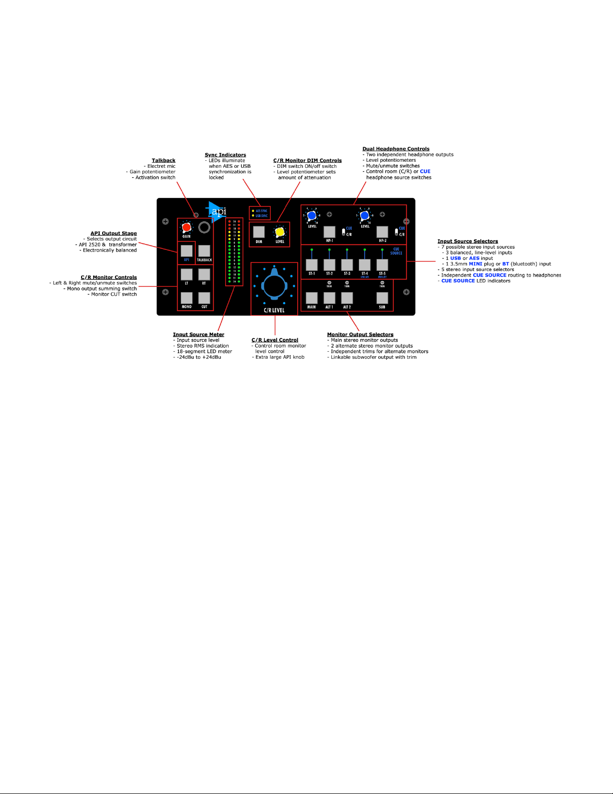
The MC531 is a comprehensive monitor controller that provides the following functions and features:
• Selectors for three sets of stereo monitors:
o MAIN
o ALT 1 (alternate 1) with trim
o ALT 2 (alternate 2) with trim
• Assignable subwoofer integration:
o Programmable link with the MAIN, ALT 1, and/or ALT 2
o SUB ON/off button and trim
• Seven total stereo input sources:
o Five stereo input source selectors
o Three analog balanced, line-level input sources (ST-1, ST-2, ST-3)
o Two digital input sources (ST-4)
§ AES
§ USB (no driver required)
§ Digital synchronization LED indicators
o Two consumer input sources (ST-5)
§ 3.5mm MINI Plug (front and rear)
§ Bluetooth (BT)
o High-resolution 18-segment LED input source meter
• Main output section:
o DIM function with level control
o Independent Left (LT) and Right (RT) mute buttons
o CUT (mute) button
o MONO summing button
o C/R LEVEL volume potentiometer with large API knob
o Selectable API 2520 op-amp/transformer or electronically balanced output stages
o XLR output connectors
MC531 Monitor Controller API
Page 6

3
• Two independent headphone outputs:
o ON/off button
o LEVEL potentiometer
o Choice of 2 sources:
§ Control Room (C/R) source
§ CUE source
• Talkback to headphones
o Talkback electret microphone
o Talkback GAIN
o TALKBACK activation button
The MC531 is built to the same exacting build standards as API consoles.
MC531 Monitor Controller API
Page 7
4
2.0 Input Source Selectors
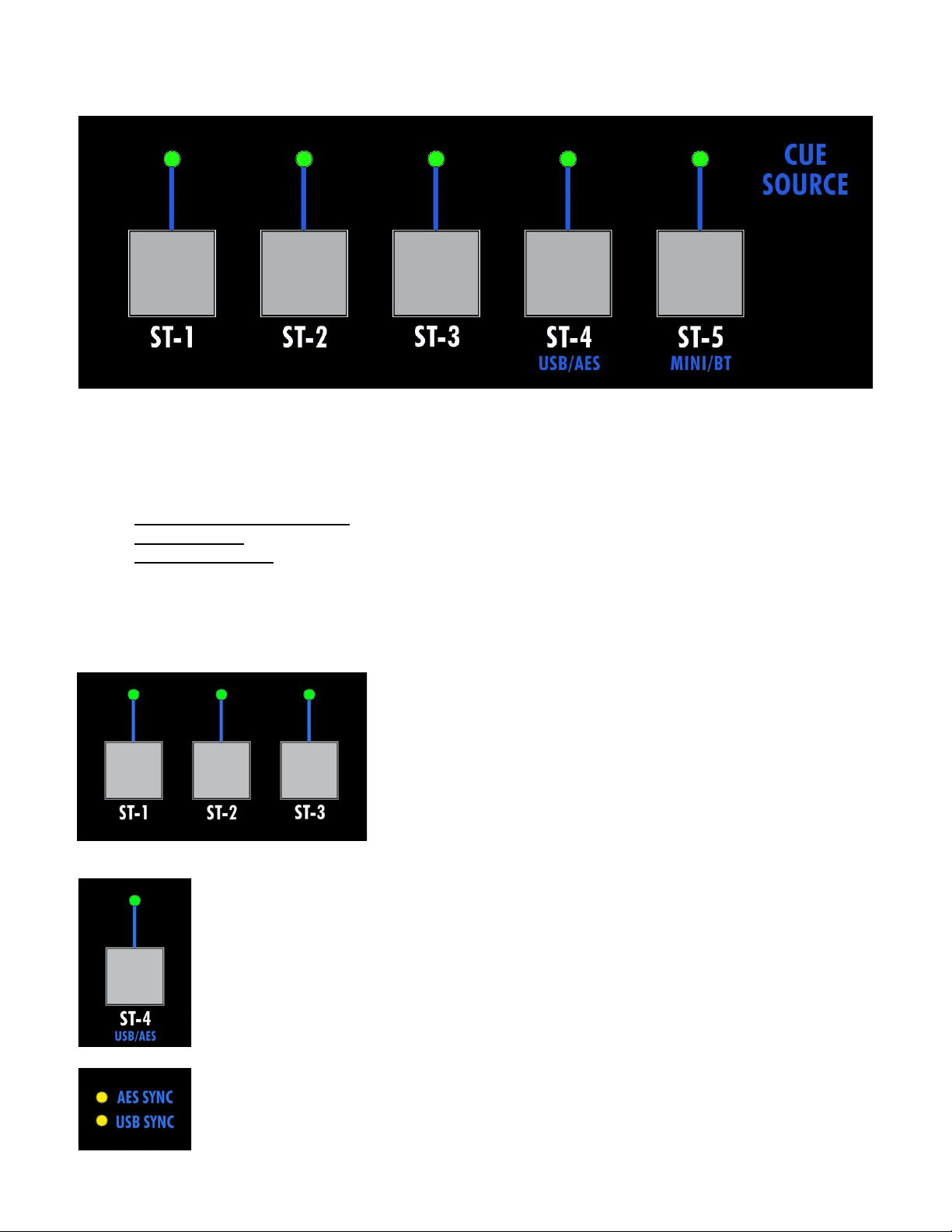
Five (5) input source selectors provide a choice of seven (7) different audio sources to feed the selected
set of monitors. Each input source is buffered with an API 2510 op-amp. Only one source can be
selected at a time.
The input source selectors are divided into three categories:
• Analog (ST-1, ST-2, ST-3)
• Digital (ST-4): USB or AES
• Consumer (ST-5): 3.5mm MINI plug or Bluetooth (BT)
2.1 Input Source Selection
The MC531 input source selectors function as follows:
To select an analog input source, press the desired ST-1, ST-
2, or ST-3 source selector button:
• Balanced, low-impedance, line-level
• ¼” TRS jack pairs on rear panel interface
• The active analog source button will illuminate
To select a digital USB or AES input source, press the ST-4 source selector button:
• After ST-4 is selected, press and hold to select between USB and AES inputs
o ST-4 will illuminate in blue when USB is selected as the active source
o ST-4 will illuminate in green when AES is selected as the active source
• Auto-sensing sample rate and bit depth
• Sample rates up to 192kHz
• No USB driver needed
• USB type-B USB rear panel interface
• 3-pin XLR AES rear panel interface
Yellow AES SYNC and USB SYNC LED indicators will illuminate when the MC531 is
locked to valid AES and/or USB digital input sources.
MC531 Monitor Controller API
Page 8
5
NOTE: The USB interface uses a USB type-B connector on the rear panel. The USB interface
relies on built-in drivers and is compatible with MAC OS and Windows10 or later.
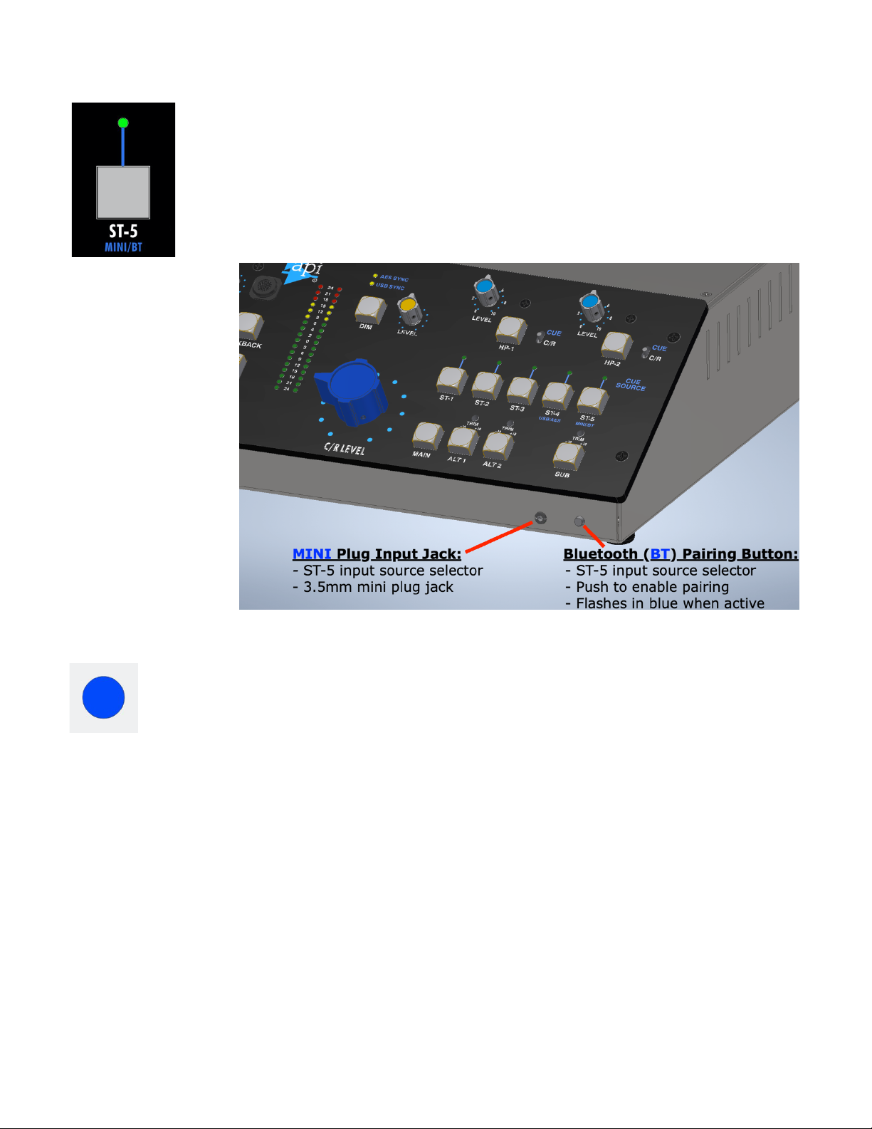
To select a consumer MINI plug or Bluetooth (BT) input source press the ST-5 source
selector button:
• After ST-5 is selected, press and hold to select between the MINI plug and
Bluetooth (BT) inputs
o ST-5 will illuminate in green when MINI is selected as the active source
o ST-5 will illuminate in blue when BT is selected as the active source
• 3.5mm MINI plug inputs on front and rear panels (Use only one at a time!)
The MINI plug input
jacks are located
below on the front of
the MC531 below the
control panel and as
well as on the rear of
the unit (not shown
here).
The Bluetooth (BT)
pairing button is also
located on the front
of the MC531 below
the control panel.
2.1.1 Bluetooth Pairing
To pair the MC531 with a Bluetooth audio source, perform the following steps:
1. Press the Bluetooth pairing button located below the control panel on the front of
the MC531.
a. The button will start flashing in blue.
b. If ST-5 is active and Bluetooth (BT) is selected and the monitors are on, a
pairing tone will be heard.
2. Enter the Bluetooth pairing mode on the device to be connected.
3. Select “API MC531” from the menu.
a. The device will connect to the MC531 and will indicate the connection.
b. The MC531 will produce another tone to confirm the pairing and the button
will stop flashing.
Once pairing has been established, audio from the Bluetooth device will be available as an input source
via the ST-5 input selector. Bluetooth (BT) must be selected as the active input source for ST-5.
NOTE: When using an Android device, select the MC531 option with the headset icon.
NOTE: The MC531 can connect to multiple Bluetooth devices at the same time, but only one
device can be heard at a time. The device that “play” was pressed on last will be the
device heard.
MC531 Monitor Controller API
Page 9
6
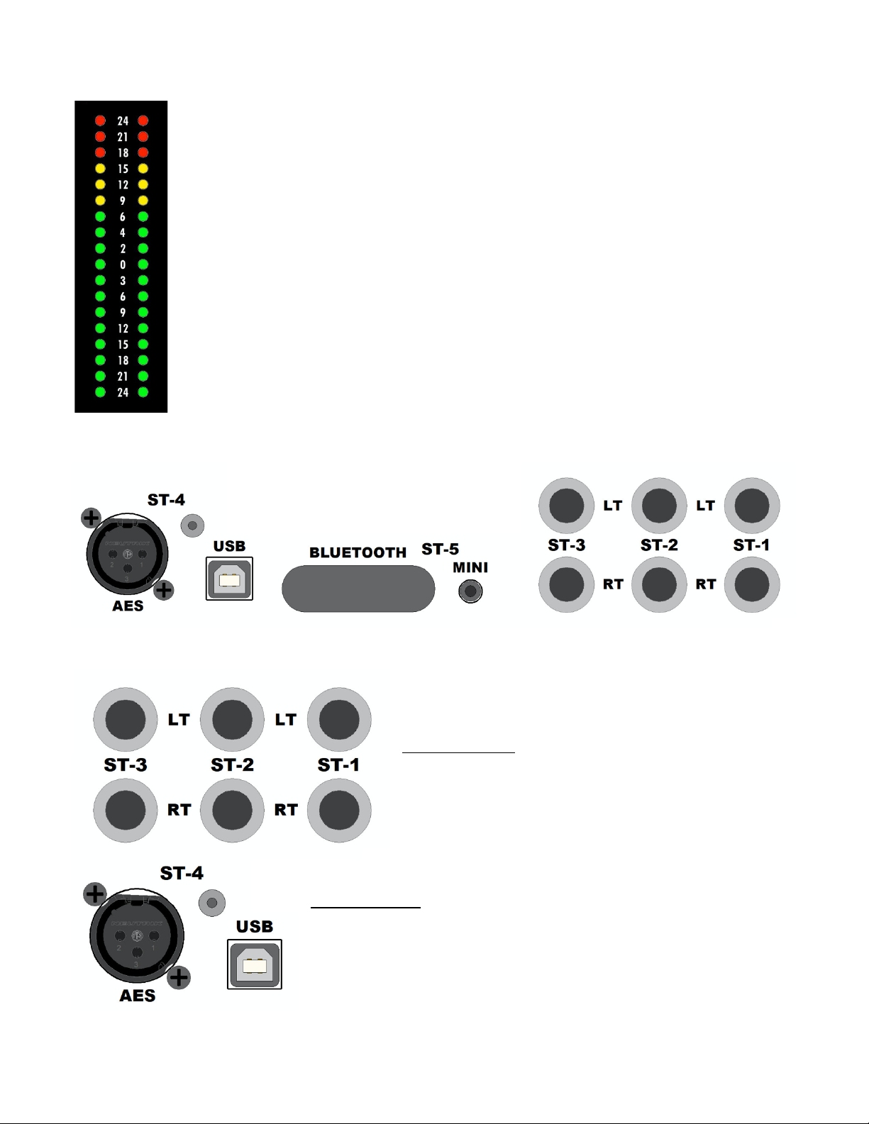
2.2 Input Source Meter
The level of the selected input source is displayed on a high-resolution RMS meter.
• -24dBu to +24dBu range
• 18-segment LED meter
NOTE: Stereo METER outputs connections are provided on the rear panel for
interfacing an external meter.
2.3 Input Source Connections
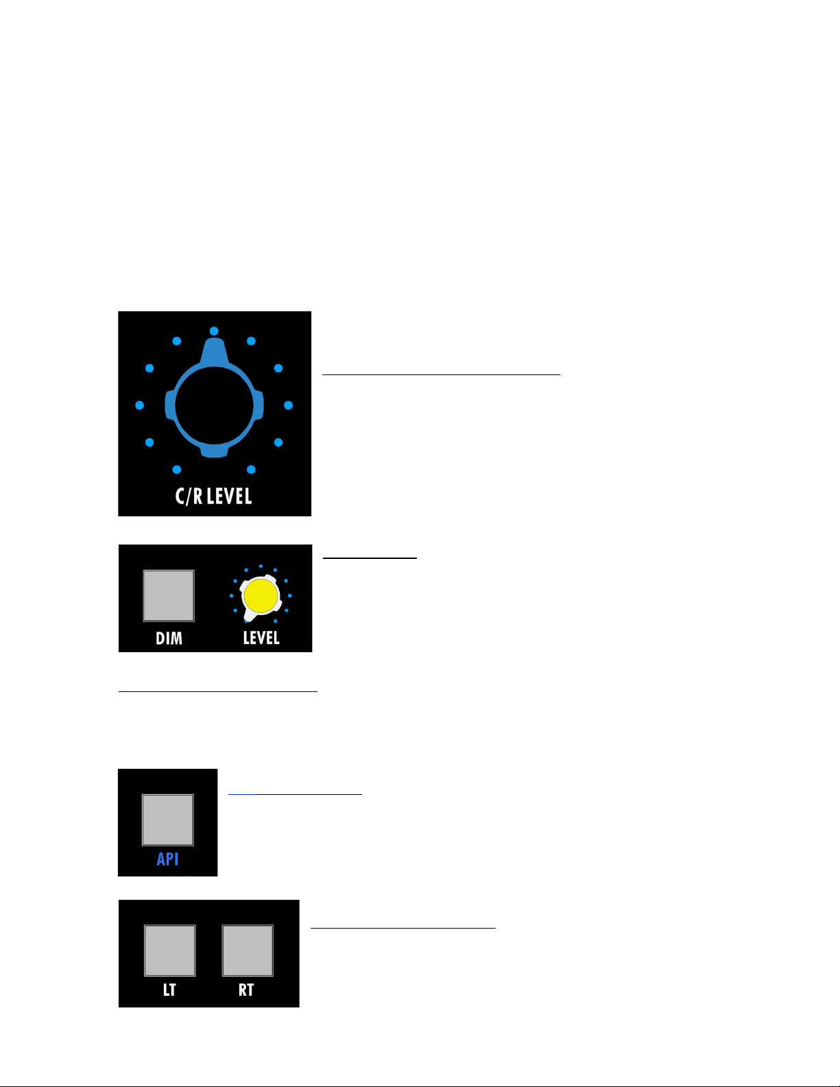
A complete set of input source connections are provided on the rear panel of the MC531. These
connections are as follows:
Analog Inputs: ST-1, ST-2, and ST-3
• LT and RT: Left and Right stereo pairs
• Balanced, low-impedance, line-level
• ¼” TRS jacks
Digital Inputs: ST-4
• AES: 3-pin female XLR, AES3 standard
• USB: USB type-B connector
NOTE: The USB interface uses a USB type-B connector on the rear panel. The USB interface
relies on built-in drivers and is compatible with MAC OS and Windows10 or later.
MC531 Monitor Controller API
Page 10

7
Consumer Inputs: ST-5
• BLUETOOTH: Bluetooth antenna
• MINI: 3.5mm stereo (TRS) jack for MINI plug
MC531 Monitor Controller API
Page 11
8
3.0 Monitor Control Functions
The MC531 provides a comprehensive suite of monitor functions and controls.
• C/R LEVEL volume potentiometer
• DIM level and activation button
• Selectable API 2520 op-amp/transformer or electronically balanced output stage
• MONO summing button
• LT and RT mute buttons
• CUT (mute) button
3.1 Monitor Controls
The MC531 monitor controls function as follows:
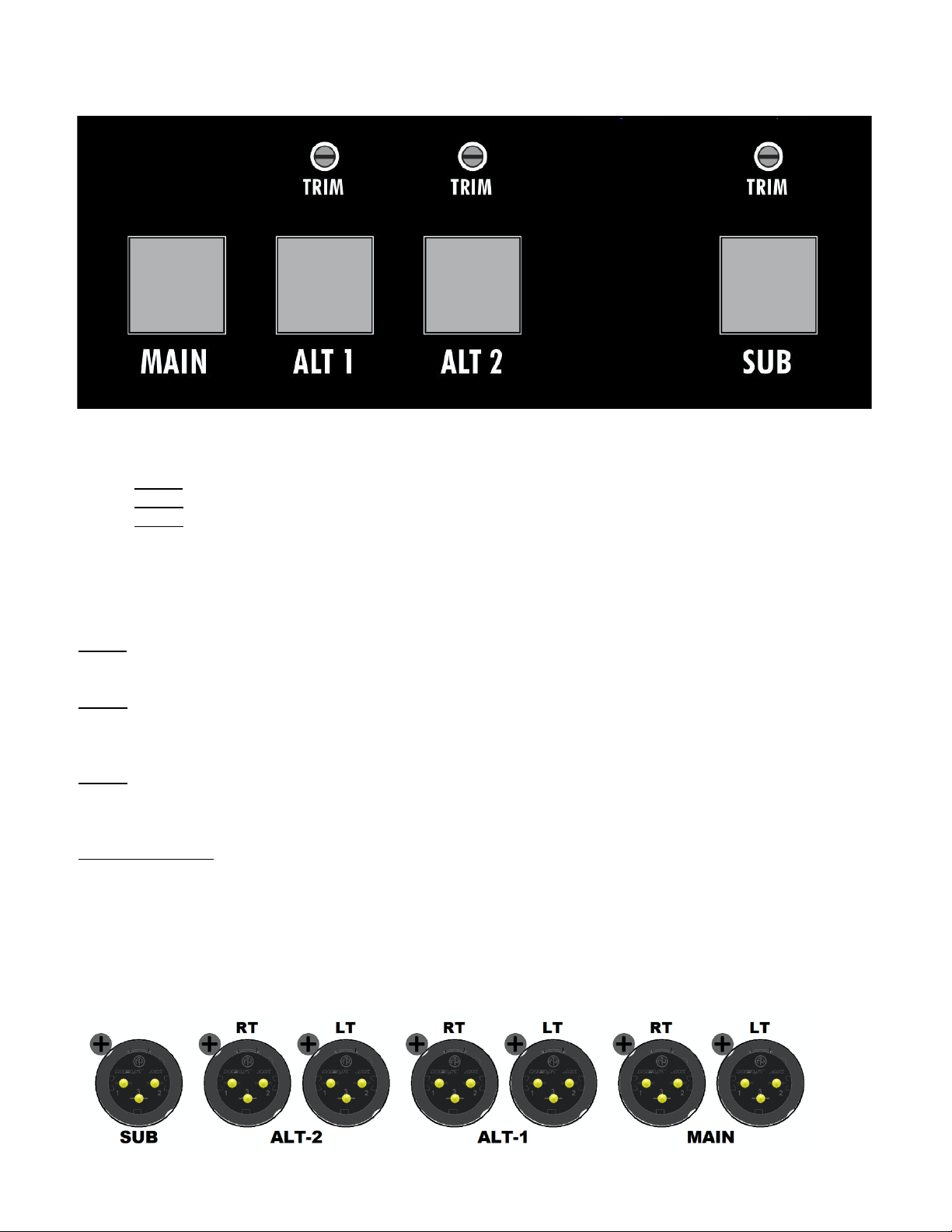
C/R LEVEL (Control Room Level): Controls the output level for
the selected monitor system.
• Volume control for the selected monitor system
• The largest and most dangerous knob on the unit…
Please use it wisely!
DIM (button): Reduces the output level of the selected monitors
by routing the selected monitor source through the DIM LEVEL
attenuation potentiometer.
• The amount of level reduction is set by the DIM LEVEL pot
• DIM is automatically engaged when the TALKBACK button
is engaged
• Illuminates in yellow when engaged
DIM LEVEL (potentiometer): Sets the amount of attenuation applied to the selected monitor
outputs when the DIM button is engaged.
• Only active when the DIM button is engaged
• 0dB to -¥dB range
API (output stage): Routes monitor outputs through an API 2520 and custom
transformer output stage when engaged
• Electronically balanced output stage when not engaged
• Illuminates in blue when engaged
LT and RT (Left and Right): Cuts the Left and/or Right feeds to the
selected monitor system.
• ON/off (mute/unmute) switch for the selected monitor
outputs
• Illuminates in red when engaged
MC531 Monitor Controller API
Page 12

9
MONO: Sums the Left & Right monitor output feed to mono.
CUT (mute): Cuts the feed to the selected monitor system.
• Illuminates in red when engaged
• ON/off (mute/unmute) switch for the selected monitor outputs
• Illuminates in red when engaged
MC531 Monitor Controller API
Page 13
10
4.0 Monitor Selectors
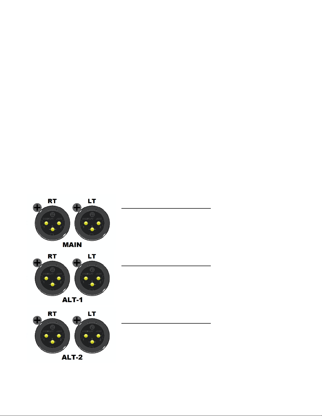
The MC531 supports three (3) sets of stereo audio monitors, plus a subwoofer with a programmable
link to each stereo pair. Only one set of monitors can be selected at a time.
• MAIN: Main control room monitors
• ALT 1: Mid-field or near-field control room monitors
• ALT 2: Mid-field or near-field control room monitors
4.1 Monitor Selector Controls
The MC531 monitor selectors function as follows:
MAIN: Routes the selected input source to the MAIN monitor XLR outputs on the rear panel.
• Illuminates in blue when engaged
ALT 1: Routes the selected input source to the ALT 1 monitor XLR outputs on the rear panel.
• A -12dB to +6dB trim-pot sets the ALT 1 output level for matching with main system
• Illuminates in blue when engaged
ALT 2: Routes the selected input source to the ALT 2 monitor XLR outputs on the rear panel.
• A -12dB to +6dB trim-pot sets the ALT 2 output level for matching with main system
• Illuminates in blue when engaged
SUB (subwoofer): ON/off button for the subwoofer output
• Mono, unfiltered sum of selected Left and Right monitor outputs*
• Programmable link with MAIN, ALT 1, and ALT 2 monitor selections
• A -12dB to +6dB trim-pot sets the SUB output level for matching with active set of
monitors
• If both LT and RT are engaged or if CUT is engaged, the SUB output is also muted
• Illuminates in blue when engaged
MC531 Monitor Controller API
Page 14
11
*IMPORTANT NOTE: The MC531 does not provide any bass management functions. When
engaged, the SUB (subwoofer) output is unfiltered, full-bandwidth mono
sum of the left and right monitor outputs. While this output is intended
to feed a subwoofer, appropriate external filtration is needed for proper
use (not supplied).
4.2 Subwoofer Output Linking
Activation of the SUB (subwoofer) output can be linked to the MAIN, ALT 1, and/or ALT 2 monitor
selectors so it will automatically activate when linked sets of monitors are selected.
To link the SUB (subwoofer) output with a set of monitors, perform the following steps:
1. Press and hold the monitor selector (MAIN, ALT 1, or ALT 2) to be linked with the
subwoofer.
a. The monitor selector will turn green
2. If the SUB button is green the link is established, press the SUB button to break the link.
3. If the SUB button is not illuminated in green, press the SUB button to establish the link.
Once the link has been established, the SUB (subwoofer) output will be activated when the linked set
of monitor is selected.
4.3 Monitor Output Connections
A complete set of stereo monitor output connections are provided on the rear panel of the MC531.
These connections are as follows:
MAIN LEFT & RIGHT OUTPUTS:
• LT and RT: Left and Right stereo pair
• Balanced, low-impedance, line-level
• 3-pin male XLRs
• Pin 1 = Ground, Pin 2 = +, Pin 3 = -
ALT 1 LEFT & RIGHT OUTPUTS:
• LT and RT: Left and Right stereo pair
• Balanced, low-impedance, line-level
• 3-pin male XLRs
• Pin 1 = Ground, Pin 2 = +, Pin 3 = -
ALT 2 LEFT & RIGHT OUTPUTS:
• LT and RT: Left and Right
• Balanced, low-impedance, line-level
• 3-pin male XLRs
• Pin 1 = Ground, Pin 2 = +, Pin 3 = -
MC531 Monitor Controller API
Page 15
12
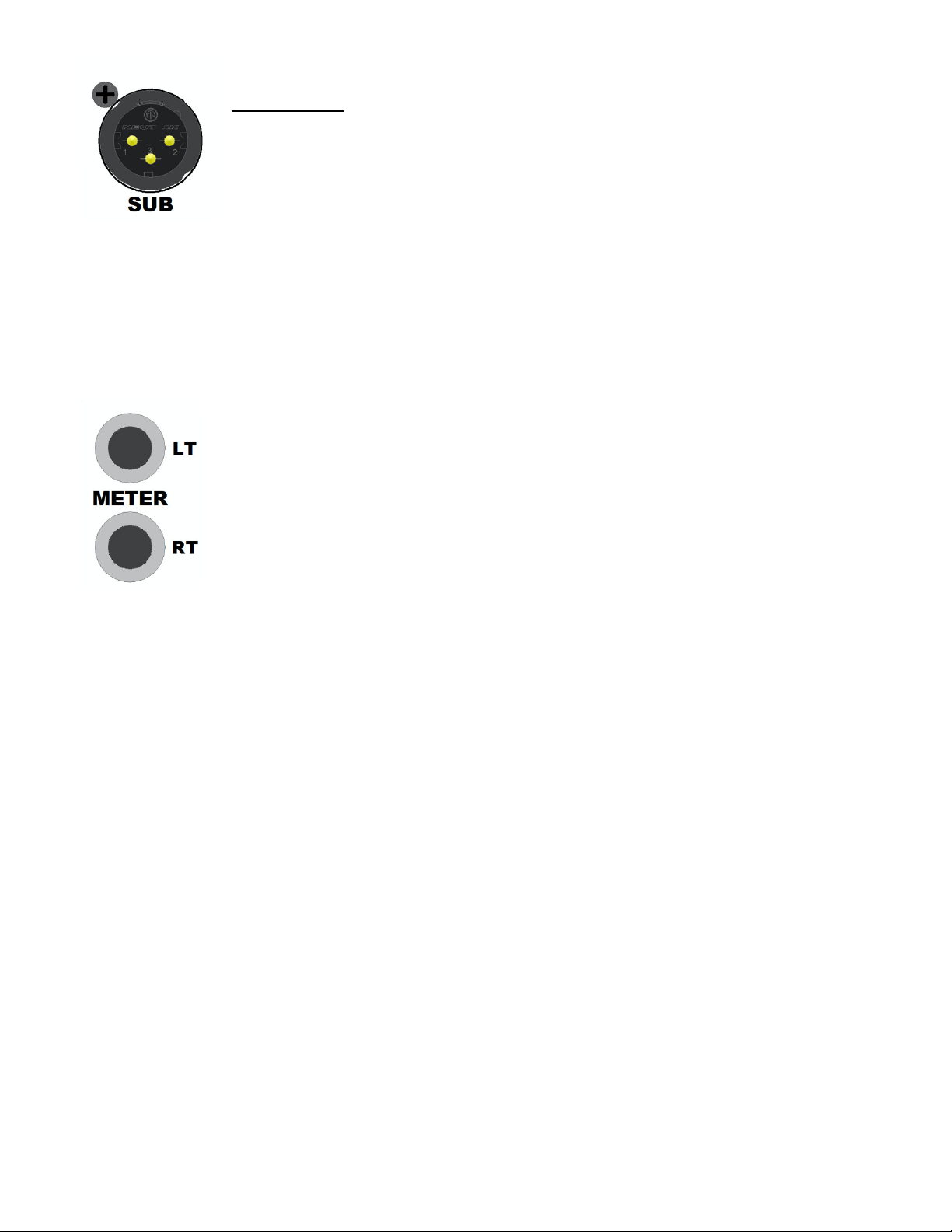
SUB OUTPUT: Mono, unfiltered sum of selected Left and Right monitor outputs*
• Balanced, low-impedance, line-level
• 3-pin male XLR
• Pin 1 = Ground, Pin 2 = +, Pin 3 = -
*IMPORTANT NOTE: The MC531 does not provide any bass management functions. When
engaged, the SUB (subwoofer) output is unfiltered, full-bandwidth mono
sum of the left and right monitor outputs. While this output is intended
to feed a subwoofer, appropriate external filtration is needed for proper
use (not supplied).
4.4 External Meter Connections
The signal of the selected input source that is displayed on the high-resolution RMS
meter is also available for use with external metering systems via the METER
outputs.
• Unity gain selected input signal
• LT and RT: Left and Right stereo pair
• Balanced, low-impedance, line-level
• ¼” TRS jacks
MC531 Monitor Controller API
Page 16
13
5.0 Headphone Amplifiers
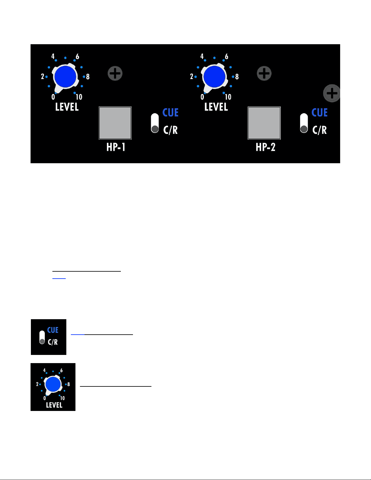
The MC531 is equipped with two independent stereo headphone amplifiers, HP-1 and HP-2. The
amplifier circuit is the same as found in API consoles such as THE BOX, 1608, 1608-II, and 2448.
The MC531 headphone amplifiers are designed for use by the engineer, musicians, and others in the
control room. Each headphone amplifier has the following features:
• ON/off switch
• Stereo volume potentiometer
• ¼” stereo headphone jack (located on rear panel)
• Source selector: Control room (C/R) or CUE
• Not affected by the control room CUT or monitor output selectors
• Talkback to headphones
The headphone amplifiers can be fed from two (2) primary sources, plus talkback when activated:
• Control Room (C/R): Same feed as the monitor outputs
• CUE: Assignable input source
5.1 Headphone Controls
The MC531 headphone amplifier controls function as follows:
CUE – C/R (switch): Selects the source for the headphone amplifier.
LEVEL (potentiometer): Level control for the headphone amplifier.
MC531 Monitor Controller API
Page 17
14
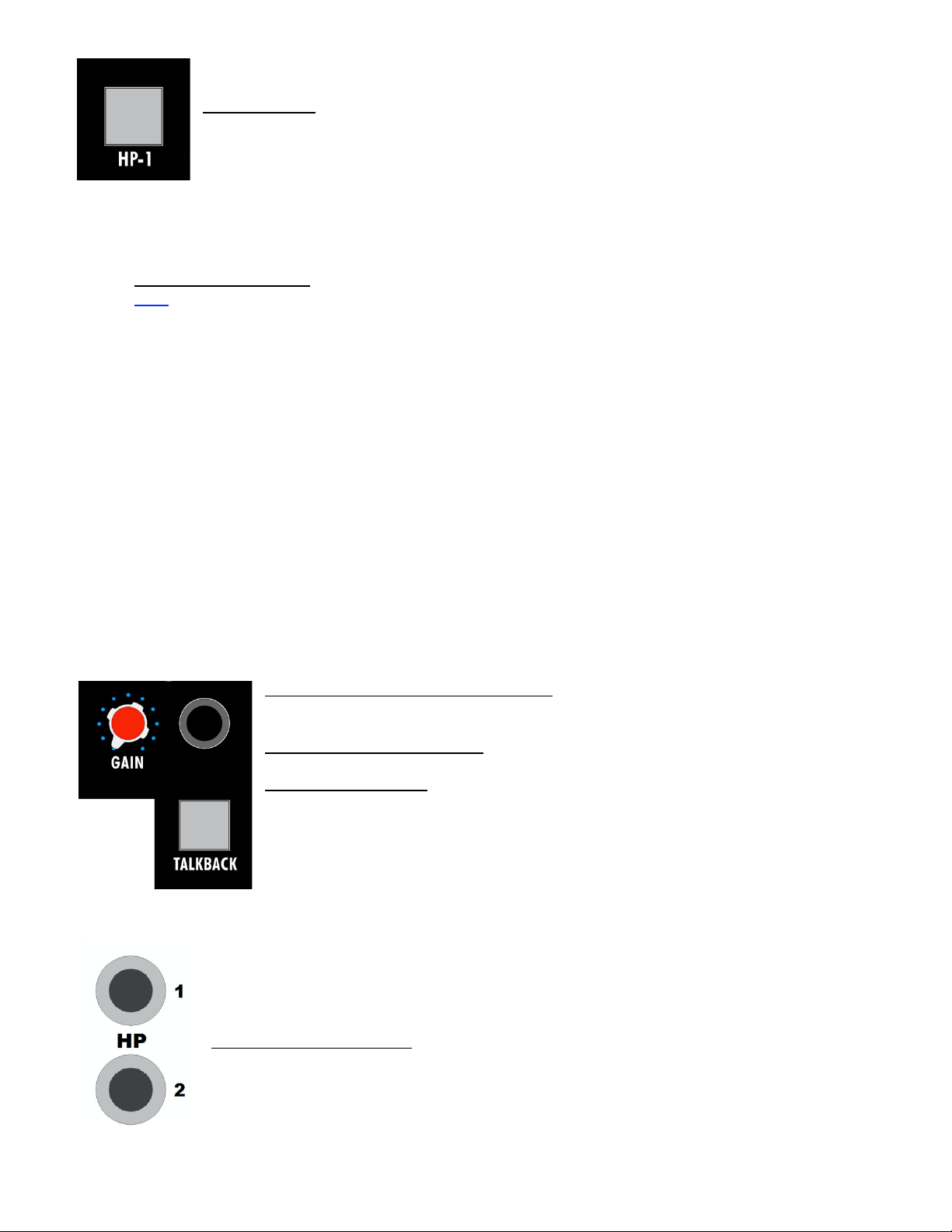
HP-1 or HP-2: ON/off switch for the headphone amplifiers.
• Illuminates in green when engaged
5.2 Headphone Cue Function
The headphone amplifiers can be fed from two (2) primary sources, plus talkback when activated:
• Control Room (C/R): Same feed as the monitor outputs
• CUE: Assignable input source
Any input source can be assign to the CUE feed. Only one input source can be assigned as the CUE
SOURCE. To assign an input source as the CUE SOURCE, perform the following steps:
1. Press and hold either the HP-1 or HP-2 buttons.
a. The HP-1 or HP-2 buttons will both “shimmer” quickly
2. While continuing to press a HP button, press an input source button to select it as the CUE
SOURCE.
a. The green LED above the input source selector will illuminate indicating it has been
assigned as the CUE SOURCE.
3. Release the HP button and the CUE SOURCE will be set.
4. Set the CUE-C/R switch to CUE to route the CUE SOURCE to either headphone amplifier.
The CUE SOURCE for ST-4 and ST-5 will follow the selected input for these sources (USB or AES, MINI or BT).
5.3 Talkback to Headphones
The MC531 is equipped with a talkback mic that can be added to the selected source for the headphone
amplifiers.
TALKBACK GAIN (potentiometer): Volume control for talkback to the
headphone amplifiers
TALKBACK MICROPHONE: Electret condenser microphone
TALKBACK (button): Talkback activation button
• Adds the talkback mic to the selected source for the headphone
amplifiers
• Momentary button (press and hold to use)
• Automatically engages the DIM function when engaged
• Illuminates in red when engaged
5.4 Headphone Connections
HP 1 and 2 (headphone): Stereo headphone amplifier output
• ¼” stereo TRS jacks
MC531 Monitor Controller API
Page 18
15
6.0 Rear Panel
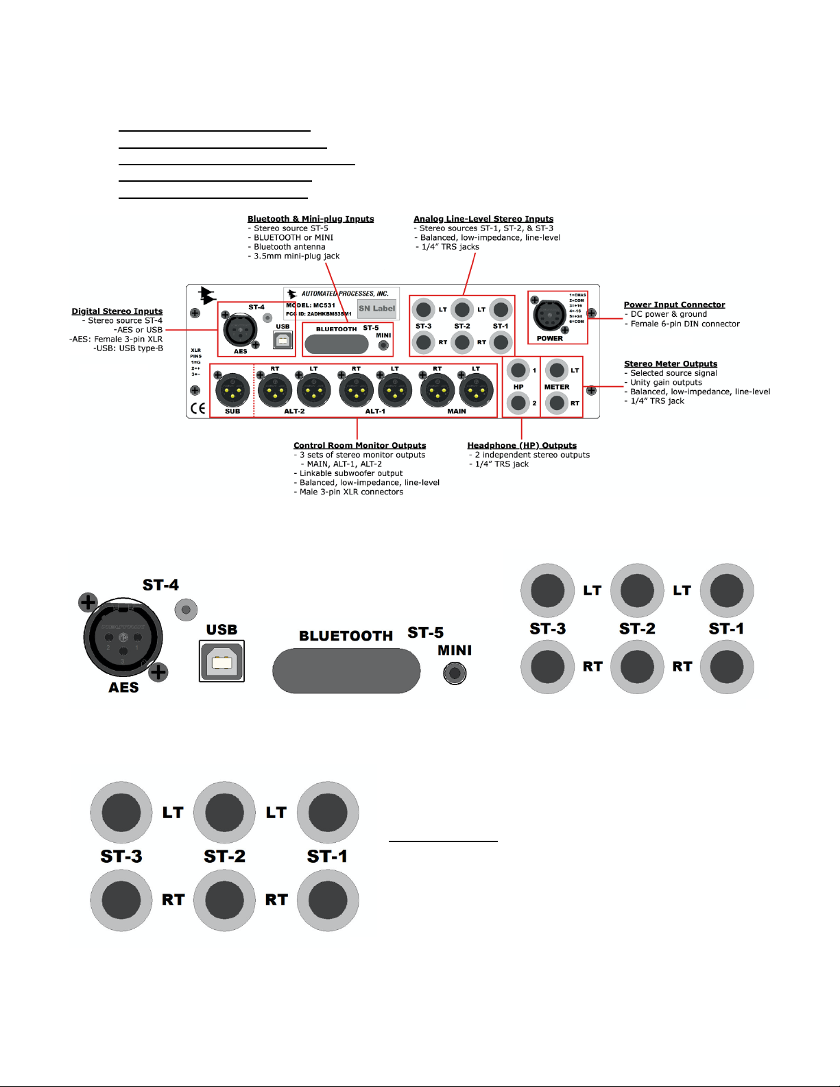
The rear panel of the MC531 provide a complete set of connections including:
• Input Source Connectors: Analog (LT and RT), digital, and consumer
• Monitor Output Connectors: MAIN, ALT 1, ALT 2 (LT and RT)
• Headphone Output Connectors: HP-1, HP-2
• Meter Output Connectors: External meter LT and RT
• Power Supply Connector: DC power source and grounding
6.1 Input Source Connections
A complete set of input source connections are provided on the rear panel of the MC531. These
connections are as follows:
Analog Inputs: ST-1, ST-2, and ST-3
• LT and RT: Left and Right stereo pairs
• Balanced, low-impedance, line-level
• ¼” TRS jacks
MC531 Monitor Controller API
Page 19
16
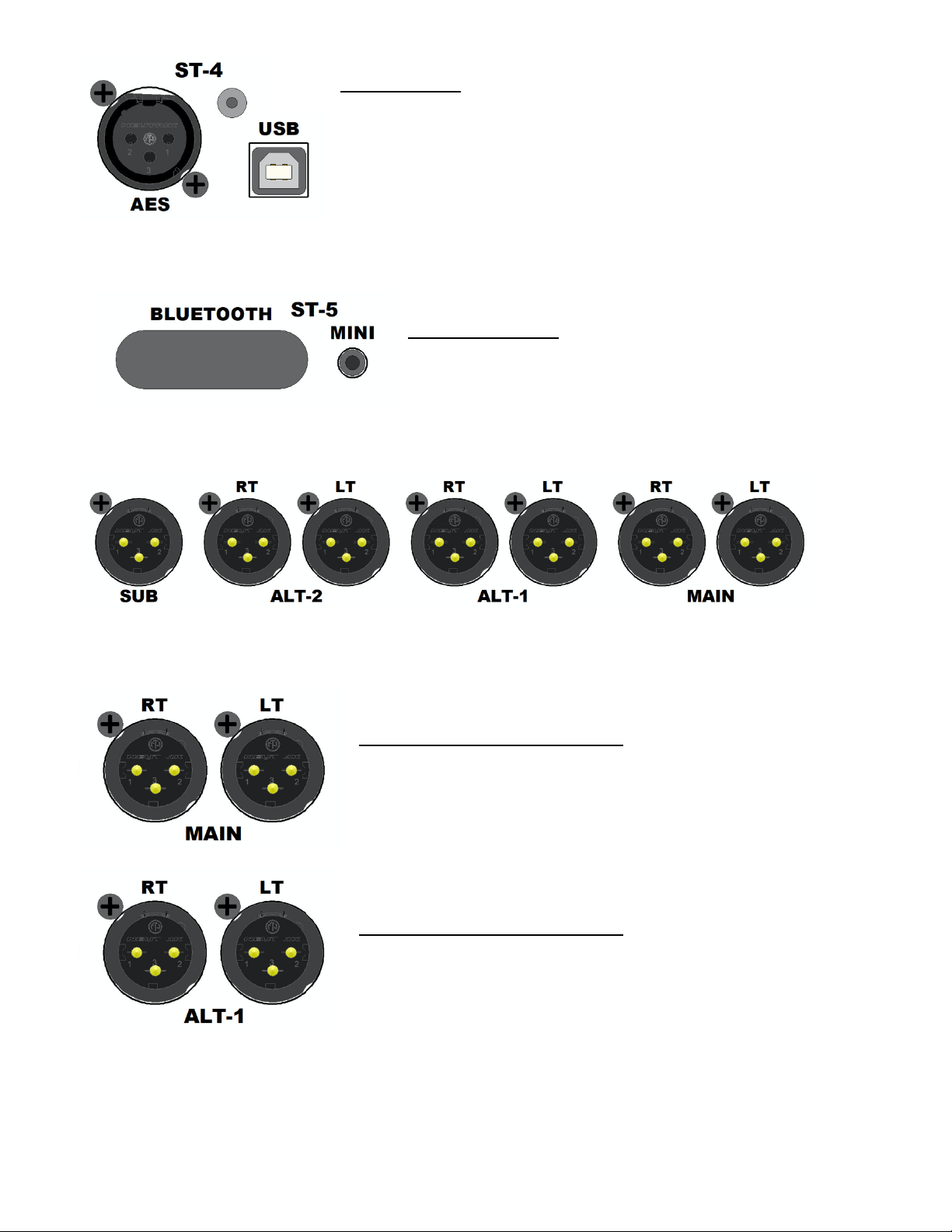
Digital Inputs: ST-4
• AES: 3-pin female XLR, AES3 standard
• USB: USB type-B connector
NOTE: The USB interface uses a USB type-B connector on the rear panel. The USB interface
relies on built-in drivers and is compatible with MAC OS and Windows10 or later.
Consumer Inputs: ST-5
• BLUETOOTH: Bluetooth antenna
• MINI: 3.5mm stereo (TRS) jack for MINI plug
6.2 Monitor Output Connections
A complete set of stereo monitor output connections are provided on the rear panel of the MC531.
These connections are as follows:
MAIN LEFT & RIGHT OUTPUTS:
• LT and RT: Left and Right stereo pair
• Balanced, low-impedance, line-level
• 3-pin male XLRs
• Pin 1 = Ground, Pin 2 = +, Pin 3 = -
ALT 1 LEFT & RIGHT OUTPUTS:
• LT and RT: Left and Right stereo pair
• Balanced, low-impedance, line-level
• 3-pin male XLRs
• Pin 1 = Ground, Pin 2 = +, Pin 3 = -
MC531 Monitor Controller API
Page 20
17
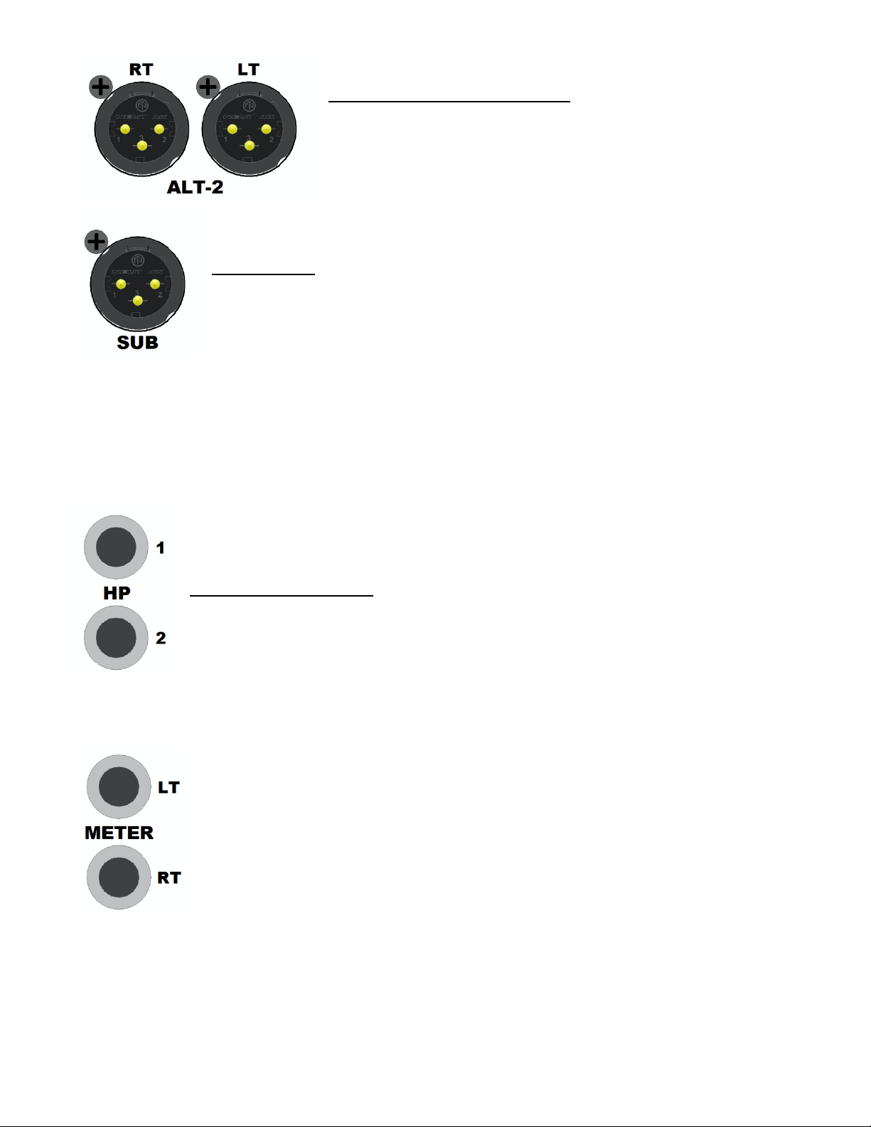
ALT 2 LEFT & RIGHT OUTPUTS:
• LT and RT: Left and Right stereo pair
• Balanced, low-impedance, line-level
• 3-pin male XLRs
• Pin 1 = Ground, Pin 2 = +, Pin 3 = -
SUB OUTPUT: Mono, unfiltered sum of selected Left and Right monitor outputs*
• Balanced, low-impedance, line-level
• 3-pin male XLR
• Pin 1 = Ground, Pin 2 = +, Pin 3 = -
*IMPORTANT NOTE: The MC531 does not provide any bass management functions. When
engaged, the SUB (subwoofer) output is unfiltered, full-bandwidth mono
sum of the left and right monitor outputs. While this output is intended
to feed a subwoofer, appropriate external filtration is needed for proper
use (not supplied).
6.3 Headphone Connections
HP 1 and 2 (headphone): Stereo headphone amplifier output
• ¼” stereo TRS jacks
6.4 External Meter Connections
The signal of the selected input source that is displayed on the high-resolution RMS
meter is also available for use with external metering systems via the METER
outputs.
• Unity gain selected input signal
• LT and RT: Left and Right stereo pair
• Balanced, low-impedance, line-level
• ¼” TRS jacks
MC531 Monitor Controller API
Page 21

18
6.5 Power Supply Connection
The MC531 is powered by an external DC power supply unit.
POWER: The main DC power supply unit connection is interfaced with a
single, locking, 6-pin female DIN connector.
MC531 Monitor Controller API
Page 22

19
APPENDIX
A1 MC531 Block Diagram
A2 Bluetooth Compatibility
A3 API Limited Warranty and Service
MC531 Monitor Controller API
Page 23
20
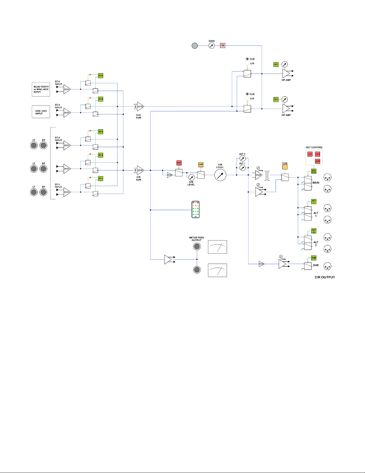
A1 MC531 Block Diagram
MC531 Monitor Controller API
Page 24

21
MSIP-R-R-API-MC531
A2 Bluetooth Compliance
ID: 2ADHKBM83SM1
This equipment has been tested and found to comply with the limits for a Class B digital device,
pursuant to part 15 of the FCC Rules. These limits are designed to provide reasonable protection
against harmful interference in a residential installation. This equipment generates, uses and can
radiate radio frequency energy, and if not installed and used in accordance with the instructions, may
cause harmful interference to radio communications. However, there is no guarantee that interference
will not occur in a particular installation. If this equipment does cause harmful interference to radio or
television reception, which can be determined by turning the equipment off and on, the user is
encouraged to try to correct the interference by one or more of the following measures:
• Reorient or relocate the receiving antenna
• Increase the separation between the equipment and receiver
• Connect the equipment into an outlet on a circuit different from that to which the receiver is
connected
• Consult the dealer or an experienced radio/TV technician for help
해당 _무선설비는 _운용중 _전파혼신 _가능성이 _있음
MC531 Monitor Controller API
Page 25

22
A3 API Limited Warranty and Service
a. Warranty Information: This product carries a one year labor and a five year parts warranty
from date of purchase. API (Automated Processes, Incorporated) does not cover claims for
damage due to alteration and/or abuse. This warranty is limited to failures during normal use,
which are due to defects in material or workmanship. If any defects are found in the materials
or workmanship, or if the product fails to function properly during the applicable warranty period,
API, at its option, will repair or replace the product.
b. PLEASE NOTE: The design or quality of any non-authorized third party service or vendor is
beyond the control of API. Accordingly service or modification of any API unit except by an
authorized API representative may VOID this warranty.
c. API reserves the right to inspect any products that may be the subject of any warranty claims
before repair or replacement is carried out. Final determination of warranty coverage lies solely
with API.
d. This warranty is extended to the original purchaser and to anyone who may subsequently
purchase this product within the applicable warranty period. Proof of purchase may be required.
e. For questions regarding operation, interfacing or service of your API product, please contact
your API dealer from whom you purchased the unit. Many times your authorized API dealer is
the fastest and most cost-effective way to maintain and service your product.
f. You may also contact API’s Service Department directly.
a. Call API at 301-776-7879 (ext. 252) between 8:30 AM and 5:00 PM Monday through
Friday (Eastern Time) to get a Return Authorization (RA). Products returned without an
RA number may not be accepted.
b. Pack the defective part by wrapping in plastic and cushioning material. Seal securely in
an approved shipping container. If you do not have a sufficient shipping container, ask
API for advice when calling for the RA number.
c. Include a note explaining the problem and conditions of the service request. Include
your complete return address (no P.O. Boxes, please).
d. Ship the product freight prepaid to:
API
8301 Patuxent Range Road
Jessup, MD 20794
IMPORTANT: Be sure the RA number is plainly written on the shipping carton.
g. This is your sole warranty. API does not authorize any third party, including any dealer or sales
representative, to assume liability on behalf of API or to make any warranty for API.
h. THE WARRANTY GIVEN ON THIS PAGE IS THE SOLE WARRANTY GIVEN BY API AND IS IN LIEU
OF ALL OTHER WARRANTIES, EXPRESS AND IMPLIED, INCLUDING THE WARRANTIES OF
MERCHANTABILITY AND FITNESS FOR A PARTICULAR PURPOSE. THE WARRANTY GIVEN ON
THIS PAGE SHALL BE STRICTLY LIMITED IN DURATION TO FIVE (5) YEARS FROM THE DATE OF
THE ORIGINAL PURCHASE FROM API OR AN AUTHORIZED API DEALER. UPON EXPIRATION OF
THE APPLICABLE WARRANTY PERIOD API SHALL HAVE NO FURTHER WARRANTY OBLIGATION
OF ANY KIND. API SHALL NOT BE LIABLE FOR ANY INCIDENTAL, SPECIAL, OR CONSEQUENTIAL
DAMAGES THAT MAY RESULT FROM ANY DEFECT IN THE API PRODUCT OR ANY WARRANTY
CLAIM.
This warranty provides specific legal rights and you may have other rights, which vary from state to
state.
MC531 Monitor Controller API
Page 26

8301 Patuxent Range Road
Jessup, MD 20794 USA
301-776-7879
http://www.apiaudio.com
 Loading...