

Page 1

PRODUCTS
AUT OMATION
Operator’s Manual
GROUP, INC.
VBL Series
General Purpose
Vibrating Level Sensor
Rev. A2, 9/09
Automation Products Group, Inc.
APG...Providing tailored solutions for measurement applications
T el: 1/888/525-7300 • Fax: 1/435/753-7490 • www.apgsensors.com • E-mail: sales@apgsensors.com
Page 2

VBL Series Rev. A2, 9/09
T able of Content s
Warranty ......................................................................................... 3
Introduction .................................................................................... 4
Specifications.................................................................................. 5
Dimensions...................................................................................... 7
Nomenclature.................................................................................. 8
Electronics ...................................................................................... 9
Principle of Operation .................................................................. 10
Installation .................................................................................... 11
Adjustment Procedure .................................................................. 14
Sensitivity...................................................................................... 16
Wiring............................................................................................ 17
Start Up ........................................................................................ 17
Maintenance ................................................................................. 18
Troubleshooting ............................................................................ 20
Automation Products Group, Inc.
APG...Providing tailored solutions for measurement applications
2
T el: 1/888/525-7300 • Fax: 1/435/753-7490 • www.apgsensors.com • sales@apgsensors.com
Page 3

Rev. A2, 9/09 VBL Series
• Warranty and Warranty Restrictions
APG warrants its products to be free from defects of material and workmanship
and will, without charge, replace or repair any equipment found defective upon
inspection at its factory, provided the equipment has been returned,
transportation prepaid, within 24 months from date of shipment from factory .
THE FOREGOING WARRANTY IS IN LIEU OF AND EXCLUDES ALL OTHER
W ARRANTIES NOT EXPRESSLY SET FOR TH HEREIN, WHETHER
EXPRESSED OR IMPLIED BY OPERATION OF LAW OR OTHER WISE
INCLUDING BUT NOT LIMITED TO ANY IMPLIED WARRANTIES OF
MERCHANT ABILITY OR FITNESS FOR A P AR TICULAR PURPOSE.
No representation or warranty , express or implied, made by any sales
representative, distributor, or other agent or representative of APG which is not
specifically set forth herein shall be binding upon APG. APG shall not be liable
for any incidental or consequential damages, losses or expenses directly or
indirectly arising from the sale, handling, improper application or use of the
goods or from any other cause relating thereto and APG’s liability hereunder, in
any case, is expressly limited to the repair or replacement (at APG’ s option) of
goods.
Warranty is specifically at the factory. Any on site service will be provided at
the sole expense of the Purchaser at standard field service rates.
All associated equipment must be protected by properly rated electronic/
electrical protection devices. APG shall not be liable for any damage due to
improper engineering or installation by the purchaser or third parties. Proper
installation, operation and maintenance of the product becomes the
responsibility of the user upon receipt of the product.
Returns and allowances must be authorized by APG in advance. APG will
assign a Return Material Authorization (RMA) number which must appear on
all related papers and the outside of the shipping carton. All returns are subject
to the final review by AP G. Returns are subject to restocking charges as
determined by APG’ s “Credit Return Policy”.
Automation Products Group, Inc.
APG...Providing tailored solutions for measurement applications
T el: 1/888/525-7300 • Fax: 1/435/753-7490 • www.apgsensors.com • sales@apgsensors.com
3
Page 4

VBL Series Rev. A2, 9/09
• Introduction
The vibrating level sensor, VBL-12, VBL-22, and VBL-32 are made specifically
for solid level measurement in containers. It is designed for minimum density of
bulk solid (loose) 12 lbs. per cubic feet (0.2 g/cm3). Not only fine powders,
ordinary powder, granular materials and pellets, but also for detecting sediments
in the liquids such as sludge, sand, etc. The model VBL is usable in a wide range
of specifications. Since the detecting point is at the tip of the vibration pipe, it is
immune to buildup of the medium on the inside wall of the vessel.
Automation Products Group, Inc.
APG...Providing tailored solutions for measurement applications
4
T el: 1/888/525-7300 • Fax: 1/435/753-7490 • www.apgsensors.com • sales@apgsensors.com
Page 5

Rev. A2, 9/09 VBL Series
• Specifications
Operational Versions
VBL-12: Compact
VBL-22: For extended probes
VBL-32: For flexible extension
Performance
3
Bulk Density: Min 0.2 g/cm
sensitivity
Output Contact Rating: 1 SPDT , 240 V 3A AC, 30 V 3 A DC (resistive)
Vibration Frequency: Approximately 330 Hz
Sensitivity Adjustments
Very High for highly fluidized powders
High for fine powders (bulk density 0.2-0.5 g/cm
3
)
Standard for bulk density 0.5 g/cm3 or more (factory setting)
Low for sticky media
Loss of Power Mode: Provided (high or low) by switch
Detection Time Delay (optional field adjustable)
Covered: 1 sec.
Free: 5 sec.
Indication:
Green LED for Power status
Red LED for Relay status
Electrical
Supply V oltage: 90 to 132 VAC, 180 to 264 VAC or 24 VDC
Power Consumption: Approximately 5 VA
Physical
Material
Housing: Aluminum die cast (ADC)
Vibration Probe: 304SS (316SS optional)
Cable Entries: G 3/4, G 1/2 or NPT 1/2
Rating: IP65/NEMA 4
Automation Products Group, Inc.
APG...Providing tailored solutions for measurement applications
T el: 1/888/525-7300 • Fax: 1/435/753-7490 • www.apgsensors.com • sales@apgsensors.com
5
Page 6

VBL Series Rev. A2, 9/09
Environmental
Operating T emperatur e:
Vibration Rod Housing
VBL-12, 22 -4 to 300°F -4 to 140°F
(-20 to 150°C) (-20 to 60°C)
VBL-31 -4 to 158°F -4 to 140°F
(-20 to 70°C) (-20 to 60°C)
Maximum Pressure: 290 psi (20 bar)
Automation Products Group, Inc.
APG...Providing tailored solutions for measurement applications
6
T el: 1/888/525-7300 • Fax: 1/435/753-7490 • www.apgsensors.com • sales@apgsensors.com
Page 7
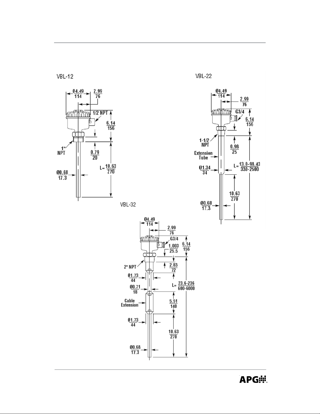
Rev. A2, 9/09 VBL Series
Dimensions — in./mm
Automation Products Group, Inc.
APG...Providing tailored solutions for measurement applications
T el: 1/888/525-7300 • Fax: 1/435/753-7490 • www.apgsensors.com • sales@apgsensors.com
7
Page 8
VBL Series Rev. A2, 9/09
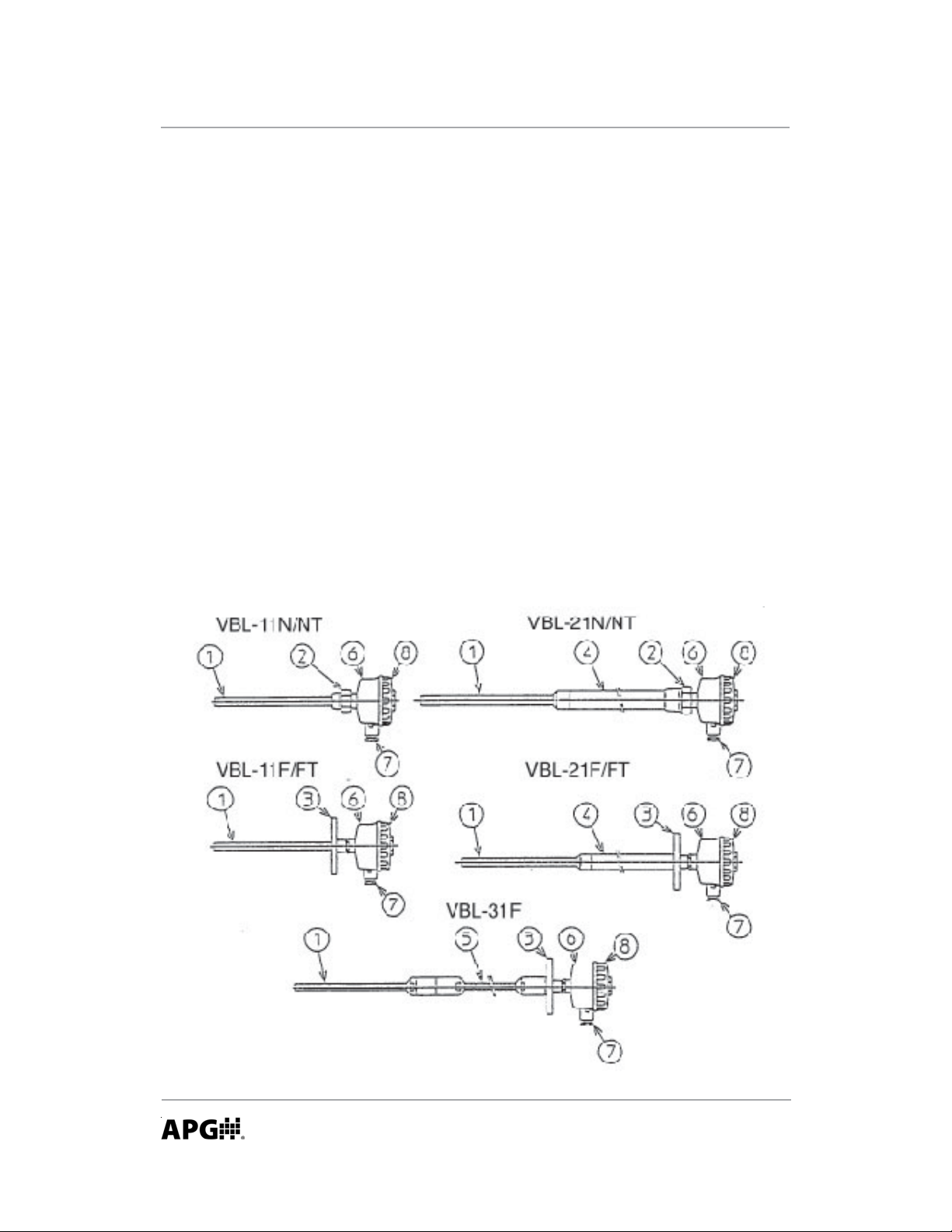
• Nomenclature
1. Vibration Pipe
Detecting part which touches
directly to the powders. It
vibrates when there’s no
powders, but vibration will
dampen or stop when it becomes
buried in the measured materials.
2. Plug for VBL-12N/NT and VBL22N/NT
Screw to install the sensor to the
tank.
3. Flange for VBL-12F/FT ,
VBL-22F/FT and VBL-32F
Flange to install the sensor to the
tank.
4. Extension pipe for VBL-22F/FT
and VBL-22N/NT
Sensor measuring length
extension part.
5. Flexible cable for VBL-32F
Sensor measuring length
extension part.
6. Housing
Electronic circuit is placed.
7. Cable Gland
Cable entry to enter the cable.
Sizes are JIS F 20a (G 3/4) and JIS
F 15c (G 1/2) (Optionally
available.)
8. Cover for the sensor.
Automation Products Group, Inc.
APG...Providing tailored solutions for measurement applications
8
T el: 1/888/525-7300 • Fax: 1/435/753-7490 • www.apgsensors.com • sales@apgsensors.com
Page 9

Rev. A2, 9/09 VBL Series
• Electronics
9. Terminals
Output terminal for power
connection and sensor relay
contact signal.
10. Power Indicator
Green lamp lights when the
sensor power is on.
11. Alarm Indicator
Red lamp lights when the sensor
detects the measuring materials.
12. Sensitivity Setting Volume
To set the sensor detecting
sensitivities or to check the
operating condition.
13. Sensitivity Setting Switch
To set the sensor detecting
sensitivities or to check the
operating condition.
14. Meter Test Points
Meter test points for performance
check and fine adjustment of
sensitivity: [Red for positive (+)
point and Black for negative (-)
point.]
Automation Products Group, Inc.
APG...Providing tailored solutions for measurement applications
T el: 1/888/525-7300 • Fax: 1/435/753-7490 • www.apgsensors.com • sales@apgsensors.com
9
Page 10

VBL Series Rev. A2, 9/09
• Principle of Operation
The vibration rod vibrates by installing piezo-electric element and
acceleration pickup mounted vibration board at the tip of the internal pipe. The
piezoelectric element provides vibration and the acceleration pickup detects
changes in the vibrational frequency. Covered with solids dampens vibration of
the vibration pipe. The electronic circuit detects the damping of these vibration
pipe. The electronic circuit detects the damping of these vibration and converts
into an relay output.
10
Automation Products Group, Inc.
APG...Providing tailored solutions for measurement applications
T el: 1/888/525-7300 • Fax: 1/435/753-7490 • www.apgsensors.com • sales@apgsensors.com
Page 11

Rev. A2, 9/09 VBL Series
• Installation
Unpacking
This unit has been thoroughly inspected and carefully packed at the factory
to prevent damage shipment. When unpacking, open shipping cartons of unit
and inspect the units for shipping damage. If there is evidence of damage, notify
the carrier immediately . Also verify the contents for properly ordered units.
Environment
The VBL should be installed in an area which meets the following conditions:
• The ambient temperature range is within the following:
Housing Probe
VBL-12/22/32 -20 to +60°C -20 to +150°C
VBL-12-T/VBL22-T -20 to +50°C -20 to +150°C
Note: Install a sun shield over the housing if exposed to direct sunlight. Do
not install in an area where the ambient temperature drops rapidly (for
example, 40°C to 0°C). This may cause dew and damage the sensor .
• Locate away from splashing water. The housing protection is IP65.
• No corrosive gases (such as NH3, SO2, C12, etc.).
• Nonhazardous area.
• Ample space is provided for maintenance/inspection.
Location
• Locate the VBL at the position where the material level will actually make
contact with the probe. In case of high level control, pay attention to the
angle of repose. In case of low level control, prevent from being surrounded
by dead stock.
• The maximum length for the threaded boss/standoff pipe is 70 mm.
• The vibration rod should not be in contact with standoff pipe or tank wall.
• The VBL may be mounted in any position or orientation. However, it is
recommended that the cable entry be pointed downward where possible to
prevent intrusion from rain or splashing.
• In case of negative or positive pressure in the container, use suitable pipe
compound, gaskets or thread tape.
Automation Products Group, Inc.
APG...Providing tailored solutions for measurement applications
T el: 1/888/525-7300 • Fax: 1/435/753-7490 • www.apgsensors.com • sales@apgsensors.com
11
Page 12

VBL Series Rev. A2, 9/09
Installation
• The maximum load at the tip of the vibration is 60 kgf. If it exceeds, the
vibration pipe will be bent. Install the guard at least 100 mm above the
vibrating pipe if necessary.
Automation Products Group, Inc.
APG...Providing tailored solutions for measurement applications
12
T el: 1/888/525-7300 • Fax: 1/435/753-7490 • www.apgsensors.com • sales@apgsensors.com
Page 13

Rev. A2, 9/09 VBL Series
• The maximum length for the threaded boss/mounting nozzle is 70 mm. If
exceeds 70 mm, the sensor will detect the dead stock despite there aren’t
any measuring materials in case of horizontal mounting.
• The vibration pipe will not vibrate despite there aren’t any measuring
materials.
• When used as a high level control, calculate the angle of repose for
measuring materials and install the vibration rod where it surely covers.
• When using as a low level control, install the guard above the vibration rod
as bridge or overload is anticipated.
Automation Products Group, Inc.
APG...Providing tailored solutions for measurement applications
T el: 1/888/525-7300 • Fax: 1/435/753-7490 • www.apgsensors.com • sales@apgsensors.com
13
Page 14

VBL Series Rev. A2, 9/09
• Adjustment Procedure
Fundamentally , the model VB L needs no adjustments. But adjust the
detecting sensitivity for:
• Fine powders
• Highly fluidized powders
• Sticky and buildup materials.
• Improper adjustment
Powder Detecting Sensitivity
The adjustment of the detecting
sensitivity depends on bulk density,
fluidity, buildups concentrate features and
so on. Accordingly, the data written below
will be nearly general. See the table below:
Polycarbonate pellet (PC pellet), salt,
powdered coffee’s detecting sensitivities
are written below for your reference.
Detecting Levels
Standard Super High
Powder Names Bulk Density Sensitivity Sensitivity
Salt 1.4 Less than 20 mm Less than 20 mm
PC Pellet 0. 7 Less than 40 mm Less than 10 mm
Powdered Coffee 0.26 Undetectable Less than 80 mm
Standard Sensitivity: The sensitivity when shipping
Super High Sensitivity: The most high detecting sensitivity.
14
Automation Products Group, Inc.
APG...Providing tailored solutions for measurement applications
T el: 1/888/525-7300 • Fax: 1/435/753-7490 • www.apgsensors.com • sales@apgsensors.com
Page 15

Rev. A2, 9/09 VBL Series
Adjusting the detecting sensitivity
• Prepare the following equipment:
- 0 ~ 10 V AC range tester. (In case of voltmeter , input resistive more than
10ý.)
- Small-sized slotted blade screw driver .
• Clean up the vibration pipe. While adjusting, make sure the measuring
materials are not contacting the vibration rod. If it contacts, exact
adjustment will be impossible.
• Turn on the power supply if it is not on.
• Wait for 5 seconds.
• Set the sensitivity setting switch to AJ (middle point).
• Plug in the positive reed to positive (red) meter test point and negative reed
to negative (black) meter test point. Adjust the tester to voltage range
which can detect the direct current 0 ~ 10 V every 0.5 V.
- Super-high sensitivity for highly fluidized powders. Adjust the check
terminal voltage to 4.5 ~ 5.5 V by sensitivity setting volume. Set the
sensitivity switch to H (high sensitivity range).
- High sensitivity for fine powders. Adjust the check terminal voltage to
2 ~ 3 V by sensitivity setting to L (ordinary sensitivity range).
- Low sensitivity for sticky and build-up material. Adjust the check terminal
voltage to 4.5 ~ 5.5 V by sensitivity setting volume. Set the sensitivity
switch to L (ordinary sensitivity range).
Consult APG for repair or replacement in case of indicating the incorrect
voltage.
Automation Products Group, Inc.
APG...Providing tailored solutions for measurement applications
T el: 1/888/525-7300 • Fax: 1/435/753-7490 • www.apgsensors.com • sales@apgsensors.com
15
Page 16

VBL Series Rev. A2, 9/09
• Sensitivity
The sensitivity can be adjusted by using the sensitivity switch and by
adjusting the voltage.
H with 4.5~5.5 VDC: for highly fluidized materials.
L with 2.0~3.0 VDC: for light materials.
L with 4.5~5.5 VDC: standard adjustment (bulk density 0.2/cm3 or more)
L with 6.0~7.0 VDC: for sticky materials.
Set the sensitivity switch to AJ.
Turn sensitivity volume until the desired voltage is read.
After adjustment, set the switch to H or L and make sure 8~10 VDC can be
read.
16
Automation Products Group, Inc.
APG...Providing tailored solutions for measurement applications
T el: 1/888/525-7300 • Fax: 1/435/753-7490 • www.apgsensors.com • sales@apgsensors.com
Page 17

Rev. A2, 9/09 VBL Series
• Wiring
Wiring should be in accordance with all local codes. Control cable should be a
minimum of 0.75 mm2.
• Contact capacity
240 V 3 A AC (Resistive)
30 V 3 A DC (Resistive)
• Power supply
90 to 132 V AC 50/60 Hz
180 to 264 V AC 50/60 Hz
• Power consumption
5 V A
Caution: Make sure the
supply voltage matches the
markings on the circuit board
terminals. Applying the wrong
voltage or miswiring will
damage the sensor and may
cause injury.
• Start Up
1. Test Points
For fine adjustment of the
sensitivity.
2 . Sensitivity Switch
To set high or low
sensitivity.
3 . Sensitivity V olume
To adjust the sensitivity.
4 . Detection Status LED
5 . Power Status LED
Automation Products Group, Inc.
APG...Providing tailored solutions for measurement applications
T el: 1/888/525-7300 • Fax: 1/435/753-7490 • www.apgsensors.com • sales@apgsensors.com
17
Page 18

VBL Series Rev. A2, 9/09
• Maintenance
In general, the sensitivity properly set VBL needs no maintenance. But in
order to use the sensor stable for a long time, maintenance and inspection are
needed in periodic intervals.
Inspection
Inspection is held to examine
• If the sensitivity is set to proper sensitivity.
• If it is affected by the build-up.
• If the sensor is operating correctly.
Proceed as follow:
• Make sure the measuring materials are not touching the vibrating pipe.
Replace the sensor out of the tank if necessary.
• Supply power to the sensor.
• Make sure which the sensor sensitivity is set. Super-high, high, standard
(shipping sensitivity) or low.
• Prepare the 0 ~ 10 VDC range voltmeter .
• Plug the voltmeter leads to the test points, positive to Red (+) and negative
to Black (-).
• See the table below. Ensure both A and B stated voltage can be read for
each set sensitivity.
Position for Sensitivity Setting
Switch and Voltage Reading
Set Sensitivity A B
Super-high H: 8 ~ 9 V AJ: 4.5 ~ 5.5 V
High L: 8 ~ 9 V AJ: 2.0 ~ 3.0 V
Standard L: 8 ~ 9 V AJ: 4.5 ~ 5.5 V
Lo w L: 8 ~ 9 V AJ: 6.0 ~ 7.0 V
• If the voltage reading is accomplished, the sensitivity adjustment is correct.
Nevertheless malfunction occurs. See Troubleshooting section.
• If the voltage reading is low, clean up the build-up on the vibration rod.
Then adjust the sensitivity volume in the state of sensitivity setting switch
is AJ until the correct voltage can be read. Otherwise, the sensor is
defective. Consult APG for repair/replacement.
Automation Products Group, Inc.
APG...Providing tailored solutions for measurement applications
18
T el: 1/888/525-7300 • Fax: 1/435/753-7490 • www.apgsensors.com • sales@apgsensors.com
Page 19

Rev. A2, 9/09 VBL Series
• If the voltage reading is high, the sensitivity adjustment is not properly set.
Adjust the sensitivity volume in the state of sensitivity setting switch is AJ
until the correct voltage can be read. Otherwise, the sensor is defective.
Consult APG for repair/replacement.
Maintenance
In order to use model VBL for a long time, maintenance is needed in periodic
intervals. Periodic inspections are important to maintain good service.
Maintenance method is as follow:
• A large amount of build-up on the tip of the vibration rod will cause wrong
signal output. Clean build-up in periodic intervals in case of measuring
strong adherence materials.
• Make sure the raindrops (waterdrops) are not intruding inside the housing.
For outdoor use, the waterdrops will intrude easily if the housing cover or
the cable entry is loose. Intrude of the waterdrops will cause an erroneous
signals, make sure to tighten periodically . A crack of water-drop-proof Oring (special article) between housing and cover will deteriorate the waterdrop-proof. Replace it with new ones.
• Depending on the measuring materials, the sensor will cause corrosion or
rubbing. Make sure the corrosion and rubbing are not outbreaking or
progressing periodically ,
Automation Products Group, Inc.
APG...Providing tailored solutions for measurement applications
T el: 1/888/525-7300 • Fax: 1/435/753-7490 • www.apgsensors.com • sales@apgsensors.com
19
Page 20

VBL Series Rev. A2, 9/09
• Troubleshooting
Problem
Not detecting powders when covered.
Possible Causes
• Powder build density is too small. Bulk density under 0.2 cannot be
detected.
• Power supply not connected.
• Material too fluid.
• Effected by heavy hopper vibration.
Remedies
• Set high sensitivity
• Connect power supply.
• Install sensor in a better location.
Problem
• It keeps detecting powders while the hopper is empty.
Possible Causes
• Heavy deposit on vibration rod.
• Material has dead stock.
Remedies
• Clean vibration rod.
• Install sensor in better location or isolate dead stock.
20
Automation Products Group, Inc.
APG...Providing tailored solutions for measurement applications
T el: 1/888/525-7300 • Fax: 1/435/753-7490 • www.apgsensors.com • sales@apgsensors.com
Page 21

Rev. A2, 9/09 VBL Series
Notes
Automation Products Group, Inc.
APG...Providing tailored solutions for measurement applications
T el: 1/888/525-7300 • Fax: 1/435/753-7490 • www.apgsensors.com • sales@apgsensors.com
21
Page 22

VBL Series Rev. A2, 9/09
Notes
22
Automation Products Group, Inc.
APG...Providing tailored solutions for measurement applications
T el: 1/888/525-7300 • Fax: 1/435/753-7490 • www.apgsensors.com • sales@apgsensors.com
Page 23

Rev. A2, 9/09 VBL Series
Notes
Automation Products Group, Inc.
APG...Providing tailored solutions for measurement applications
T el: 1/888/525-7300 • Fax: 1/435/753-7490 • www.apgsensors.com • sales@apgsensors.com
23
Page 24

PRODUCTS
AUT OMATION
APG ...Providing tailored solutions
for measurement applications
Automation Products Group, Inc.
Tel: 1/888/525-7300
1/435/753-7300
Fax: 1/435/753-7490
GROUP, INC.
e-mail: sales@apgsensors.com
www.apgsensors.com
Automation Products Group, Inc.
1025 W. 1700 N.
Logan, UT 84321
 Loading...