

Page 1
SERIES 100 CASH DRAWER
OPERATING & MAINTENANCE
INSTRUCTIONS
This instruction sheet applies to
the Series 100 cash drawer
products
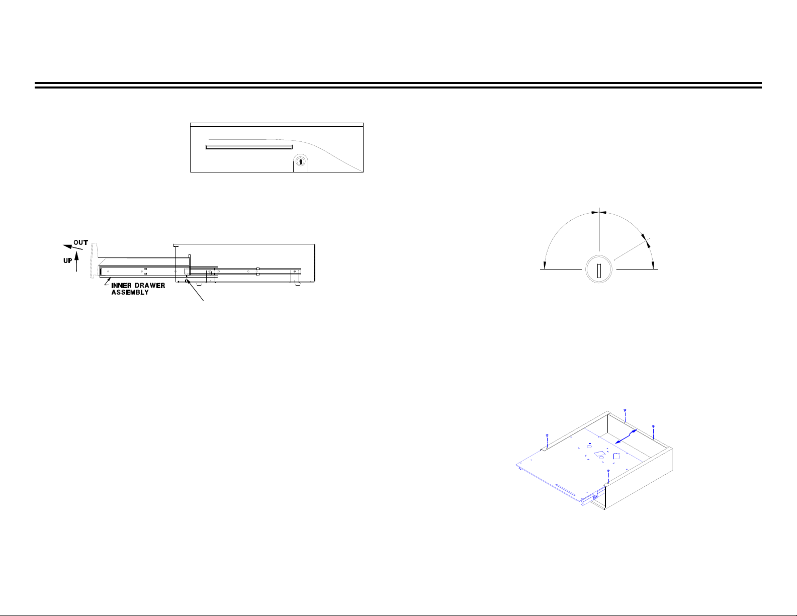
REMOVING THE INNER
DRAWER FROM THE CASH DRAWER
Open the cash drawer and remove the plastic coin and bill tray. Grasp the
inner drawer by the drawer front and lift the inner drawer up until it stops.
Firmly pull the inner drawer out at the inclined angle. See figure 2.
FIGURE 2 - Remove the Inner Drawer by lifting up and out. Note the drawer stop of the
inner drawer must pass over the stop plate in the base for removal and/or reinsertion.
REPLACING THE INNER DRAWER INTO THE CASH DRAWER
Mate the outer slides, mounted to the inner drawer, with the inner slides mounted to
the chassis inside the cash drawer. Lift the inner drawer up until
it stops and begin to push the inner drawer into the cash drawer housing. When the
drawer stop on the back of the inner drawer has cleared the stop plate formed from the
base, let the inner drawer rest in the horizontal position. See figure 2. Push the inner
drawer to the fully closed position. Resistance to the insertion should be expected,
because the ball bearings do not roll until the slides are fully engaged. When the inner
drawer is fully inserted, verify the drawer opens and closes properly using the key.
The drawer should open and close smoothly through the full extent of the slides.
PREVENTIVE MAINTENANCE
Lubricate the slide assembly periodically. Maintain a thin film of lithium based
bearing grease on the ball bearings in the slides. Operating conditions govern the
frequency of inspection and lubrication. Under heavy use, inspect, clean, and lubricate
the slide assembly more frequently. Avoid breaking coin rolls over the plastic coin and
bill tray or on the drawer front.
LOCK ASSEMBLY
Two keys are included with each cash drawer for the manual lock. The manual key
lock mechanism provides four functions: locked open, manual open, electrically online, and locked closed. See figure 3. To reduce the risk of damaging or breaking the
key, avoid leaving it in the lock during normal operation.
Electrically
On-Line
Manual
Open
Locked
Closed
Locked
Open
Figure 3 - LOCK POSITIONS AND FUNCTIONS
AS VIEWED FROM FRONT
CASE REMOVAL INSTRUCTIONS
A #2 Phillips head screwdriver is required to remove the case.
1. Remove the coin and bill tray and the inner drawer (see Figure #2). Turn the cash
drawer over with the drawer front opening toward you.
2. Remove the screws that secure the base to the case. Two are located along the back
edge, and two are located along the front edge. See figure 4.
FIGURE 4 - REMOVING THE BASE FROM THE CASE
3. Slide the base assembly out towards the front.
4. Replace the base by reinserting it in from the front of the case and under the case
side flanges. Slide the base on top of the case lip at the rear of the case.
M-423 Rev B
 Loading...