

Page 1
APG
Thank You
using a non-POE
Thanks for purchasing a RST-5003 control module from us! We appreciate your business and
your trust. Please take a moment to familiarize yourself with the product and this manual before
installation. If you have any questions, at any time, don’t hesitate to call us at 888-525-7300.
RST-5003 Control Module
Installation Guide
NOTE: Scan the QR code to the below to visit www.apgsensors.com/support.
APG Support Website
Table of Contents
1.Description
2. How To Read Your Label
3. Warranty
4. Installation Procedure
Description
1
The RST-5003 Web Enabled Control Module oers a wide degree of integrated and exible remote
and local control and monitoring for your system. The RST-5003 can control up to ten APG Modbus
sensors--any combination of level, pressure, magnetostrictive and ultrasonic--along with one
4-20 mA sensor, and two input or out relay terminals. All readings are available for control and
monitoring via TCP/IP for local or remote network access. The RST-5003 also had exible power
options: it can use either POE or an independent 12-28 VDC power source.
5. Dimensions
6. Power Supply Wiring
Diagrams
7. Modbus System Wiring
Diagrams
8. Embedded Webpage
9. General Care
10. Repair Information
11. Removal Instructions
Web Enabled Series
R
Automation Products Group, Inc.
1025 W 1700 N Logan, UT 84321
www.apgsensors.com | phone: 888-525-7300 | email: sales@apgsensors.com
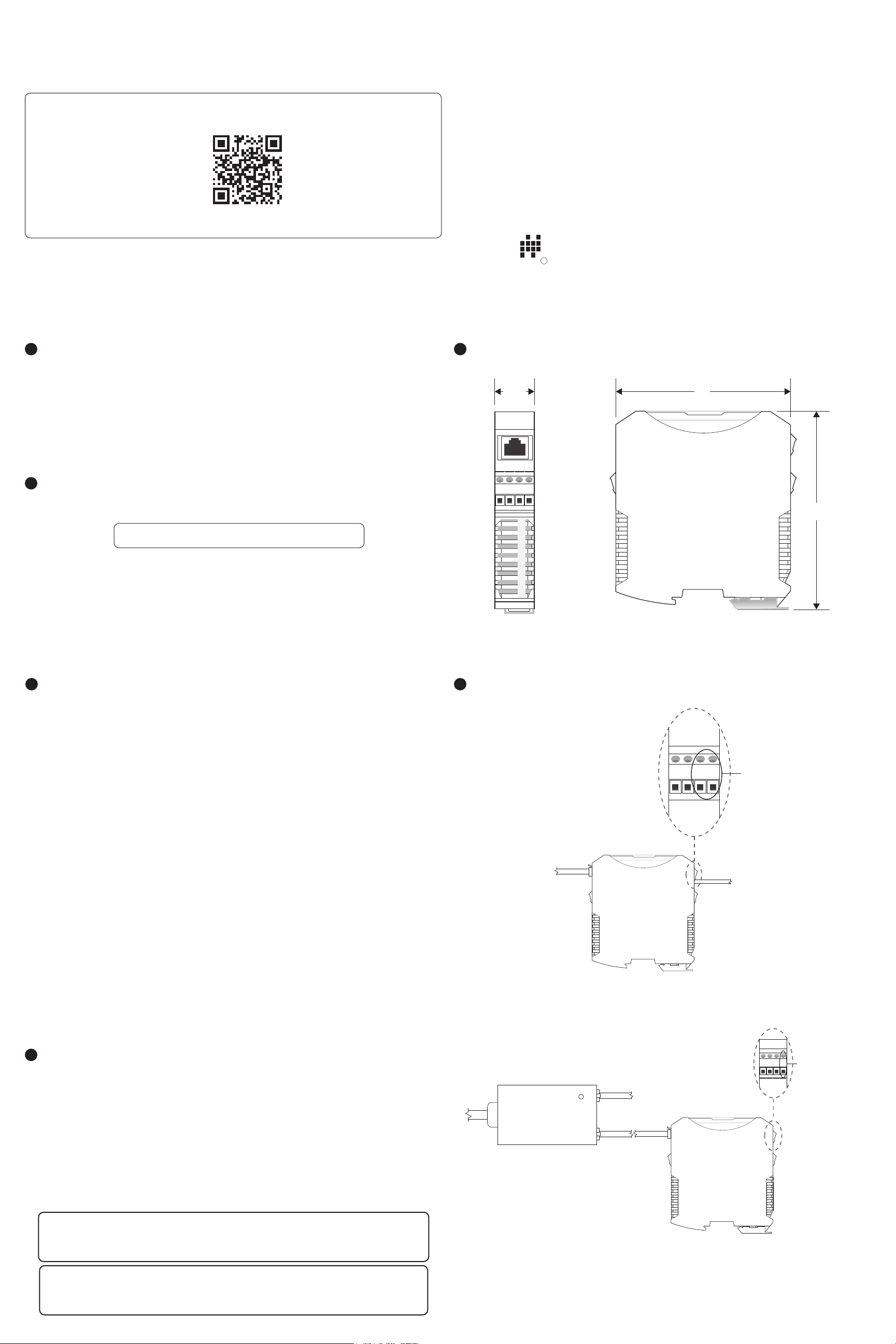
Dimensions
5
7/8”
4”
Part # 122950-0012
Doc #9004245 Rev A
How To Read Your Label
2
Each label comes with a full model number, a part number, and a serial number. The model
number for the RST-5003 will look something like this:
SAMPLE: RST-5013
The model number correlates with all the congurable options and tells you exactly what you have.
Compare the model number to the options on the datasheet to identify your exact conguration.
You can also call us with the model, part, or the serial number and we can help you.
Warranty
3
APG warrants its products to be free from defects of material and workmanship and will, without
charge, replace or repair any equipment found defective upon inspection at its factory, provided
the equipment has been returned, transportation prepaid, within 24 months from date of shipment
from factory.
THE FOREGOING WARRANTY IS IN LIEU OF AND EXCLUDES ALL OTHER WARRANTIES NOT
EXPRESSLY SET FORTH HEREIN, WHETHER EXPRESSED OR IMPLIED BY OPERATION OF LAW OR
OTHERWISE INCLUDING BUT NOT LIMITED TO ANY IMPLIED WARRANTIES OF MERCHANTABILITY
OR FITNESS FOR A PARTICULAR PURPOSE.
2
G
4
N
B
A
V
D
Power Supply Wiring Diagrams
6
4 1/2”
G
G
4
2
0
2
N
N
4
D
D
V
Input for supply
voltage when
power source
No representation or warranty, express or implied, made by any sales representative, distributor,
or other agent or representative of APG which is not specically set forth herein shall be binding
upon APG. APG shall not be liable for any incidental or consequential damages, losses or expenses
directly or indirectly arising from the sale, handling, improper application or use of the goods or
from any other cause relating thereto and APG’s liability hereunder, in any case, is expressly limited
to the repair or replacement (at APG’s option) of goods.
Warranty is specically at the factory. Any on site service will be provided at the sole expense of the
Purchaser at standard eld service rates.
All associated equipment must be protected by properly rated electronic/electrical protection
devices. APG shall not be liable for any damage due to improper engineering or installation by the
Purchaser or third parties. Proper installation, operation and maintenance of the product becomes
the responsibility of the user upon receipt of the product.
Returns and allowances must be authorized by APG in advance. APG will assign a Return Material
Authorization (RMA) number which must appear on all related papers and the outside of the
shipping carton. All returns are subject to the nal review by APG. Returns are subject to restocking
charges as determined by APG’s “Credit Return Policy”.
Installation Procedure
4
Installing your RST-5003 is easy if you follow a few simple steps:
• Connect any 4-20 mA sensor, relays, or switched inputs rst.
• Connect RST to Ethernet/network
• Connect independant 12-28 VDC supply if not using POE.
• Connect and set up one Modbus sensor at a time.
Please keep the following limitations in mind:
To AC
power
To Network
Connection
External 12-28VDC Power Supply Wiring
POE
Power
Injector
POWER
LAN + DC LAN
RST-5003
To Network Connection
To 12-28 VDC
Power Source
RST-5003
Provides 24 VDC
G
2
N
4
D
V
to supply a 4-20 mA
device when the RST
is powered via POE.
G
4
N
2
D
0
• Up to 10 Modbus sensors can be connected to the RST-5003 in any combination.
• Only one 4-20 mA sensor can be connected to the RST-5003.
IMPORTANT: Each Modbus sensor must be added to the network individually and
assigned a unique Sensor Number before the next sensor can be added.
NOTE: If you can control power to each Modbus sensor individually, you can connect
them all simultaneously, and power them on individually.
NOTE: A POE-enabled
Ethernet switch eliminates
the need for a POE Power
Injector.
POE (Power Over Ethernet) Wiring
Page 2

Modbus System Wiring Diagrams
7
Server Hosting
Website and
Logged Data
Network / Internet Connection
Connection
to
Internet
Modbus
Input
RST-5003
4-20 mA Input
(2) Solid State Relays
Computer
on
Internet
Computer
on
Local
Network
Equivalent 270 Ω
terminating resistor
internal to RST-5003
(Ethernet Port)
2
G
4
N
B
A
V
D
Use shielded cable
Sensor Line Drops
B
A
V+
GND
Sensor 1
Modbus Daisy Chain Wiring
Note: Terminating resistor size recommended
based on input resistance of RST-5003. Length
of cable and overall impedence of network may
necessitate a different size resistor.
Trunk Line
270 Ω
terminating
resistor at
last sensor
B
A
V+
GND
Sensor 2
B
Sensor 3
A
V+
GND
4-20 mA Type Level Sensor
MNU Ultrasonic Sensors MP Magnetostrictive Float Level Sensors
Modbus System & Network Diagram
Accessing the RST-5003’s Embedded Webpage
8
Each Modbus sensor attached to your RST-5003 must be congured via the RST-5003’s embedded
webpage before the next sensor can be added. The easiest way to access access the embedded
webpage is to type rst_xxx into a web browser on a computer connected to the same local network
as the RST-5003. xxx represents the numeric portion of the RST-5003’s serial number. See Figures
8.1 and 8.2.
NOTE: Refer to each sensor’s user manual for sensor specic wiring instructions. User
Manuals for all APG sensors and equipment are available at www.apgsensors.com.
Figure 8.1
General Care
9
Your RST-5003 is very low maintenance and will need little care as long as it was installed correctly.
However, in general, you should:
• Avoid applications for which the control module was not designed, such as extreme
temperatures, contact with incompatible corrosive chemicals and fumes, or other damaging
environments.
Repair Information
10
If your RST-5003 control module needs repair, contact us via email, phone, or on-line chat on our
website. We will issue you an RMA number with instructions.
• Phone: 888-525-7300
• Email: sales@apgsensors.com
• Online chat at www.apgsensors.com
Removal Instructions
11
• Disconnect power source to control module.
• Disconnect sensors and network cable to control module.
• Remove the control module and store it in a dry place, at a temperature between -40° F and
180° F.
Figure 8.2
IMPORTANT: See your RST-5003 User Manual for complete Modbus programming
instructions and tropubleshooting tips..
 Loading...