

Page 1

APG
RST-5003 Control Module
User Manual
Web Enabled Series
R
Doc #9004240
Rev A1, 05/2016
Page 2

Table of Contents
Introduction ................................................................................................................ iii
Warranty and Warranty Restrictions .................................................................... iv
Chapter 1: Specications and Options.....................................................................1
Dimensions ........................................................................................................................................1
Specications ...................................................................................................................................2
Model Number Congurator .......................................................................................................... 3
System Wiring Diagrams ............................................................................................................3-5
Chapter 2: Installation and Removal Procedures and Notes ..............................6
Tools Needed .....................................................................................................................................6
Connection Notes ............................................................................................................................. 6
Electrical Installation .....................................................................................................................6
Software Setup ............................................................................................................................ 7-11
Removal Instructions ....................................................................................................................11
Chapter 3: Programming with Modbus TCP/IP ................................................... 12
Modbus Polling via Ethernet with Modbus TCP/IP ...........................................................12-13
RST-5003 Generic Modbus Register List ................................................................................... 13
Modbus Programming of Individual Sensors .......................................................................... 14
Chapter 4: RST-5003 Embedded Web Server ........................................................ 14
Accessing the RST-5003 Embedded Web Server .................................................................... 14
Navigating the RST-5003 Embedded Web Server ..............................................................14-15
4-20 mA Sensor Input Conguration Submenus .............................................................. 16-29
Modbus Sensor Conguration Registers ............................................................................ 30-32
RST-5003 Utility Menus ......................................................................................................... 33-36
Chapter 5: Maintenance ...........................................................................................37
General Care .................................................................................................................................... 37
Repair and Returns ........................................................................................................................37
ii
Tel: 1/888/525-7300 • Fax: 1/435/753-7490 • www.apgsensors.com • sales@apgsensors.com
Page 3

Introduction
Thank you for purchasing an RST-5003 Web Enabled Control Module from APG. We appreciate your
business! Please take a few minutes to familiarize yourself with your RST-5003 and this manual.
The RST-5003 Web Enabled Control Module oers a wide degree of integrated, exible, remote and local
control and monitoring for your system. The RST-5003 can control up to 10 APG Modbus sensors--any
combination of level, pressure, magnetostrictive and ultrasonic--along with one 4-20 mA sensor, and two
input or output relay terminals. All readings are available for control and monitoring via TCP/IP for local
or remote network access. The RST-5003 also had exible power options: it can use either POE or an
independent 12-28 VDC power source.
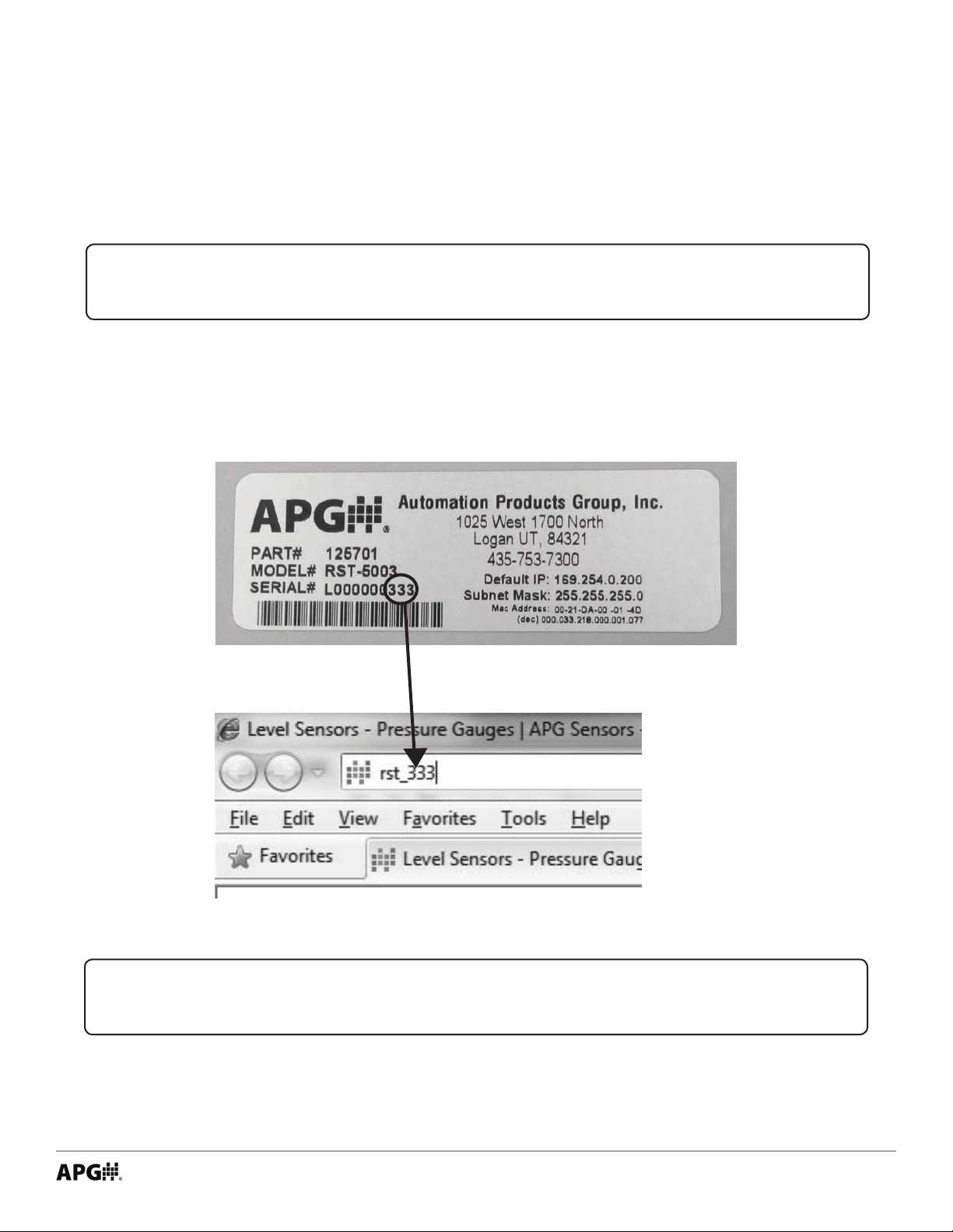
Reading your label
Every APG controller comes with a label that includes the controller’s model number, part number, and
serial number. The RST-5003 label also indicates the default IP address, subnet mask, and mac address.
Please ensure that the model number on your label matches your order.
Tel: 1/888/525-7300 • Fax: 1/435/753-7490 • www.apgsensors.com • sales@apgsensors.com
iii
Page 4

Warranty and Warranty Restrictions
This product is covered by APG’s waranty to be free from defects in material and workmanship under
normal use and service of the product for 24 months. For a full explanation of our Warranty, please visit
https://www.apgsensors.com/about-us/terms-conditions. Contact Technical Support to recieve a Return
Material Authorization before shipping your product back.
Scan the QR code below to read the full explanation of our Warranty on your tablet or smartphone.
iv
Tel: 1/888/525-7300 • Fax: 1/435/753-7490 • www.apgsensors.com • sales@apgsensors.com
Page 5
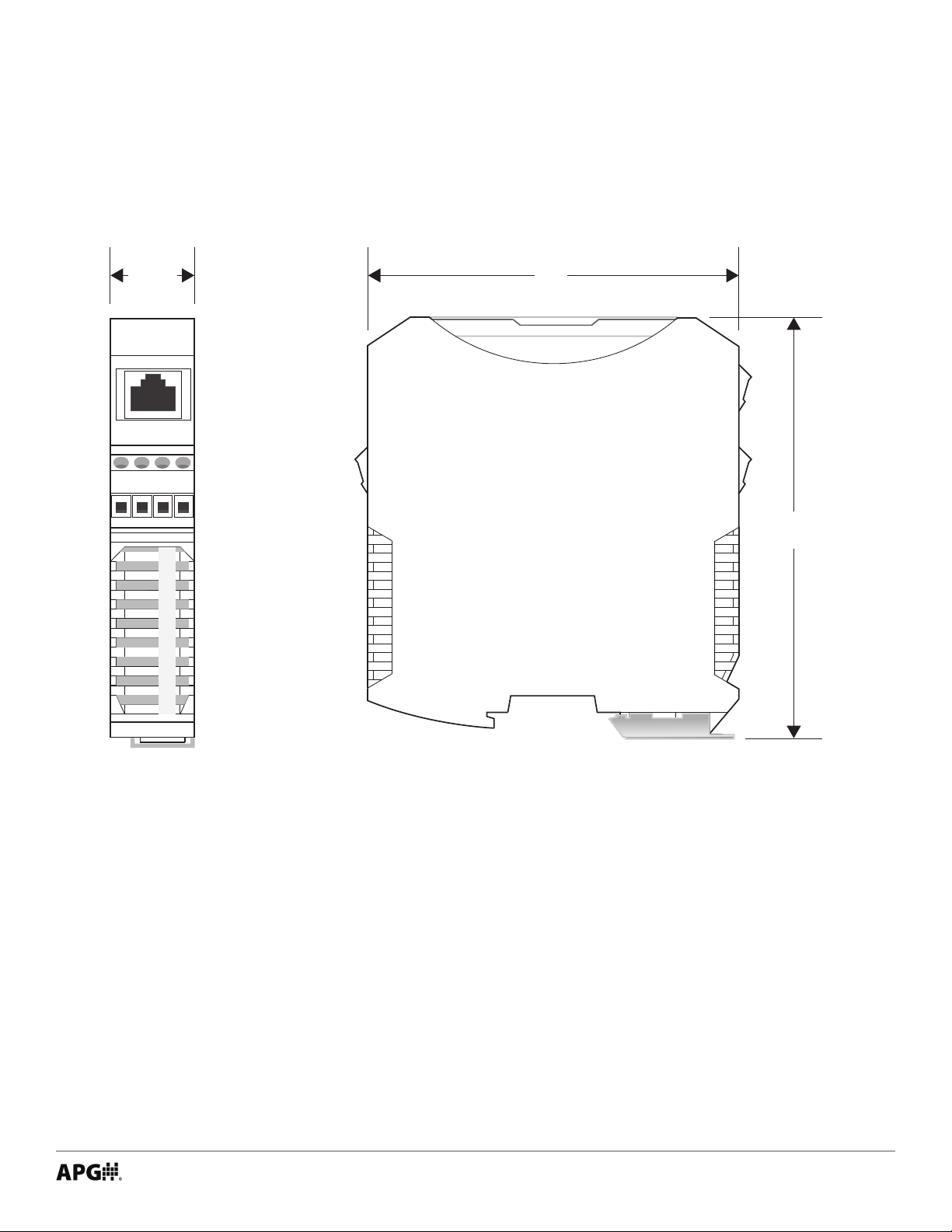
Chapter 1: Specications and Options
• Dimensions
7/8”
B
A
4”
2
G
4
N
V
D
4 1/2”
Tel: 1/888/525-7300 • Fax: 1/435/753-7490 • www.apgsensors.com • sales@apgsensors.com
1
Page 6

• Specications
Communications
Digital Output Ethernet TCP/IP Modbus
Ethernet TCP/IP to internal web page
Ethernet TCP/IP to APG-provided website
0-2 Isolated Solid State Relays
Inputs RS-485 Modbus
4-20 mA
0-2 Discrete Switches
Electrical
Operational Supply Voltage (at sensor) 48 VDC via POE (requires injector or switch)
12-28 VDC
Current Draw 40 mA @ 48 VDC
Power Rating 2.0 W Max
Issolated SSRs 120V, 120 mA Max
Accuracy
Resolution 12 bit
Environmental
Operating Temperature -40 to 60°C (-40 to 140°F)
Materials of Construction
Housing Polyamide
Mounting
33 mm Din-Rail
Compatible APG Modbus Senors
Ultrasonic MNU
Magnetostrictive MPX-E1, MPX-R1
Pressure PT-400-L5, PT-400-L31, PT-500-L5, PT-500-L31
Controllers DCR-1006A, MND
2
Tel: 1/888/525-7300 • Fax: 1/435/753-7490 • www.apgsensors.com • sales@apgsensors.com
Page 7
• Model Number Congurator
using a non-POE
Model Number: RST - _____
A
A. Model
□ 5003 2 relay outputs
□ 5013 1 relay output, 1 switch input
□ 5113 2 switch inputs
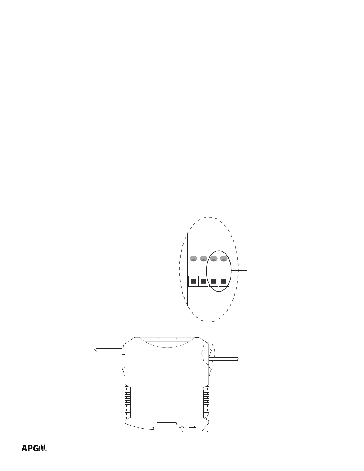
• System Wiring Diagrams
External 12-28 VDC Source Wiring
To Network
Connection
RST-5003
G
4
2
0
G
N
D
2
N
4
D
V
Input for supply
voltage when
power source
To 12-28 VDC
Power Source
Tel: 1/888/525-7300 • Fax: 1/435/753-7490 • www.apgsensors.com • sales@apgsensors.com
3
Page 8
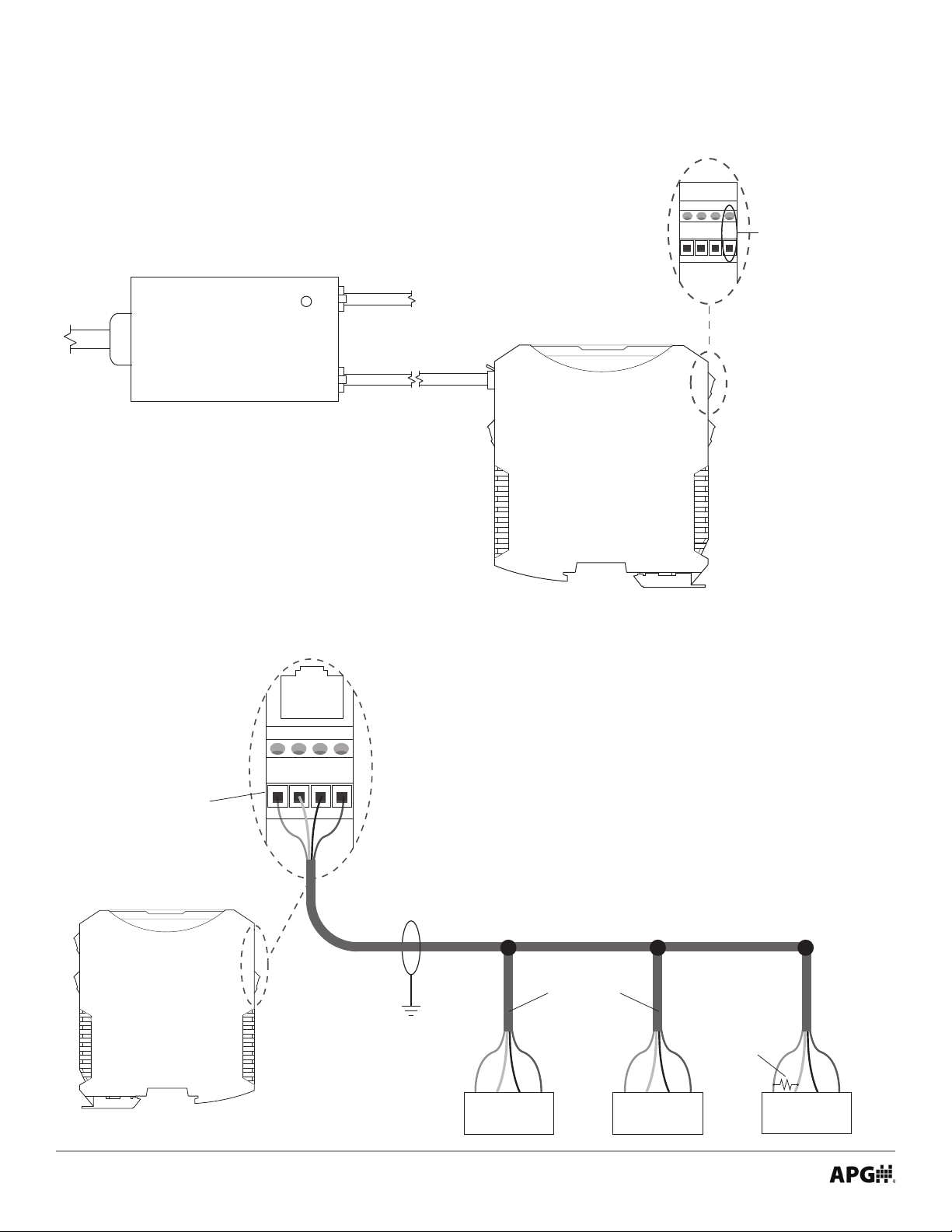
POE (Power over Ethernet) Wiring
Provides 24 VDC
G
G
4
N
N
2
D
D
0
to supply a 4-20 mA
2
4
device when the RST
V
is powered via POE.
To AC
power
POWER
POE
Power
Injector
LAN + DC LAN
NOTE: A POE-enabled
Ethernet switch eliminates
the need for a POE Power
Injector.
Modbus Sensor Daisy-chain Wiring
(Ethernet Port)
To Network Connection
RST-5003
2
G
4
N
B
Equivalent 270 Ω
terminating resistor
internal to RST-5003
4
A
V
D
Note: Terminating resistor size recommended
based on input resistance of RST-5003. Length
of cable and overall impedence of network may
necessitate a different size resistor.
Use shielded cable
Trunk Line
Sensor Line Drops
B
A
V+
GND
Sensor 1
Tel: 1/888/525-7300 • Fax: 1/435/753-7490 • www.apgsensors.com • sales@apgsensors.com
B
A
Sensor 2
GND
270 Ω
terminating
resistor at
last sensor
V+
B
A
Sensor 3
GND
V+
Page 9

System Overview - RST-5003 with Modbus and 4-20 mA sensors and Internet Connection
Server Hosting
Website and
Logged Data
Network / Internet Connection
Connection
to
Internet
Computer
on
Internet
Computer
on
Local
Network
4-20 mA Input
RST-5003
Modbus
Input
(2) Solid State Relays
4-20 mA Type Level Sensor
MNU Ultrasonic Sensors MP Magnetostrictive Float Level Sensors
Tel: 1/888/525-7300 • Fax: 1/435/753-7490 • www.apgsensors.com • sales@apgsensors.com
5
Page 10
Chapter 2: Installation and Removal Procedures and Notes
• Tools Needed
• You do not need any tools to install your RST-5003. Please consult each sensor’s user manual for any
sensor installation notes and instructions.
NOTE: For any APG sensor user manual, please visit http://apgsensors.com/support.
• Connection Notes
• Up to 10 Modbus sensors can be connected to the RST-5003 in any combination.
• Only one 4-20 mA sensor can be connected to the RST-5003.
IMPORTANT: Each Modbus sensor must be connected to the network individually and
assigned a unique Sensor Number before the next sensor can be added.
• Electrical Installation
• Connect any 4-20 mA sensor, relays, or switched inputs rst.
• Connect RST to Ethernet/network.
• Connect independant 12-28 VDC supply if not using POE.
• Connect and set up one Modbus sensor at a time.
IMPORTANT: Multiple Modbus sensors added to the network simultaneously are all
assigned the same Modbus address/sensor number: 1. Sensors MUST be added to the
network individually.
6
Tel: 1/888/525-7300 • Fax: 1/435/753-7490 • www.apgsensors.com • sales@apgsensors.com
Page 11
• Software Setup
Initial setup of the RST-5003 and individual Modbus sensors is done via an embedded web server. The page
can be accessed by using either the serial number or local IP address of the RST-5003 and a web browser
(Internet Explorer, Chrome, Firefox, etc).
NOTE: Port 6700 must be open on your local network for the RST-5003 to connect.
Accessing RST-5003 Embedded Web Server
The easier way to access the embedded web server is to type rst_xxx into a web browser on a computer
connected to the same local network as the RST-5003. xxx represents the numeric portion of the RST-5003’s
serial number. See Figures 2.1 and 2.2.
Figure 2.1
Figure 2.2
NOTE: If your web browser performs a web search for “rst_xxx” istead of loading the
page, type “http://rst_xxx”.
Some networks will block this direct access to the RST-5003. If this is the case, you will need to use the IP address of your RST-5003 to access the embedded web server. The IP address can be obtained two ways: ask
your local network administrator, or logon to your APG-provided website, www.levelandow.com.
Tel: 1/888/525-7300 • Fax: 1/435/753-7490 • www.apgsensors.com • sales@apgsensors.com
7
Page 12
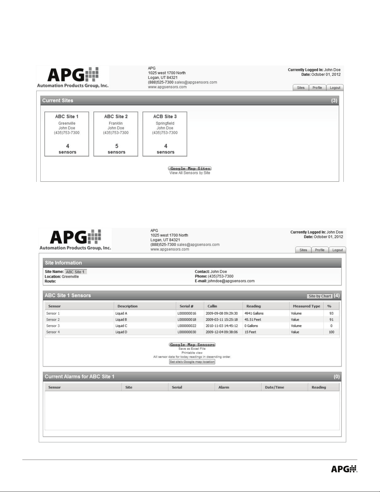
After logging on to your APG-provided website, a list of sites will be displayed on your screen (see Figure
2.3). Select the site where the new RST-5003 is installed.
Figure 2.3
From the list of sensors at this site, select the sensor with the serial number that corresponds to the new
RST-5003. (See Figure 2.4.)
Figure 2.4
8
Tel: 1/888/525-7300 • Fax: 1/435/753-7490 • www.apgsensors.com • sales@apgsensors.com
Page 13
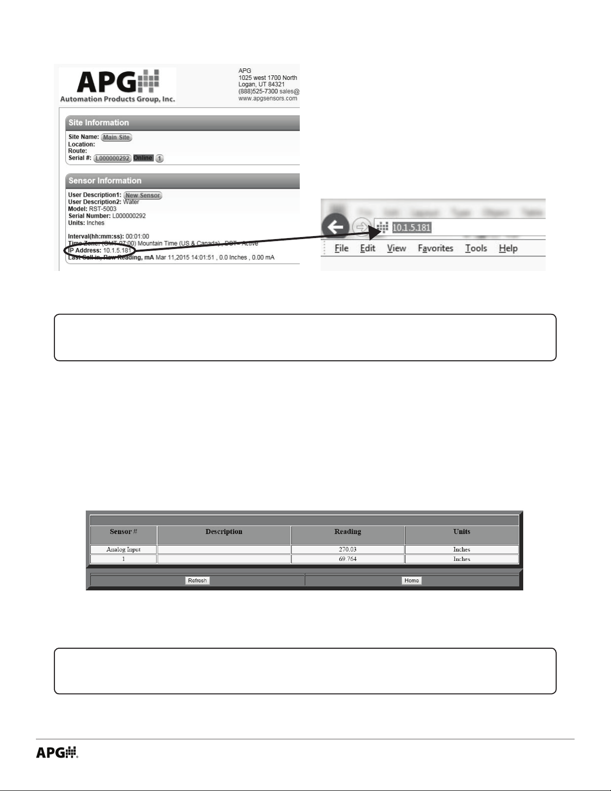
On the Sensor Information screen you will see
the IP Address of the newly installed RST-5003.
(See Figure 2.5.)
Type the RST’s IP address into your browser’s
address bar (See Figure 2.6).
Figure 2.5
Figure 2.6
NOTE: For further information on using your APG-provided remote website, please
visit www.apgsensors.com/support for a user manual, or contact us at 1-888-525-7300.
Logging on to the RST-5003 Embedded Web Server
The RST’s embedded webpage should now be open, showing the Main Display page (See Figure 2.7). This
page lists the sensors attached to the RST-5003 and displays each sensor’s current reading. A 4-20 mA sensor will have “Analog Input” as its Sensor Number. The congured sensor number for each Modbus sensor
will show as its Sensor Number. Every new Modbus sensor defaults to sensor number 1.
Figure 2.7
IMPORTANT: Multiple Modbus sensors added to the network simultaneously are all
assigned the same sensor number: 1. Sensors must be added to the network individually.
Tel: 1/888/525-7300 • Fax: 1/435/753-7490 • www.apgsensors.com • sales@apgsensors.com
9
Page 14

Click on Home to bring up the Menu page (See Figure 2.8). The rst menu link clicked during each session
will prompt a User Name and Password login for the RST-5003 (See Figure 2.9). The default User Name is
admin, and the default Password is password.
Figure 2.8 Figure 2.9
NOTE: See the Security Setting Menu (Page 35) to change this user name and pass-
word.
Assigning Modbus Senor Numbers
Click on RS-485 Network Settings to bring up the RS485 Settings page. (See Figure 2.10.) See section RS-485
Network Settings for a full descrition of each parameter in this menu (Page 36).
10
Figure 2.10
Tel: 1/888/525-7300 • Fax: 1/435/753-7490 • www.apgsensors.com • sales@apgsensors.com
Page 15

Change Numb of Sensors On Line to relfect the total number of Modbus sensors you will be connecting. Click
Change to send the new value to the RST-5003.
With Sensor Number to View set to 1 (for the latest sensor added to the Modbus network), set New Sensor
Number to the highest available number. Click Change to send the new value to the RST-5003.
Repeat this process for each Modbus sensor as it is added to the network.
NOTE: If you control the power to each Modbus sensor seperately, powering up a new
sensor after assigning a Modbus address to the previous sensor will allow you to assign
an address to the new sensor without leaving the RS845 Settings Menu.
IMPORTANT: None of parameters in the RS485 Settings menu automatically update.
Each one must be manually congured.
• Removal Instructions
• Disconnect power to the RST-5003 rst.
• Disconnect network connection.
• Disconnect any sensors, relays, and switched inputs.
• Remove the RST-5003 and store it in a dry place, at a temperature between -40° F and 180° F.
Tel: 1/888/525-7300 • Fax: 1/435/753-7490 • www.apgsensors.com • sales@apgsensors.com
11
Page 16

Chapter 3: Programming with Modbus TCP/IP
• Modbus Polling via Ethernet with Modbus TCP/IP
Using the RST-5003’s IP address, and port number 502, readings can be polled from the RST-5003 for any
attached sensors via RS-485 Modbus commands. Up to 14 32-bit Input Registers, beginning with register
298, can be polled with a single command. Below is a sample Modbus command illustrating the necessary
syntax.
Example:
00 01 : Transaction Identier
00 00 : Protocol Identier
00 06 : Message Length (6 bytes to follow)
0B : The Reporting Unit Identier [i.e., Sensor Number] (0B hex = 11)
04 : The Function Code (04 = read Input Registers)
01 2E : The Data Address of the rst register requested. (12E hex + 1 = 303)
00 02 : The total number of registers requested. (read 2 registers, i.e. 303 to 304)
Byte order (hex values)
00 01 00 00 00 06 0B 04 01 2E 00 02
Notes:
• Reporting Unit indicates the sensor reading being polled from the RST-5003, in hex. 01 - 0A are for Modbus sensors 1 - 10 attached to the RST-5003. 0B reads the interpreted values from the 4-20 mA sensor
attached to the RST-5003. Unused registers (i.e., those not associated to an attached sensor) will return
zeros when polled.
• Function Code 04 reads the Input Registers. No other functionality (e.g., polling from or writing to
Holding Registers) is supported via Modbus TCP/IP with the RST-5003. Complete control functionality is
available through the embedded web server and through your APG-provided website (www.levelandow.com).
• Data Address of registers, decimal to “hex minus 1” conversion:
Decimal Address Hex minus 1 Decimal Address Hex minus 1
299 12A 306 131
300 12B 307 132
301 12C 308 133
302 12D 309 134
303 12E 310 135
304 12F 311 136
305 130 312 137
12
Tel: 1/888/525-7300 • Fax: 1/435/753-7490 • www.apgsensors.com • sales@apgsensors.com
Page 17

• Total number of registers requested, up to 14, given in hex:
# of Registers Hex equivalent # of Registers Hex equivalent
01 01 08 08
02 02 09 09
03 03 10 0A
04 04 11 0B
05 05 12 0C
06 06 13 0D
07 07 14 0E
• RST-5003 Generic Modbus Register List
Input Registers (0x04)
Register Returned Data
30299 Sensor Type
30300 Distance/Level 1, Top (in mm, unsigned)
30301 Distance/Level 2, Bottom (in mm, unsigned)
30302 Sensor Temperature Reading (in 0C, signed)
30303-30304 Calculated 1 (raw)
30305-30306 Calculated 2 (raw)
30307 (upper bits) Version
30307 (lower bits) Signal Strength
30308 Battery Voltage
30309 (upper bits) Sensor Trip 1 Alarm
30309 (lower bits) Sensor Trip 1 Status
30310 (upper bits) Sensor Trip 2 Alarm
30310 (lower bits) Sensor Trip 2 Status
30311 (upper bits) Sensor Trip 3 Alarm
30311 (lower bits) Sensor Trip 3 Status
30312 (upper bits) Sensor Trip 4 Alarm
30312 (lower bits) Sensor Trip 4 Status
This is the list of generic Input Registers for polling the RST-5003 and any connected sensors. Actual registers used vary by sensor. Please see the user manual for each sensor for a full and accurate list of registers.
NOTE: For more information about Modbus RTU, please visit www.modbus.org.
Tel: 1/888/525-7300 • Fax: 1/435/753-7490 • www.apgsensors.com • sales@apgsensors.com
13
Page 18

• Modbus Programming of Individual Sensors
The RST-5003 does NOT support full Modbus programming of attached sensors. Full control and conguration of individual sensors is supported through the RST-5003’s embedded web server and through the
APG-provided webpage, www.levelandow.com.
NOTE: For any APG sensor user manual, please visit http://apgsensors.com/support.
Chapter 4: RST-5003 Embedded Web Server
• Accessing the RST-5003 Embedded Web Server
See the Software Setup section of chapter 2 (pages 7 - 9) for instructions for accessing and signing into the
RST-5003 embedded web server.
• Navigating the RST-5003 Embedded Web Server
The RST-5003 embedded web server has two primary screens--the Main Display Page (Figure 4.1) and Menu
Page (Figure 4.2)--and a screen for each of 9 submenus. The submenus can be understood in three groups:
• 4-20 mA Sensor Input Conguration Submenus
Application Parameters
Analog Parameters
• Modbus Sensor Conguration Registers
RS-485 Modbus Input Reg
RS-485 Modbus Holding 1
RS-485 Modbus Holding 2
• RST-5003 Utility Menus
Network
Security
Labels
RS-485 Network Settings
The Menu Page also has a link back to the Main Display Page.
14
Tel: 1/888/525-7300 • Fax: 1/435/753-7490 • www.apgsensors.com • sales@apgsensors.com
Page 19

Figure 4.1
Figure 4.2
Tel: 1/888/525-7300 • Fax: 1/435/753-7490 • www.apgsensors.com • sales@apgsensors.com
15
Page 20

• 4-20 mA Sensor Input Conguration Submenus
Analog Application Settings
Figure 4.3
The Application Parameters menu congures the application-specic parameters applied to the calculated
reading from the 4-20 mA sensor.
PARAMETER RANGE
Units 1 - feet
2 - inches
3 - meters
Units is used to select the units of measurement for distance or level applications. The units will also
determine the resolution of Calculated Units, 4ma Value, 20ma Value, Window, Current Reading (See Figure
4.5), and all of the Application Parameters (See Figure 4.3). The resolution is: feet 0.01, inches 0.1, and
meters 0.001.
16
Tel: 1/888/525-7300 • Fax: 1/435/753-7490 • www.apgsensors.com • sales@apgsensors.com
Page 21
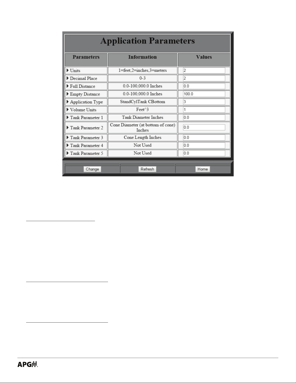
Figure 4.4
PARAMETER RANGE
Decimal Place 0 - 0
1 - 0.1
2 - 0.01
3 - 0.001
Decimal Place sets the resolution of Calc. Dist,Level,Volume (See Figure 4.5). This resolution is also used Trip
Values and Trip Windows (See Figure 4.5), and the reading on Main Display Page (See Figure 4.1).
PARAMETER RANGE
Full Distance 0 - Sensor Maximum
Full Distance sets the distance from the sensor Reference Position (See Figure 4.5) to the full level of the vessel
being monitored. Not used when Application Type is set to 0 Value.
PARAMETER RANGE
Empty Distance 0 - Sensor Maximum
Empty Distance sets the distance from the sensor Reference Position (See Figure 4.5) to the empty level of the
vessel being monitored. Not used when Application Type is set to 0 Value.
Tel: 1/888/525-7300 • Fax: 1/435/753-7490 • www.apgsensors.com • sales@apgsensors.com
17
Page 22

PARAMETER RANGE
Application Type 0 = Value (Distance)
1 = Level
2 = Volume of Standing Cylindrical Tank with or without Hemispherical Bottom
3 = Volume of Standing Cylindrical Tank with or without Conical Bottom
4 = Volume of Standing Rectangular Tank with or without Chute Bottom
5 = Volume of Horizontal Cylindrical Tank with or without Spherical Ends
6 = Volume of Spherical Tank
7 = Pounds (Linear Scaling)
8 = User Dened Units
9 = Volume of Vertical Oval Tank
10 = Volume of Horizontal Oval Tank
11 = Polynomial (strapping chart)
Application Type is used to choose the parameter conguration to convert the distance/value of Calculated
Units into Calc. Dist,Level,Volume. After selecting an Application Type and pressing “Change,” the Application
Parameters menu updates to reect the parameters of the chosen application (Compare Figure 4.3 and
Figure 4.4).
See Tank Parameters for an explaination of each Application Type and its associated parameters.
PARAMETER RANGE
Volume Units 1 = Feet3
2 = Million Feet3
3 = Gallons
4 = Meters3
5 = Liters
6 = Inches
3
7 = Barrels
Volume Units selects the units of measure for Calc. Dist,Level,Volume when a volumetric application is
selected. The settings is not used when the Application Type is set to 0, 1, 7, or 8.
Tank Parameters
Application Type Tank Parameter Function
0 - Value (Distance) Parameter 1 Not Used
Parameter 2 Not Used
Parameter 3 Not Used
Parameter 4 Not Used
Parameter 5 Not Used
Value (Distance) calculates Calc. Dist,Level,Volume using only the 4ma Value and 20ma Value settings. The result is a linear value or distance measurement.
18
Tel: 1/888/525-7300 • Fax: 1/435/753-7490 • www.apgsensors.com • sales@apgsensors.com
Page 23

Application Type Tank Parameter Function
Radius
Distance
1 - Level Parameter 1 Not Used
Parameter 2 Not Used
Parameter 3 Not Used
Parameter 4 Not Used
Parameter 5 Not Used
Level calculates Calc. Dist,Level,Volume using only the 4ma Value and 20ma Value settings, just as Value (Distance) does. The dierence is that Level allows for the denition of Full Distance and Empty Distance, which
then creates a display for percentage of level on the remote website.
Application Type Tank Parameter Function
2 - Standing Cylindrical Parameter 1 Tank Diameter
Tank with Parameter 2 Bottom Radius
Hemispherical Parameter 3 Not Used
Bottom Parameter 4 Not Used
Parameter 5 Not Used
Application Type Tank Parameter Function
3 - Standing Cylindrical Parameter 1 Tank Diameter
Tank with Parameter 2 Bottom Radius
Conical Parameter 3 Cone Length (Height)
Bottom Parameter 4 Not Used
Parameter 5 Not Used
Empty
Distance
or
Diameter
Diameter
Full
Bottom
Full
Distance
Distance
Tel: 1/888/525-7300 • Fax: 1/435/753-7490 • www.apgsensors.com • sales@apgsensors.com
Empty
Cone
Diameter
Cone
Length
19
Page 24

Application Type Tank Parameter Function
4 - Standing Rectangular Parameter 1 Tank X Dimension
Tank with Parameter 2 Tank Y Dimension
Chute Parameter 3 Chute X Dimension
Parameter 4 Chute Y Dimension
Parameter 5 Chute Length (Height)
Empty
Distance
Tank X
Full
Distance
Tank Y
Application Type Tank Parameter Function
5 - Horizontal Cylindrical Parameter 1 Tank Length
Tank with Parameter 2 Tank Diameter
Spherical Ends Parameter 3 Radius of Ends
Parameter 4 Not Used
Parameter 5 Not Used
Diameter
End
Radius
Length
Full
Distance
Empty
Distance
or
Chute
Length
Chute X
Chute Y
Application Type Tank Parameter Function
6 - Spherical Tank Parameter 1 Tank Diameter
Parameter 2 Not Used
Parameter 3 Not Used
Parameter 4 Not Used
Parameter 5 Not Used
20
Tel: 1/888/525-7300 • Fax: 1/435/753-7490 • www.apgsensors.com • sales@apgsensors.com
Empty
Distance
Diameter
Full
Distance
Page 25

Application Type Tank Parameter Function
Full
Full
7 - Pounds Parameter 1 Multiplier
(Linear Scaling) Parameter 2 Unit Denition (label)
Parameter 3 Not Used
Parameter 4 Not Used
Parameter 5 Not Used
Pounds allows for a multiplier (Parameter 1) to be applied to the Calculated Units, creating a linear scalar as
the output to Calc. Dist,Level,Volume. Such a multplier could convert the distance or level measurement of a
tank with simple geometry into a measurement of weight.
Application Type Tank Parameter Function
8 - User Dened Units Parameter 1 Not Used
Parameter 2 Unit Denition (label)
Parameter 3 Not Used
Parameter 4 Not Used
Parameter 5 Not Used
User Dened Units allows the user to set custom units for the output to Calc. Dist,Level,Volume. The label for
the custom units is stored in Parameter 2, and is applied to the the 4ma Value and 20ma Value settings, which
are used to calculate the output.
Application Type Tank Parameter Function
9 - Vertical Oval Parameter 1 Tank Length
Tank Parameter 2 Tank Depth
Parameter 3 Tank Width
Parameter 4 Not Used
Parameter 5 Not Used
Application Type Tank Parameter Function
10 - Horizontal Oval Parameter 1 Tank Length
Tank Parameter 2 Tank Depth
Parameter 3 Tank Width
Parameter 4 Not Used
Parameter 5 Not Used
Application Type Tank Parameter Function
11 - Curve Fit Polynomial Parameter 1 X^3 Coecient
(Strapping Chart) Parameter 2 X^2 Coecient
Parameter 3 X^1 Coecient
Parameter 4 X^0 Coecient
Parameter 5 Not Used
Distance
Empty
Distance
Distance
Empty
Distance
Width
Depth
Depth
Length
Length
Width
Tel: 1/888/525-7300 • Fax: 1/435/753-7490 • www.apgsensors.com • sales@apgsensors.com
21
Page 26
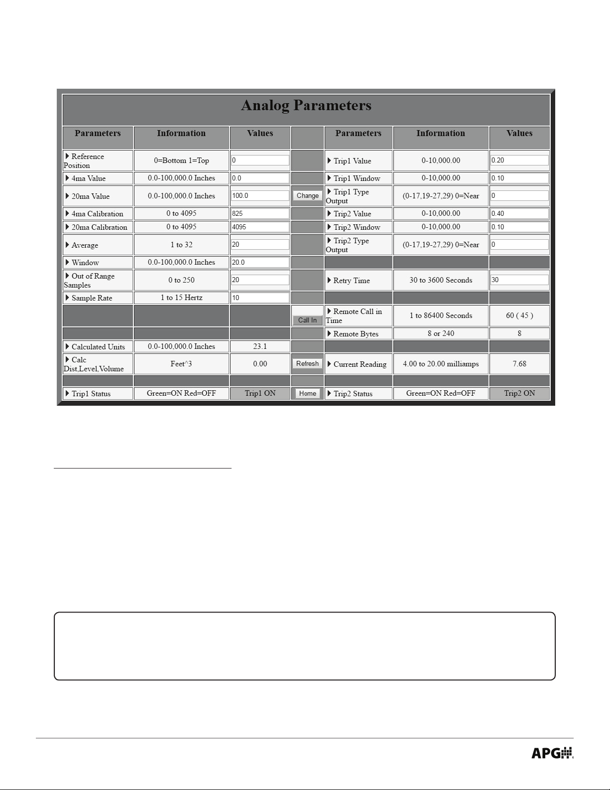
Analog Parameters
Figure 4.5
PARAMETER RANGE
Reference Position 1 = Top
0 = Bottom
0 = Not Used
Reference Position denes the zero-reference point of the sensor in relation to the vessel being monitored.
Ultrasonic sensors measure from the top down and submersible pressure transducers measure from
the bottom up. MPX magnetostrictive sensors and non-submersible pressure sensors do not use a top or
bottom reference point. Reference Position is not used when Application Type is set to 0 Value (See Figure 4.3).
IMPORTANT: Parameter values stored on the RST-5003 will not update until the
“Change” button is clicked.
22
Tel: 1/888/525-7300 • Fax: 1/435/753-7490 • www.apgsensors.com • sales@apgsensors.com
Page 27

PARAMETER RANGE
4ma Value 0 - Sensor Max Distance
4ma Value assigns the RST-5003 distance output corresponding to the output of 4 mA from the sensor.
PARAMETER RANGE
20ma Value 0 - Sensor Max Distance
20ma Value assigns RST-5003 distance output corresponding to the output of 20 mA from the sensor.
NOTE: For ultrasonic sensors only:
For Distance conguration (i.e., to interpret a greater mA output as a target surface further from sensor), set the 4ma Value to be less than the 20ma Value.
For Fill conguration (i.e., to interpret a greater mA output as a target surface closer to
sensor), set the 4ma Value to be greater than the 20ma Value. See Figure 4.6.
4 ma
Reference
Position
4mA
Value
20mA
Value
20 ma
Max.
Distance
20 ma
Reference
Position
20mA
Value
4mA
Value
4 ma
Distance
Max.
Figure 4.6
PARAMETER RANGE
4ma Calibration 0 - 4095
Default: 825
4ma Calibration ne tunes the amount of recieved signal interpreted by the RST-5003 as the 4 mA signal.
PARAMETER RANGE
20ma Calibration 0 - 4095
Default: 4095
20ma Calibration ne tunes the amount of recieved signal interpreted by the RST-5003 as the 20 mA signal.
PARAMETER RANGE
Average 1-32
Average sets the number of qualied samples to average for the displayed reading. Qualied samples are
placed in a rst-in, rst-out buer, the contents of which are averaged for Calculated Units. The larger the
number of qualied samples being averaged, the smoother the output reading will be, and the slower the
reading will be to react to quick changes.
Tel: 1/888/525-7300 • Fax: 1/435/753-7490 • www.apgsensors.com • sales@apgsensors.com
23
Page 28

PARAMETER RANGE
Example:
Window 0 - Sensor Maximum
Window determines the corresponding physical range for qualied samples, based on the current Calculated
Units. Samples beyond the +/- Window range of the current Calculated Units will not qualify unless the
average moves. Samples outside the extents of the Window are written to the Out of Range Samples buer.
(See Figure 4.7.)
PARAMETER RANGE
Out of Range Samples 0-250
Out of Range Samples sets the number of consecutive samples outside the Window necessary to
automatically adjust the current Calculated Units and move the Window.
PARAMETER RANGE
Sample Rate 1 - 15 Hz
Sample Rate is the number of samples of the sensor output taken by the RST-5003 every second.
Window = 6 Inches
Out of Range Samples = 10
All readings
Readings are rejected within
this area unless they persist
for 10 consecutive samples
Min. Reading Max. Reading
Current value of
Calculated Units
are accepted
within this area
6” 6”
Readings are rejected within
this area unless they persist
for 10 consecutive samples
Figure 4.7
Analog Calculated Displays
Figure 4.8
DISPLAY RANGE
Calculated Units Determined by Units
Calculated Units displays the “raw” reading--converted from the Current Reading (See Figure 4.15) from the
sensor, based on the 4ma Value and 20ma Value settings--using the decimal places determined by the Units
(See Figure 4.3). Calculated Units functions as the midpoint for Window.
DISPLAY RANGE
Calc. Dist,Level,Volume
Calc. Dist,Level,Volume displays the output calculated from Calculated Units using the Application Parameters
(See Figures 4.3 and 4.4). Calc. Dist,Level,Volume is the evaluation basis for Trip settings (see Figures 4.9 and
4.11) and shows as the Reading on the Main Display Page (See Figure 4.1).
24
Tel: 1/888/525-7300 • Fax: 1/435/753-7490 • www.apgsensors.com • sales@apgsensors.com
Page 29

Analog-to-SS-Relay Trip Outputs and Settings
Figure 4.9
Figure 4.10
The RST-5003 and RST-5013 have output relays that
can be congured to turn on or o based on the Calc.
Dist,Level,Volume of the sensor.
Trip Type Outputs are congured with two independent
digits: the rst for Alarm Type (Blank, 1, or 2), and the
second for Trip Condition (0-5, 7, or 9).
PARAMETER RANGE
Trip Value 0 - Sensor Max Distance
Trip Value sets the value of the primary trip position,
which is closest to the Reference Position of the sensor.
PARAMETER RANGE
Trip Window 0 - Sensor Max Distance
Trip Window sets the value from the primary trip position
to the secondary trip position, which is farther from the
sensor’s Reference Position.
REFERENCE
POSITION
TRIP
CONDITION _0
NEAR
TRIP
CONDITION _1
EXCLUSIVE
TRIP
CONDITION _2
HYSTERESIS
NEAR
TRIP
CONDITION _3
FAR
TRIP
VALUE
ON
ON
ON
OFF
TRIP
WINDOW
OFF
OFF
ON
OFF
ON
ON
OFF
Alarm Type
Blank_ - No Alarm
Designates that no alarm is to be activated or deactivated
on the remote APG-provided website (i.e., www.
levelandow.com) for the indicated Trip Condition. To
initiate only the visual Trip Status indicator (See Figure
4.10) for Trip Condition 3, Trip Type would be set to 3.
Tel: 1/888/525-7300 • Fax: 1/435/753-7490 • www.apgsensors.com • sales@apgsensors.com
TRIP
CONDITION _4
INCLUSIVE
TRIP
CONDITION _5
HYSTERESIS
FAR
OFF
OFF
Figure 4.11
ON
OFF
ON
OFF
ON
25
Page 30

Alarm Type
1_ - Active Alarm
Designates the active trip point as a web alarm condition.
To initiate web alarm whenever the Trip Condition 3 is
ON, Trip Type would be set to 13.
Alarm Type
2_ - Inactive Alarm
Designates an inactive trip point as a web alarm
condition. To initiate a web alarm whenever the Trip
Condition 3 is OFF, Trip Type would be set to 23.
Trip Condition
0 - Near
Near activates the Trip whenever the Calc.
Dist,Level,Volume is less than the Trip Value setting.
Trip Condition
1 - Exclusive
Exclusive activates the Trip whenever the Calc.
Dist,Level,Volume is less than the Trip Value setting OR
greater than the Trip Value + Trip Window settings.
Trip Condition
2 - Hysteresis Near
REFERENCE
POSITION
TRIP
CONDITION _0
NEAR
TRIP
CONDITION _1
EXCLUSIVE
TRIP
CONDITION _2
HYSTERESIS
NEAR
TRIP
CONDITION _3
FAR
TRIP
CONDITION _4
INCLUSIVE
TRIP
CONDITION _5
HYSTERESIS
FAR
TRIP
VALUE
ON
ON
ON
OFF
OFF
OFF
TRIP
WINDOW
OFF
OFF
ON
OFF
ON
ON
OFF
ON
ON
OFF
OFF
ON
Hysteresis Near activates the Trip whenever the Calc.
Figure 4.11
Dist,Level,Volume becomes less than than the Trip Value setting. The Trip remains activated until the Calc.
Dist,Level,Volume becomes greater than the Trip Value + Trip Window settings. The Trip remains o until the
Calc. Dist,Level,Volume becomes less than the Trip Value setting again.
Trip Condition
3 - Far
Far activates the Trip whenever the Calc. Dist,Level,Volume is greater than the Trip Value setting.
Trip Condition
4 - Inclusive
Inclusive activates the Trip whenever the Calc. Dist,Level,Volume is greater than the Trip Value setting AND less
than the Trip Value + Trip Window settings.
26
Tel: 1/888/525-7300 • Fax: 1/435/753-7490 • www.apgsensors.com • sales@apgsensors.com
Page 31

Trip Condition
INTERVAL TIME
5 - Hysteresis Far
Hysteresis Far activates the Trip whenever the Calc. Dist,Level,Volume becomes greater than the Trip Value +
Trip Window settings. The Trip remains activated until the Calc. Dist,Level,Volume becomes less than the Trip
Value setting. The Trip remains o until the Calc. Dist,Level,Volume becomes greater than the Trip Value + Trip
Window settings again.
Trip Condition
6 - Disable Trip
16 - Disable Relay
26 - N/A
Disable de-activates the Trip or SS Relay output.
Trip Condition
7 - Loss of Echo
Loss of Echo activates the output when the maximum calculated reading (i.e., the greater of 4ma Value and
20ma Value, see Figure 4.6) is reached.
Trip Condition
8 - Timed Interval
Timed Interval activates the output for a set amount of seconds every set amount of minutes (See Figure
4.12). When Trip Type is set to 8, Trip Value and Trip Window are changed to “Interval Time (minutes)” and
“On Time (seconds)”.
(in minutes)
“ON” TIME
(in seconds)
Relay “OFF”(open)
Figure 4.12
Trip Condition
9 - Abrupt Change
Abrupt Change activates the output whenever a user-dened maximum rate of level change (change in
distance or level divided by elapsed time) is exceeded. Trip Value denes the distance and Trip Window
denes the time.
Tel: 1/888/525-7300 • Fax: 1/435/753-7490 • www.apgsensors.com • sales@apgsensors.com
27
Page 32

Switched Input Alarms (RST-5013 and RST-5113 only)
Figure 4.13
The RST-5013 and RST-5113 have switched inputs (one and two, respectively) designed to continuously
monitor the status of a simple switch or contact closure. The RST can be congured to alarm on either an
open or closed input, and will immediately report to the remote APG-provided website, regardless of the
call-in interval, whenever an alarm condition is detected. The following are the three conguration options
for the switched input:
Input Alarm/Trip Type
18 - Closed Input Alarm
Closed Input Alarm activates the alarm when the input switch or contact closes.
Input Alarm/Trip Type
28 - Open Input Alarm
Open Input Alarm activates the alarm when the input switch or contact opens.
Input Alarm/Trip Type
30 - On Time Check Limit Alarm
On Time Check Limit Alarm will immediately report to the remote website whenever the input remains
continuously closed beyond the user specied time limit (in seconds, as set in the Trip Value parameter).
The RST will report to the website a second time once the alarm condition clears.
IMPORTANT: Inputs are NOT designed to monitor switches controlling a voltage or
electrical signal. The inputs are designed to detect continuity at the closure of un-powered contacts.
28
Tel: 1/888/525-7300 • Fax: 1/435/753-7490 • www.apgsensors.com • sales@apgsensors.com
Page 33

External Website Communication Status
Figure 4.14
The RST-5003 embedded web server includes one parameter, one button, and two status reports for
communication with the remote APG-provided website (i.e., www.levelandow.com).
PARAMETER RANGE
Retry Time 30 - 180 Seconds
Retry Time sets the time delay (in seconds) between attempts by the RST-5003 to contact the external
website.
BUTTON
Call In
Call In forces the LOE to call in to the external website.
DISPLAY RANGE
Remote Call in Time 1 - 86400 Seconds
Remote Call in Time displays the duration of the last communication between the RST-5003 and the external
website.
DISPLAY RANGE
Remote Bytes 8 or 240 Bytes
Remote Bytes displays the number of bytes of data sent in the last communication between the RST-5003
and the external website. 8 bytes indicates a normal, successful transmission. 240 bytes indicates an error
occured in the transmission.
Analog Sensor Current Reading
Figure 4.15
DISPLAY RANGE
Current Reading 4.00 - 20.00 milliamps
Current Reading displays the current 4-20 mA reading from the analog sensor. The RST converts this reading
to a distance/value measurement based on the 4ma Value and 20ma Value settings (See Figures 4.3 and 4.5).
This converted “raw” reading (Calculated Units) is the basis for the Window function, rather than the 4-20 mA
reading from the sensor (See Figure 4.7).
Tel: 1/888/525-7300 • Fax: 1/435/753-7490 • www.apgsensors.com • sales@apgsensors.com
29
Page 34
• Modbus Sensor Conguration Registers
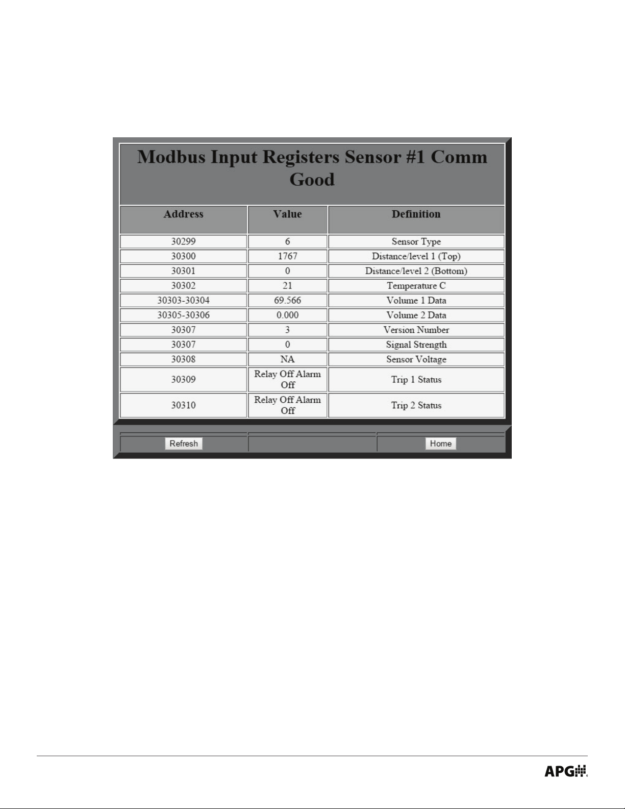
RS-485 Modbus Input Registers
Figure 4.16
This display-only menu shows the contents of the Input Registers for the selected Modbus sensor (See Figure 4.1). Registers used vary by sensor. Please see the user manual for each sensor for a full list of registers.
• Sensor Type Number and Sensor Model Number List:
Type Number Model Number Type Number Model Number
0 LOE-2126 9 PT-400/PT-500-L31 (Level)
1 LOE-6126 10 PT-400/PT-500-L5 (Pressure)
2 LOE-3136 11 DCR-1006A
3 LOE-7126 12 LPD
4 RST-5001 13 MND
5 MPX-E1/R1 (2 oats) 14 RST-5003/4
6 MPX-E1/R1 (1 oat) 15 AUS-7123
7 PG-7 16 MTM-1000
8 PG-10
Note: This list represents sensors that interface with various APG Modbus software packages. Not all inter-
face with the RST-5003.
30
Tel: 1/888/525-7300 • Fax: 1/435/753-7490 • www.apgsensors.com • sales@apgsensors.com
Page 35

RS-485 Modbus Holding 1
Figure 4.17
This menu shows the contents of the rst set of Holding Registers for the selected Modbus sensor (See
Figure 4.1). The register names and value restrictions are automatically congured for the type of sensor
detected (See Figure 4.16). Because register name and use varies by sensor, including a full breakdown of
the registers in this manual would be counterproductive. Please see the user manual for each sensor for a
full list of registers.
Tel: 1/888/525-7300 • Fax: 1/435/753-7490 • www.apgsensors.com • sales@apgsensors.com
31
Page 36

RS-485 Modbus Holding 2
Figure 4.18
This menu shows the contents of the second set of Holding Registers for the selected Modbus sensor (See
Figure 4.1). The register names and value restrictions are automatically congured for the type of sensor
detected (See Figure 4.16). Because register name and use varies by sensor, including a full breakdown of
the registers in this manual would be counterproductive. Please see the user manual for each sensor for a
full list of registers.
32
Tel: 1/888/525-7300 • Fax: 1/435/753-7490 • www.apgsensors.com • sales@apgsensors.com
Page 37
• RST-5003 Utilty Menus
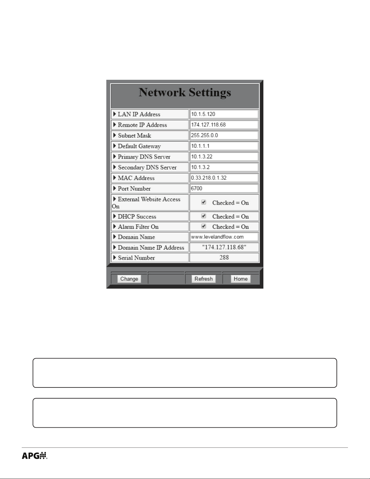
Network Settings
Figure 4.19
The Network Settings are provided for advanced users only and should not normally require changes. Each
RST ships with the DHCP enabled, which means it will automatically connect to the the APG-provided remote
website (usually www.levelandow.com) and congure its own Network Settings when plugged into a port
providing direct internet access.
NOTE: Port 6700 must be open on your local network for the RST-5003 to connect.
NOTE: Please contact APG for access to your remote access website.
Tel: 1/888/525-7300 • Fax: 1/435/753-7490 • www.apgsensors.com • sales@apgsensors.com
33
Page 38
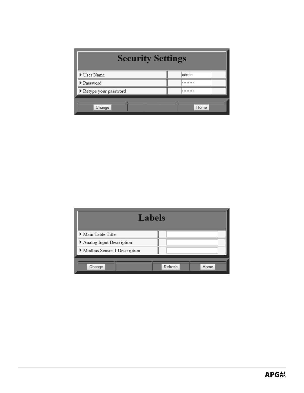
Security Settings
Figure 4.20
The Security Settings allow users to set their own user name and password for logging into the embedded
webpage.
Labels
Figure 4.21
The Labels menu allow users to create custom labels for the Main Menu and the sensors attached to the
RST-5003.
34
Tel: 1/888/525-7300 • Fax: 1/435/753-7490 • www.apgsensors.com • sales@apgsensors.com
Page 39

Figure 4.22
When labels are created in the Labels menu, they will be reected on the Main Menu page (See Figure 4.22).
RS-485 Network Settings
Figure 4.23
Tel: 1/888/525-7300 • Fax: 1/435/753-7490 • www.apgsensors.com • sales@apgsensors.com
35
Page 40

The RS-485 (Modbus) Settings menu controls the settings for the Modbus sensors (up to 10) attached to the
RST-5003.
PARAMETER RANGE
Baud Rate Checkbox 9600 Baud
Baud Rate Checkbox is used to indicate the baud rate of the of the sensors connected to the RST-5003. All
APG Modbus sensors communicate at 9600 Baud.
PARAMETER RANGE
Numb of Sensors On Line 0 - 10
Numb of Sensors On Line sets the number Modbus sensors connected to the RST-5003. This setting is not
automatically populated or updated. The user must change the setting manually. Numb of Sensors On Line
must always be equal or greater than the number of actual sensors attached to the RST-5003.
NOTE: For best results, set Numb of Sensors On Line to the highest number of num-
ber of sensor TO BE connected. No further adjustments will be needed as those sensors
are connected to the RST-5003.
PARAMETER RANGE
Sensor Number to View 1 - 10
Sensor Number to View selects number of the sensor for the RST-5003 to poll for populating the Main Menu
and for editing parameters in the Modbus Holding Register menus.
PARAMETER RANGE
New Sensor Number 0 = No Change
1 - 10
New Sensor Number changes the sensor number assigned to the sensor selected by Sensor Number to View.
IMPORTANT: When “Change” is pressed to assign a new sensor number, Sensor Num-
ber to View DOES NOT update.
PARAMETER RANGE
RS485 Sample Rate 1 - 20 Seconds
RS485 Sample Rate determines how often the RST-5003 polls the selected Modbus sensor.
36
Tel: 1/888/525-7300 • Fax: 1/435/753-7490 • www.apgsensors.com • sales@apgsensors.com
Page 41

Chapter 5: Maintenance
• General Care
Your RST-5003 series controller is very low maintenance and will need little care as long as it was installed
correctly. However, you should avoid applications for which the controller was not designed, such as
extreme temperatures, contact with incompatible corrosive chemicals and fumes, or other damaging
environments.
• Repair and Returns
Should your RST-5003 series control module require service, please contact the factory via phone, email, or
online chat. We will issue you a Return Material Authorization (RMA) number with instructions.
• Phone: 888-525-7300
• Email: sales@apgsensors.com
• Online chat at www.apgsensors.com
Please have your RST-5003’s part number and serial number available. See Warranty and Warranty
Restrictions for more information.
Tel: 1/888/525-7300 • Fax: 1/435/753-7490 • www.apgsensors.com • sales@apgsensors.com
37
Page 42

APG
R
Tel: 1/888/525-7300 • Fax: 1/435/753-7490 • www.apgsensors.com • sales@apgsensors.com
Automation Products Group, Inc.
 Loading...