

Page 1

AUT OMATION
Operator’s Manual
PRODUCTS
GROUP, INC.
PWS Series
Rotating Paddle Level Sensor
Rev . A1, 4/07
Automation Products Group, Inc.
APG...Providing tailored solutions for measurement applications
Tel: 1/888/525-7300 • Fax: 1/435/753-7490 • www.apgsensors.com • E-mail: sales@apgsensors.com
Page 2

PWS Series Rev . A1, 4/07
Table of Contents
Warranty .............................................................................................................3
Introduction ......................................................................................................4
Speci cations ....................................................................................................4
Installation .........................................................................................................5
Paddle Varieties and Dimensions ..............................................................7
Wiring ..................................................................................................................8
Start Up ............................................................................................................ 10
Maintenance ..................................................................................................11
Troubleshooting ........................................................................................... 12
Spare Parts ......................................................................................................13
Automation Products Group, Inc.
APG...Providing tailored solutions for measurement applications
2
Tel: 1/888/525-7300 • Fax: 1/435/753-7490 • www.apgsensors.com • sales@apgsensors.com
Page 3

Rev . A1, 4/07 PWS Series
• Warranty and Warranty Restrictions
APG warrants its products to be free from defects of material and workmanship
and will, without charge, replace or repair any equipment found defective
upon inspection at its factory, provided the equipment has been returned,
transportation prepaid, within 24 months from date of shipment from factory.
THE FOREGOING WARRANTY IS IN LIEU OF AND EXCLUDES
ALL OTHER WARRANTIES NOT EXPRESSLY SET FORTH HEREIN,
WHETHER EXPRESSED OR IMPLIED BY OPERATION OF LAW OR
OTHERWISE INCLUDING BUT NOT LIMITED TO ANY IMPLIED
WARRANTIES OF MERCHANTABILITY OR FITNESS FOR A
PARTICULAR PURPOSE.
No representation or warranty, express or implied, made by any sales
representative, distributor, or other agent or representative of APG which is
not specifi cally set forth herein shall be binding upon APG. APG shall not be
liable for any incidental or consequential damages, losses or expenses directly
or indirectly arising from the sale, handling, improper application or use of the
goods or from any other cause relating thereto and APG’s liability hereunder, in
any case, is expressly limited to the repair or replacement (at APG’s option) of
goods.
Warranty is specifi cally at the factory. Any on site service will be provided at
the sole expense of the Purchaser at standard fi eld service rates.
All associated equipment must be protected by properly rated electronic/
electrical protection devices. APG shall not be liable for any damage due
to improper engineering or installation by the purchaser or third parties.
Proper installation, operation and maintenance of the product becomes the
responsibility of the user upon receipt of the product.
Returns and allowances must be authorized by APG in advance. APG will
assign a Return Material Authorization (RMA) number which must appear
on all related papers and the outside of the shipping carton. All returns are
subject to the fi nal review by APG. Returns are subject to restocking charges as
determined by APG’s “Credit Return Policy”.
Automation Products Group, Inc.
APG...Providing tailored solutions for measurement applications
Tel: 1/888/525-7300 • Fax: 1/435/753-7490 • www.apgsensors.com • sales@apgsensors.com
3
Page 4

PWS Series Rev . A1, 4/07
• Introduction
The PWS rotating paddle level sensor is made speci cally for solid level
detection. The rotating paddle on the shaft is designed to detect the presence
of powders in small bins and hoppers up to 39 inches (1 m).
• Specifi cations
Operational Versions
PWS-X: Indoor model
PWS-Z: Outdoor model
PWS-XT: High Temperature
Characteristics
Detection Torque Range: 630; 560; 470; 390 g/cm (PWS-X)
500; 390; 315; 270 g/cm (PWS-Z)
Supply: 24, 100, 110, 120, 200, 240 VAC 50/60 Hz
Power Consumption: 1.5 VA
Motor Rotation: 1 rpm (50 Hz); 1.2 rpm (60 Hz)
Output Contact Rating: (SPDT): 250 V 3 A AC;
(Resistive Load) 30 V 3 A DC
Physical Attributes
Enclosure Protection: IP40 (PWS-X); IP65 (PWS-Z)
Material:
Housing: ADC and polycarbonate (PWS-X)
ADC and ABS (PWS-Z)
Mounting: Galvanized Brass
Spindle: SS304
Paddle: Polycarbonate or SS304 or SS316
Shaft Seal: PTFE washer, NBR oil seal and
molybdenum grease
Mounting: G 3/4
Automation Products Group, Inc.
APG...Providing tailored solutions for measurement applications
4
Tel: 1/888/525-7300 • Fax: 1/435/753-7490 • www.apgsensors.com • sales@apgsensors.com
Page 5
Rev . A1, 4/07 PWS Series
• Installation
Unpacking
When unpacking, do not damage the sensor with mechanical shock. After
unpacking, make sure that products you ordered are complete. If any part is
missing, wrong or damage, please contact APG.
Installation
Install the sensor in an area which meets the following conditions:
• The ambient temperature range:
- Detecting area: 14 to 160°F (-10 to +70°C)
PWS-XT: 14 to 250°F (-10 to +120°C)
- Housing: 14 to 115°F (-10 to +45°C)
• Indoor environment
• Humidity and vibration are low.
• Open container and nonhazardous area.
• Ample space for maintenance and inspection.
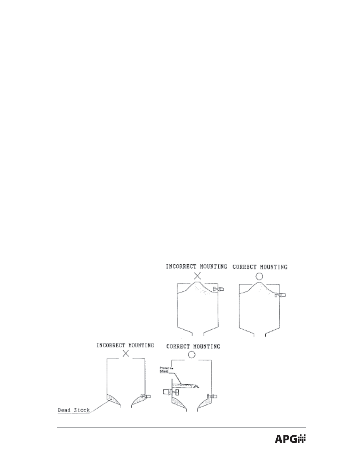
When using for high level control, pay attention to the angle of repose.
When using for low level control, prevent the PWS from being surrounded by
dead stock.
NOTE: Keep the paddle and
shaft out of the direct ow.
Failure to do this may damage
the sensor.
Caution!: To avoid burns, do
not touch the radiator n. It is
hot!
Automation Products Group, Inc.
APG...Providing tailored solutions for measurement applications
Tel: 1/888/525-7300 • Fax: 1/435/753-7490 • www.apgsensors.com • sales@apgsensors.com
5
Page 6
PWS Series Rev . A1, 4/07
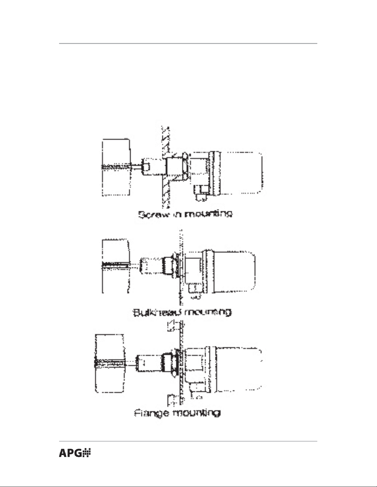
The PWS can be install using one of the following methods:
• Screw-in Mounting: Provide G 3/4” female thread.
• Bulkhead Mounting: Drill a 28 mm (1.1 in. dia.) hole. Insert and tighten
the nut, washer, and gasket.
• Flange Mounting: Use the optional JIS 5K65A sized ange.
Automation Products Group, Inc.
APG...Providing tailored solutions for measurement applications
6
Tel: 1/888/525-7300 • Fax: 1/435/753-7490 • www.apgsensors.com • sales@apgsensors.com
Page 7
Rev . A1, 4/07 PWS Series
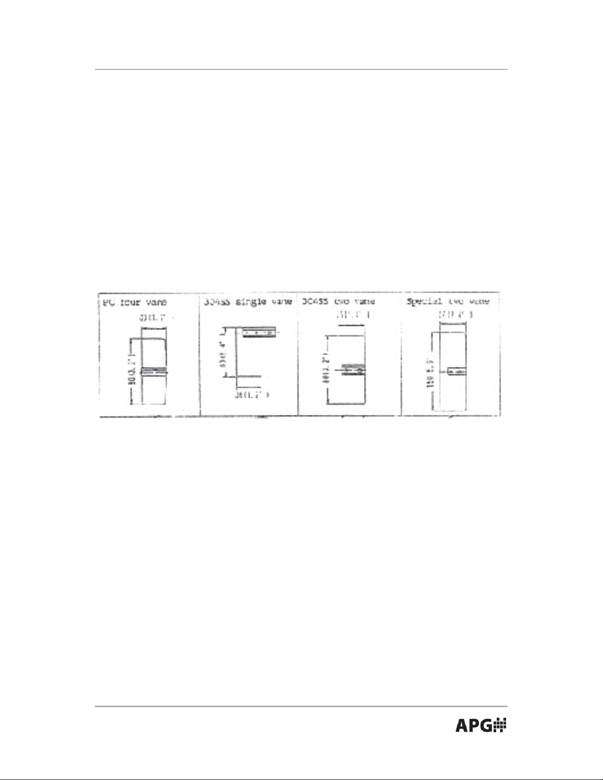
• Paddle Variety and Dimensions
The polycarbonate four vane is designed for general use on bulk density
3
as low as 0.3 g/cm
(18.7 lb./cu. ft.). Use at high and low level, top and side
mounting.
Stainless steel paddles, 304SS or 316SS, are available in one or two vane.
One vane version designed for general use on side mounting. It is suitable
3
for high density as 2.0 g/cm
(12.5 lb./cu. ft.). Especially suitable for use in high
operating temperature, model PWS-T.
Special two vane is designed for use at top or side mounting on very light
materials less the 0.02 g/cm
3
(1.25 lb./cu. ft.).
Automation Products Group, Inc.
APG...Providing tailored solutions for measurement applications
Tel: 1/888/525-7300 • Fax: 1/435/753-7490 • www.apgsensors.com • sales@apgsensors.com
7
Page 8
PWS Series Rev . A1, 4/07
PWS-Z Series (PWS-Z and PWS7-ZL)
Wiring should be in accordance with all local codes.
2
Control cable from 0.5 mm
to 3.5 mm2 is recommended.
Contact Capacity (Resistive)
250 V 3 A AC
30 V 4 A DC
Power Consumption 1.5 VA
NOTES:
1. The earth ground terminal is grounded to the housing.
2. The cable entry must be properly tted to preserve IP65 after wiring.
CAUTION: Make sure the supplying voltage and the wire color matches. The
wrong voltage or miswiring may damage the sensor.
WARNING: To avoid personal injury, DO NOT remove the housing cover
when power is applied.
Automation Products Group, Inc.
APG...Providing tailored solutions for measurement applications
8
Tel: 1/888/525-7300 • Fax: 1/435/753-7490 • www.apgsensors.com • sales@apgsensors.com
Page 9

Rev . A1, 4/07 PWS Series
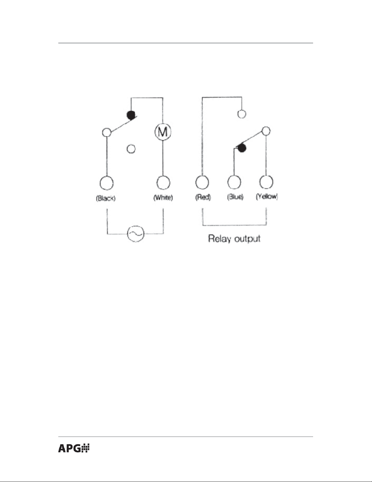
• Wiring
PWS-X Series (PWS-X, PWS-XL, and PWS-XT)
Wiring should be in accordance with all local codes. The PWS provides 5
2
cores 0.5 mm
PVC insulated cable. Install solderless terminals or sleeves to
the end of the conductors.
Contact Capacity (Resistive)
250 V 3 A AC
30 V 4 A DC
Power Consumption 1.5 VA
CAUTION: Make sure the supplying voltage and the wire color matches. The
wrong voltage or miswiring may damage the sensor.
WARNING: To avoid personal injury, DO NOT remove the housing cover
when power is applied.
Automation Products Group, Inc.
APG...Providing tailored solutions for measurement applications
Tel: 1/888/525-7300 • Fax: 1/435/753-7490 • www.apgsensors.com • sales@apgsensors.com
9
Page 10

PWS Series Rev . A1, 4/07
• Start Up
The sensitivity can be adjusted to suit diverse level control installations and
variations in material characteristics. By changing the spring position on the
set plate, the amount of torque required to signal an output can be altered.
The position may be changed by means of plier or by hand.
PWS-X Series PWS-Z Series Features
A 630 g/cm (3.5 lb./in.) 500 g/cm (2.8 lb./in.) For light or ne material
B 560 g/cm (3.1 lb./in.) 390 g/cm (2.2 lb./in.) Standard (preadjusted)
C 470 g/cm (2.6 lb./in.) 315 g/cm (1.8 lb./in.) For heavy and sticky
materials or high vibration
location.
D 390 g/cm (2.2 lb./in.) 270 g/cm (1.5 lb./in.) For heavy and sticky
materials or high vibration
location.
10
Automation Products Group, Inc.
APG...Providing tailored solutions for measurement applications
Tel: 1/888/525-7300 • Fax: 1/435/753-7490 • www.apgsensors.com • sales@apgsensors.com
Page 11

Rev . A1, 4/07 PWS Series
• Maintenance
When cleaning and checking the container, free the paddle and shaft from
deposit. The unit which detects the level of sticky materials or is installed in a
humid location must be cleaned at periodic intervals.
Tighten the housing cover and cable entry to protect the unit from rain,
splashing water, etc.
• Make sure that the power supply is turned o .
• Remove the housing cover (by turning it counterclockwise).
• Remove lead wires by melting the soldered area with a soldering iron.
• Remove the micro switch (loosen one screw).
• Install the replacement switch and tighten the screw.
• Re-solder lead wires. Refer to gure below.
• Check wiring and operation.
• Reinstall and tighten the housing cover.
Automation Products Group, Inc.
APG...Providing tailored solutions for measurement applications
Tel: 1/888/525-7300 • Fax: 1/435/753-7490 • www.apgsensors.com • sales@apgsensors.com
11
Page 12

PWS Series Rev . A1, 4/07
• Shaft and spindle is damaged.
Remedies
• Connect the power.
• Repair power supply
• Wire correctly
• Calibrate sensitivity or replace paddle
• Install sensor in good location
• Replace unit.
Symptom
Paddle is not covered by materials. Relay energized.
Possible Causes
• Insu cient power supplied.
• Miswiring
• Heavy deposit on shaft
• Material has dead stock
• Temperature too high
• Shaft is bent or damaged.
Remedies
• Connect the power.
• Repair power supply
• Wire correctly
• Calibrate sensitivity or replace paddle
• Install sensor in good location
• Replace unit.
Symptom
Relay chatters
Possible Causes
• Insu cient power supplied
• Loose cables
• Material too uid
Remedies
• Repair power supply
• Tighten connections
• Use a time delay relay.
APG...Providing tailored solutions for measurement applications
12
Tel: 1/888/525-7300 • Fax: 1/435/753-7490 • www.apgsensors.com • sales@apgsensors.com
Automation Products Group, Inc.
Page 13

Rev . A1, 4/07 PWS Series
• Troubleshooting
Symptom
Paddle is covered by material. Relay de-energized.
Possible Causes
• Power Supply not connected.
• Insu cient power supplied.
• Miswiring
• Material too light.
• Material has bridge or angle of repose.
• Spare Parts
Model Description Part Number
PWS-X-ACC-C PWS-X PC Cover 22408
PWS-X-ACC ( ) PWS-X Motor (specify voltage) On Request
PWS-X-ACC ( ) PWS-X Motor assy w/microswitch On Request
(specify voltage)
PWS-X-ACC10 PWS-X Flange, SS304, JIS 5 K 65 A 22905-0019
2 mm thick
PWS-X-ACC2 Motor (110 VAC) 22293
PWS-X-ACC3 PWS-X 4 vane (PC) paddle 22103
(80 mm dia. x 30 mm)
PWS-X-ACC4 PWS-X 1 vane (SS304) paddle 22175
(60 mm dia. x 30 mm)
PWS-X-ACC6 PWS-X2 vane (SS304) paddle 22905-0015
(150 mm dia. x 60 mm)
PWS-X-ACC7 PWS-X 2 vane (PC) paddle 22905-0016
(150 mm dia. x 60 mm)
PWS-X-ACC8 PWS-X 2 vane (SS304) paddle 22905-0017
(80 mm dia. x 35 mm)
PWS-X-ACC9 Motor Assy (110 VAC) w/ microswitch 22905-0018
Automation Products Group, Inc.
APG...Providing tailored solutions for measurement applications
Tel: 1/888/525-7300 • Fax: 1/435/753-7490 • www.apgsensors.com • sales@apgsensors.com
13
Page 14

AUT OMATION
PRODUCTS
GROUP, INC.
APG...Providing tailored solutions
for measurement applications
Automation Products Group, Inc.
Tel: 1/888/525-7300
1/435/753-7300
Fax: 1/435/753-7490
e-mail: sales@apgsensors.com
www.apgsensors.com
Automation Products Group, Inc.
1025 W. 1700 N.
Logan, UT 84321
 Loading...