

Page 1

PRODUCTS
AUT OMATION
Operator’s Manual
GROUP, INC.
PT-L1-C
Automation Products Group, Inc.
APG...Providing tailored solutions for measurement applications
Tel: 1/888/525-7300 • Fax: 1/435/753-7490 • www .apgsensors.com • E-mail: sales@apgsensors.com
Page 2

PT-L1-C Rev. A3, 10/08
T able of Content s
Warranty ......................................................................................... 3
Instructions ..................................................................................... 4
Zero Trimming ............................................................................. 4
Re-calibration .............................................................................. 4
4-20 mA Transmitter Information ............................................... 5
W iring Information ...................................................................... 6
2
APG...Providing tailored solutions for measurement applications
T el: 1/888/525-7300 • Fax: 1/435/753-7490 • www.apgsensors.com • sales@apgsensors.com
Automation Products Group, Inc.
Page 3

Rev. A3,10/08 PT-L1-C
• Warranty and Warranty Restrictions
APG warrants its products to be free from defects of material and workmanship
and will, without charge, replace or repair any equipment found defective upon
inspection at its factory, provided the equipment has been returned,
transportation prepaid, within 18 months from date of shipment from factory .
THE FOREGOING WARRANTY IS IN LIEU OF AND EXCLUDES ALL OTHER
W ARRANTIES NOT EXPRESSL Y SET FOR TH HEREIN, WHETHER
EXPRESSED OR IMPLIED BY OPERATION OF LAW OR OTHER WISE
INCLUDING BUT NOT LIMITED T O ANY IMPLIED WARRANTIES OF
MERCHANT ABILITY OR FITNESS FOR A PAR TICULAR PURPOSE.
No representation or warranty, express or implied, made by any sales
representative, distributor, or other agent or representative of APG which is not
specifically set forth herein shall be binding upon APG. APG shall not be liable
for any incidental or consequential damages, losses or expenses directly or
indirectly arising from the sale, handling, improper application or use of the
goods or from any other cause relating thereto and APG’s liability hereunder, in
any case, is expressly limited to the repair or replacement (at APG’s option) of
goods.
Warranty is specifically at the factory. Any on site service will be provided at
the sole expense of the Purchaser at standard field service rates.
All associated equipment must be protected by properly rated electronic/
electrical protection devices. APG shall not be liable for any damage due to
improper engineering or installation by the purchaser or third parties. Proper
installation, operation and maintenance of the product becomes the
responsibility of the user upon receipt of the product.
Returns and allowances must be authorized by APG in advance. APG will
assign a Return Material Authorization (RMA) number which must appear on
all related papers and the outside of the shipping carton. All returns are subject
to the final review by APG. Returns are subject to restocking charges as
determined by APG’s “Credit Return Policy”.
Automation Products Group, Inc.
APG...Providing tailored solutions for measurement applications
Tel: 1/888/525-7300 • Fax: 1/435/753-7490 • www .apgsensors.com • sales@apgsensors.com
3
Page 4
PT-L1-C Rev. A3, 10/08
• Instructions
All units are factory calibrated prior to shipment.
1. Zero Trimming
If it becomes necessary to re-adjust “zero”, this can be accomplished by
adjusting the trimpot marked “Z”. An ideal zero is indicated by an output of
4 mA.
A. Remove the knurled nut. If your transducer does not have a knurled nut,
your transducer can not be field adjusted. You can return the transducer
to the factory for repair and/or adjustment.
B. Carefully remove the connector or pigtail from the body of the transducer
and pull it all the way out so that the amplifier board is exposed. Do not
over extend the ribbon cable that attaches the amplifier board to the
sensor.
C. Reconnect the device with the loop powered circuit and have access to a
method of monitoring the output of the transducer.
D. Ensure that the transducer is at 0 psig or 0 psia (vacuum if absolute)
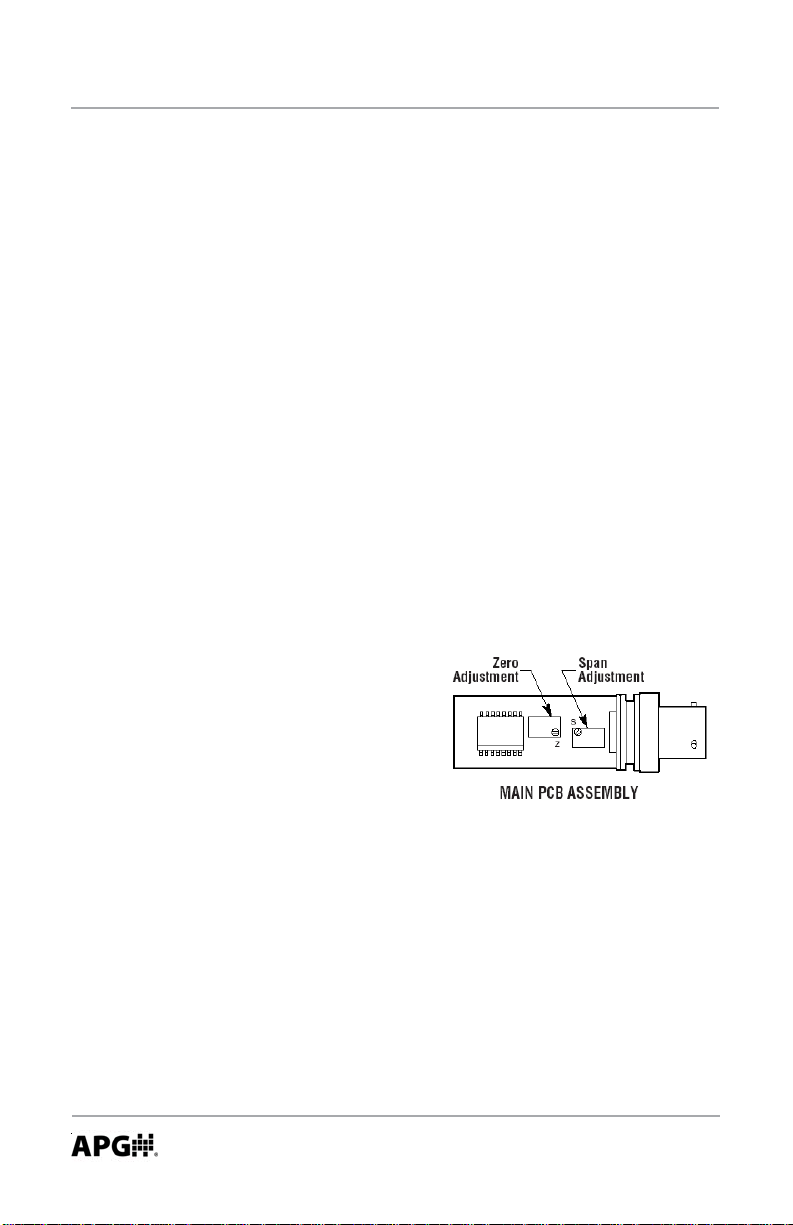
E. Using a jewelers screwdriver or a suitable instrument, adjust the “Z” pot
until you have 4 mA output. Do not
make changes to the Span
adjustment (the “S” pot to the right
of the push button) as part of the zero
trimming. The Span should only be
changed as part of the re-calibration
of a transducer with a known pressure
source.
2. Re-calibration
This procedure requires a known pressure source of at least ±0.1% accuracy
in order to fully utilize the accuracy potential of the transducer. (If not available,
you can return it to the factory for re-calibration.)
Procedure:
A. Ensure that the transducer is at 0 psig or 0 psia (vacuum if absolute), and
adjust zero as per instructions in #1.
B. Apply full scale pressure to the pressure port and adjust the span (“S”)
pot until full scale signal of 20mA is reached.
4
APG...Providing tailored solutions for measurement applications
T el: 1/888/525-7300 • Fax: 1/435/753-7490 • www.apgsensors.com • sales@apgsensors.com
Automation Products Group, Inc.
Page 5

Rev. A3,10/08 PT-L1-C
C. Re-check zero and re-adjust the zero (“Z”) pot if required.
D . Repeat steps B, and C, until no further adjustment is required.
3. 4-20 mA T ransmitter Information
This device is a 2 wire, loop powered transducer/transmitter. A voltage of
between 9 and 32 VDC must be maintained at this connection. Completion of the
earth or system ground is recommended for proper circuit protection.
Power supply voltage must be sufficient to maintain a minimum of 9 VDC at
the transducer/transmitter terminals after “dropping” voltage across RL at full
scale current (20 mA), see Figure below.. Example: If RL = 250 ohm then “drop”
is 0.02 Amps X 250 ohm = 5 volts. Therefore power supply minimum is 5 V + 9 V
= 14 V
Automation Products Group, Inc.
APG...Providing tailored solutions for measurement applications
Tel: 1/888/525-7300 • Fax: 1/435/753-7490 • www .apgsensors.com • sales@apgsensors.com
5
Page 6

PT-L1-C Rev. A3, 10/08
4. Wiring Information
Below , are the pin out diagrams, circuit diagrams, and pin out table for the
4-20 mA circuit, as needed to assist you in wiring your transducer .
N/C indicates no connection
6
APG...Providing tailored solutions for measurement applications
T el: 1/888/525-7300 • Fax: 1/435/753-7490 • www.apgsensors.com • sales@apgsensors.com
Automation Products Group, Inc.
Page 7

Rev. A3, 10/08 PT-L1-C
Notes
Automation Products Group, Inc.
APG...Providing tailored solutions for measurement applications
Tel: 1/888/525-7300 • Fax: 1/435/753-7490 • www .apgsensors.com • sales@apgsensors.com
7
Page 8

AUT OMATION
APG ...Providing tailored solutions
for measurement applications
Automation Products Group, Inc.
Tel: 1/888/525-7300
Fax: 1/435/753-7490
e-mail: sales@apgsensors.com
www.apgsensors.com
GROUP, INC.
1/435/753-7300
PRODUCTS
Automation Products Group, Inc.
1025 W. 1700 N.
Logan, UT 84321
To order additional copies of this manual, ask for APG part number PN9000047 Rev. A3, 10/08
 Loading...