

Page 1

APG
PT-405
User Manual
Explosion Proof, Heavy Duty Pressure Transmitter
Doc #9005294
R
Part #200160
Rev A2, 01/19
Page 2

Table of Contents
Introduction ................................................................................................................ iii
Warranty Statement .................................................................................................. iv
Chapter 1: Specications and Options.....................................................................1
Dimensions ........................................................................................................................................1
Specications ...................................................................................................................................2
Model Number Congurator .......................................................................................................... 3
Electrical Connectors and Pinout Table .....................................................................................4
Chapter 2: Installation and Removal Procedures and Notes .............................. 5
Tools Needed .....................................................................................................................................5
Physical Installation Notes ........................................................................................................... 5
Mounting Instructions ................................................................................................................... 5
Electrical Installation .....................................................................................................................6
Removal Instructions .....................................................................................................................6
Chapter 3: Maintenance .............................................................................................7
General Care ...................................................................................................................................... 7
Zero Trimming .................................................................................................................................. 7
Re-Calibration ................................................................................................................................... 8
Repair and Returns .......................................................................................................................... 8
Chapter 4: Hazardous Location Certication .........................................................9
CSA Certicate of Compliance .................................................................................................9-16
ii
Tel: 1/888/525-7300 • Fax: 1/435/753-7490 • www.apgsensors.com • sales@apgsensors.com
Page 3

Introduction
237484
Thank you for purchasing a Series PT-405 Explosion Proof Heavy Duty Pressure Transmitter from APG.
We appreciate your business! Please take a few minutes to familiarize yourself with your PT-405 and this
manual.
Series PT-405 pressure transmitters oer reliability over a wide range of pressures and in harsh industrial
conditions and hazardous locations. It is certied explosion proof for hazardous areas in the US and Canada
by CSA for Class 1, Division 1 environments and has a single seal for the highest safety factor. The integrated
electronics, wide operating temperature range, and durability, make the PT-405 the perfect instrument for
static and dynamic pressure measurements with an amplied output signal.
Reading your label
Every APG instrument comes with a label that includes the instrument’s model number, part number, serial
number, and a wiring pinout table. Please ensure that the part number and pinout table on your label
match your order. The following electrical ratings and approvals are also listed on the label. Please refer to
the Certicate of Compliance and Declaration of Conformity at the back of this manual for further details.
Electrical ratings
Input: 9 to 28 Volts DC; Outputs: 4-20mA / 0-5* VDC / 0-10 VDC / RS-485 (per order)
Exia Class I Division 1; Groups C, D T4
Class I, Zone 0, Group IIB
AEx d IIB T4: Ta: -40°C to 85°C
C
Ex d IIB T4: Ta: -40°C to 85°C
Single Seal.
Maximum Working Pressure: 30,000 PSI
US
PT-405-L1 (4-20mA)
Vmax Ui= 28VDC, Imax Ii = 110mA, Pmax Pi = 0.77W, Ci = 0.055μF, Li = 7.95μH
PT-405-L3/L10 (0-5* / 0-10 VDC)
Vmax Ui= 28VDC, Imax Ii = 110mA, Pmax Pi = 0.77W, Ci = 0μF, Li = 0μH
PT-405-L5/L31 (RS-485)
Vmax Ui= 28VDC, Imax Ii = 110mA, Pmax Pi = 0.77W, Ci = 0μF, Li = 0μH
*Note: 0-5 VDC includes 0.5-4.5 VDC and 1-5 VDC output ranges.
IMPORTANT: Your PT-405 MUST be installed according as indicated in Physical
Installation Notes (page 5) to meet listed approvals. Faulty installation will invalidate all
safety approvals and ratings.
Tel: 1/888/525-7300 • Fax: 1/435/753-7490 • www.apgsensors.com • sales@apgsensors.com
iii
Page 4

Warranty Statement
This product is covered by APG’s warranty to be free from defects in material and workmanship under
normal use and service of the product for 24 months. For a full explanation of our Warranty, please visit
https://www.apgsensors.com/about-us/terms-conditions. Contact Technical Support to receive a Return
Material Authorization before shipping your product back.
Scan the QR code below to read the full explanation of our Warranty on your tablet or smartphone.
iv
Tel: 1/888/525-7300 • Fax: 1/435/753-7490 • www.apgsensors.com • sales@apgsensors.com
Page 5
Chapter 1: Specications and Options
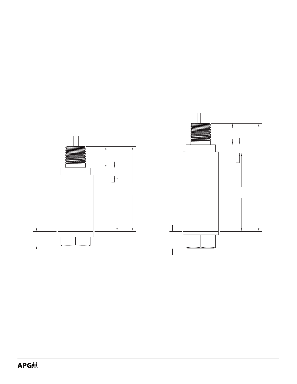
• Dimensions
0.91"
[23.05mm]
0.91"
[23.05mm]
0.35"
[8.9mm]
0.61"
[15.45mm]
0.35"
[8.9mm]
[59.7mm]
PT-405 Short Can (E60 option)
with NPTF Procces connection
Total length of PT-405 is dependant on Process Connection
2.35"
3.61"
[91.6mm]
4.59"
[116.5mm]
3.33"
[84.6mm]
0.71"
[18.1mm]
PT-405 Long Can (E60L option)
with NPTF Process Connection
Tel: 1/888/525-7300 • Fax: 1/435/753-7490 • www.apgsensors.com • sales@apgsensors.com
1
Page 6

• Specications
Performance
Pressure Ranges -15 to 30K PSI
Analog Output 4-20mA, 0-5VDC, 0.5-4.5 VDC, 1-5 VDC, 0-10VDC
Digital Output RS-485/Modbus
Over Pressure 1.5X Full Scale or limit of tting, whichever is less
Burst Pressure 3.0X Full Scale or limit of tting, whichever is less
Accuracy
Linearity, Hystereses & Repeatability ±0.25% of Full Scale (BFSL) (1% for pressure ≤ 1 psi)
Thermal Zero Shift [±0.036% FSO/°C (±0.02% FSO/°F)]
Thermal Span Shift [±0.036% FSO/°C (±0.02% FSO/°F)]
Environmental
Operating Temperature -40 to 85°C (-40 to 185°F)
Compensated Temperature -17 to 54°C (0 to 130°F)
Enclosure Protection IP65
Electrical
Supply Voltage (at sensor) 4-20 mA: 9-28 VDC
0 to 5 VDC: 9-28 VDC
0.5 to 4.5 VDC: 9-28 VDC
1 to 5 VDC: 9-28 VDC
0 to 10 VDC: 12.5-28 VDC
RS-485: 9-28 VDC
Output Signal @ 21°C 4-20 mA: 3-30 mA max.
0 to 5 VDC: 7mA max
0 to 10 VDC: 14mA max
Masterials of Construction
Wetted Materials 316L Stainless Steel ( ≤ 1,000 psi)
17-4 Stainless Steel ( > 1,000 psi)
Incoloy (10,000 - 30,000 psi)
Enclosure 316L Stainless Steel
Mechanical
Pressure Connection See model number congurator for complete list
Weight 408 - 680 g (0.9 - 1.5 lbs.)
2
Tel: 1/888/525-7300 • Fax: 1/435/753-7490 • www.apgsensors.com • sales@apgsensors.com
Page 7

• Model Number Congurator
Model Number: PT-405 - _____ - _____ - _____ - _____ - _____ - _____ - _____ - _____ - _____ - _____
A B C D E F G H I J
A. Operation / Output
□ L1▲ 4 - 20 mA output
□ L3 0 - 5 VDC output
□ L10 0 - 10 VDC output
□ L12 1 - 5 VDC output
□ L20 0.5 - 4.5 VDC output
Modbus
□ L5 RS-485 (Modbus/RTU), 4-wire
Pressure reading only
□ L31 RS-485 (Modbus/RTU), 4-wire
Level calculations, tank volume
B. Common Pressure Ranges - PSI*
□ 5 □ 50 □ 200 □ 1000 □ 5000
□ 15 □ 60 □ 300 □ 2000 □ 10000
□ 30 □ 100 □ 500 □ 3000 □ 30000
*Other ranges available. Please consult factory.
C. Units of Measure
▲
□ psi
O □ fWC □ mmH2O □ inHG
□ fH
2
□ bar □ kPa □ inH2O □ inWC
D. Pressure Type
□ A Absolute ( ≤ 200 psi)
□ S▲ Sealed ( ≤ 30,000 psi)
F. Electrical Cable Length*
□
__ Number represents length of ying leads in feet.
4-ft length required minimum. 25-ft maximum
(ex. E60-10 equals short can, 10 ft ying leads)
*Note: All cable must be in conduit.
G. Process Connection
□ P0▲ 1/4 - 18 NPTM ( ≤ 10,000 psi)
□ P1 1/2 - 14 NPTM ( ≤ 10,000 psi)
□ P5 1/4 - 18 NPTF ( ≤ 15,000 psi)
□ P6 1/2 NPTF ( ≤ 10,000 psi)
□ P38 1 1/2 in. tri-clover with 3/4 in. diaphragm ( ≤ 1,000 psi)
□ P52 1 1/2 in. NPTM ( ≤ 1,000 psi)
□ P54 7/16 - 20 UNJF-3A Male w/ Cone ( ≤ 1,000 psi)
□ P56 F250C High Pressure (10,000 psi - 30,000 psi)
□ P57 F560C40 High Pressure (10,000 psi - 30,000 psi)
H. Accuracy
1 - 5,000 PSI
□ N0*▲ ±0.25% (1% for pressure ≤ 1 psi)
□ N1* ±0.25% with NIST certication
□ N2 ±0.1% with NIST certication
□ N12 ±0.5% (required for < 500 psi)
□ N13 ±0.5% with NIST certication
*Note: ±0.25% available up to 10,000 psi for 4-20 mA output only.
Up to 30,000 PSI
□ N12 ±0.5%
□ N13 ±0.5% with NIST certication
E. Electrical Connection
□ E60 1/2 in NPTM with ying leads, short can†
□ E60L 1/2 in NPTM with ying leads, long can††
† Standard for L1, L3, L10, L12, L20. Not available for L5, L31.
†† Standard for L5, L31.
▲
This option is standard
Tel: 1/888/525-7300 • Fax: 1/435/753-7490 • www.apgsensors.com • sales@apgsensors.com
I. Materials
□ M1▲ 316L SS ( ≤ 1,000 psi)
□ M2 17-4 SS ( > 1000 psi)
□ M7 Incoloy (10,000 psi - 30,000 psi; P56/P57 only)
J. Temperature
□ S0▲ Standard: 0º - 130ºF (-17º - 54ºC)
□ S1 Extended: -40º - 180ºF (-40º - 82ºC) ( ≥ 1,000 psi)
□ S2 Extended: -40º - 250ºF (-40º - 121ºC) ( ≥ 1,000 psi)
□ S3 Extended: -30º - 170ºF (-34º - 77ºC) ( ≥ 1,000 psi)
□ S4 Extended: 0º - 185ºF (-17º - 85ºC)
3
Page 8

• Electrical Connectors, Pinout Table, and Supply Power Table
PT-405 Series Pin Out Table
4-20 mA 0-5 / 0.5-4.5 / 1-5 VDC 0-10 VDC RS-485
Red + Excitation + Excitation + Excitation + Excitation
Grn No wire + Output + Output B (Tx-)
Wht No wire - Output - Output A (Tx+)
Pigtail
Blk - Excitation - Excitation - Excitation - Excitation
Grn/
Ylw
N/C indicates no connection
For alternate pinouts, please consult factory
PT-405 Series Supply Power Table
Power Supply 9-28 VDC 9-28 VDC 12.5-28 VDC 9-28 VDC
Case
Ground
4-20 mA 0-5 / 0.5-4.5 / 1-5 VDC 0-10 VDC RS-485
Case Ground Case
Ground
Case
Ground
IMPORTANT: Some Modbus manufacturers use reversed Tx+/Tx- pins. When connect-
ing to your system, ensure A to A and B to B connections.
4
Tel: 1/888/525-7300 • Fax: 1/435/753-7490 • www.apgsensors.com • sales@apgsensors.com
Page 9

Chapter 2: Installation and Removal Procedures and Notes
• Tools Needed
• Wrench sized appropriately for your PT-405’s process connection.
• Thread tape or sealant compound for threaded connections.
• Physical Installation Notes
The PT-405 should be installed in an area--indoors or outdoors--which meets the following conditions:
• Ambient temperature between -40°C and 85°C (-40°F to +185°F)
• Relative humidity up to 100%
• Altitude up to 2000 meters (6560 feet)
• IEC-664-1 Conductive Pollution Degree 1 or 2
• IEC 61010-1 Measurement Category II
• No chemicals corrosive to stainless steel (such as NH3, SO2, Cl2 etc.)
• Ample space for maintenance and inspection
• Explosion proof conduit, with seal installed within 18 inches, must be used for cable connection to PT-
405.
• Class II power supply
IMPORTANT: Incorrectly connecting your PT-405 Pressure Transmitter to explosion
proof conduit, or using unapproved conduit, will void the protection rating of your PT-405.
• Mounting Instructions
Mounting your pressure transducer is easy if you follow a few simple steps:
• Never over-tighten the sensor. This can compress the diaphragm, changing how it reacts to pressure.
In all cases, tighten the sensor as little as possible to create an adequate seal. On straight threads,
tighten only until you feel the o-ring compress - making sure you don’t damage or extrude the o-ring.
• Always use thread tape or sealant compound on tapered threads. Wrap thread tape in the opposite
direction of the threads so it does not unravel as you screw the sensor into place. Unraveling can cause
uneven distribution and seal failure. For straight threads use an o-ring.
• Always start screwing in your sensor by hand to avoid cross-threading. Thread failure can be a problem
if you damage threads by over-tightening them or by crossing threads.
Tel: 1/888/525-7300 • Fax: 1/435/753-7490 • www.apgsensors.com • sales@apgsensors.com
5
Page 10

• Electrical Installation
• Check the pinout table on your PT-405 against your order.
• Check that your electrical system wiring matches the pinout table on your PT-405.
• Connect cable from PT-405 to your control system.
DANGER: Incorrectly connecting your PT-405 Pressure Transmitter to your control
system could result in injury or death.
• Removal Instructions
Removing your PT-405 from service must be done with care. It’s easy to create an unsafe situation, or
damage your sensor, if you are not careful to follow these guidelines:
• Make sure the pressure is completely removed from the line or vessel where your sensor is installed.
Follow any and all procedures for safely isolating any media contained inside the line or vessel.
• Remove the sensor with an appropriately sized wrench (per your process connection).
• Clean the sensor’s tting and diaphragm of any debris (see General Care) and inspect for damage.
• Store your sensor in a dry place, at a temperature between -40° F and 180° F.
DANGER: Removing your PT-405 Pressure Transmitter while there is still pressure in
the line could result in injury or death.
6
Tel: 1/888/525-7300 • Fax: 1/435/753-7490 • www.apgsensors.com • sales@apgsensors.com
Page 11

Chapter 3: Maintenance
• General Care
Your PT-405 series pressure transmitter is very low maintenance and will need little care as long as it is
installed correctly. However, in general, you should:
• Keep the transmitter and the area around it generally clean.
• Avoid applications for which the transmitter was not designed, such as extreme temperatures, contact
with incompatible corrosive chemicals, or other damaging environments.
• Inspect the threads whenever you remove the transmitter from duty or change its location.
• Avoid touching the diaphragm. Contact with the diaphragm, especially with a tool, could permanently
shift the output and ruin accuracy.
• Clean the diaphragm or the diaphragm bore with extreme care. If using a tool is required, make sure it
does not touch the diaphragm.
• Zero Trimming
• Remove unit from Hazardous Location prior to performing Zero Trimming procedure.
• Remove the protective screw.
• Ensure that the transmitter is at 0 psig or 0 psia (vacuum if absolute). For compound ranges, i.e., -15
psi to 30 psi, the 4 mA, 0 V, 0.5 V, or 1 V set point is also at vacuum.
• Using a jeweler’s screwdriver or a suitable instrument, adjust the “Z” pot until you have a 4 mA, 0 V,
0.5 V, or 1 V output.
IMPORTANT: Do not make changes to the Span adjustment (the “S” pot to the right,
see Figure 3.1) as part of the zero trimming. The Span should only be changed as part of
the recalibration of a gauge with a known pressure source.
Zero & Span
Adjustment
Figure 3.1
Tel: 1/888/525-7300 • Fax: 1/435/753-7490 • www.apgsensors.com • sales@apgsensors.com
7
Page 12

• Re-Calibration
This procedure requires a known pressure source of at least ±0.1% accuracy in order to fully utilize the
accuracy potential of the PT-405. (If not available, you can return it to the factory for re-calibration.)
• Remove unit from Hazardous Location prior to recalibration.
• Ensure that the transducer is at 0 psig or 0 psia (vacuum if absolute), and adjust zero as per instruc-
tions for zero trimming.
• Apply full scale pressure to the pressure port and adjust the Span (“S”) pot (on the right of Figure 3.1)
until the full scale signal is reached.
• Re-check zero and re-adjust the zero (“Z”) pot if required
• Repeat previous two steps until no further adjustment is required.
NOTE: You may also return the PT-405 to the factory for repair and/or adjustment.
IMPORTANT: Do not adjust Zero or Span potentiometer while your PT-405 is installed
in a Hazardous Location. Removing the protective screws to access the potentiometers
invalidates the Hazardous Location approvals until they are replaced.
• Repair and Returns
Should your PT-405 series pressure transmitter require service, please contact the factory via phone, email,
or online chat. We will issue you a Return Material Authorization (RMA) number with instructions.
• Phone: 888-525-7300
• Email: sales@apgsensors.com
• Online chat at www.apgsensors.com
Please have your PT-405’s part number and serial number available. See Terms & Conditions (https://www.
apgsensors.com/about-us/terms-conditions) for more information.
8
Tel: 1/888/525-7300 • Fax: 1/435/753-7490 • www.apgsensors.com • sales@apgsensors.com
Page 13
Chapter 4: Hazardous Location Installation and Certication
• CSA Certicate of Compliance
Certificate of Compliance
Certificate: 1984045 Master Contract: 237484 (237484)
Project: 70159942 Date Issued: 2018-03-29
Issued to: Automation Products Group Inc
1025 West 1700 North
Logan, Utah 84321
USA
Attention: Joseph James
The products listed below are eligible to bear the CSA Mark shown
with adjacent indicators 'C' and 'US' for Canada and US or with adjacent
indicator 'US' for US only or without either indicator for Canada only.
Issued by:
PRODUCTS
CLASS 2258 03 - Process Control Equipment - Intrinsically Safe and Non Incendive systems - For Hazardous
Locations
CLASS 2258 83 - Process Control Equipment - Intrinsically Safe and Non Incendive systems - For Hazardous
Locations - Certified to US Standards
Class I, Div. 2, Groups C and D
Class I, Zone 2, Group IIB
Ex nL IIB T4; -40°C ≤ Ta ≤ +85°C
AEx nC IIB T4; -40°C ≤ Ta ≤ +85°C
Model PT-400-L1xxxx Pressure Transmitter. Rated 9-28VDC, 4-20mA; Maximum Ambient 85° C;
Temperature Code T4; Maximum Working Pressure 10,000 PSI. Enclosure type: IP65. Installed as per
Drawing 9002794. Single Seal. Non-Incendive with the following Entity Parameters:
Vmax, Ui = 28V
Imax, Ii = 110mA
Pmax, Pi = 0.77W
Ci = 0.055µF
Li = 7.95µH
DQD 507 Rev. 2016-02-18 Page 1
Tel: 1/888/525-7300 • Fax: 1/435/753-7490 • www.apgsensors.com • sales@apgsensors.com
Albert Jansen
Albert Jansen
9
Page 14

Certificate:
Project:
1984045
70159942
Master Contract: 237484
Date Issued: 2018-03-29
Model PT-400-L3/L10xxxx Pressure Transmitter. Rated 9-28VDC, 0-5V, 20mA or 0-10V, 20mA;
Maximum Ambient 85° C; Temperature Code T4; Maximum Working Pressure 10,000 PSI. Installed as
per Drawing 9002794. Single Seal. Non-Incendive with the following Entity Parameters:
Vmax, Ui = 28V
Imax, Ii = 110mA
Pmax, Pi = 0.77W
Ci = 0µF
Li = 0µH
Model PT-500-xxxx Pressure Transmitter, Rated 10-28VDC, 4-20mA; Maximum Ambient 85° C;
Temperature Code T4; Maximum Working Pressure 10,000 PSI; Single Seal. Non-Incendive with the
following Entity Parameters:
Vmax, Ui = 28V
Imax, Ii = 110mA
Pmax, Pi = 0.77W
Ci = 0µF
Li = 0µH
Conditions of Acceptability: PT-400, PT-500
1. The "x" in the Model designations may be any alpha-numeric character, to denote minor mechanical options,
not affecting safety.
2. These devices must be connected to a suitably certified and approved apparatus that provides non-incendive
outputs either equal to or less than those as indicated by the applicable control drawings. This certified apparatus
must be located in a safe area.
3. The equipment must be connected to a certified class 2 power supply
10
DQD 507 Rev. 2016-02-18 Page 2
Tel: 1/888/525-7300 • Fax: 1/435/753-7490 • www.apgsensors.com • sales@apgsensors.com
Page 15

Certificate:
Project:
1984045
70159942
Master Contract: 237484
Date Issued: 2018-03-29
CLASS 2258 04 - Process Control Equipment - Intrinsically Safe, Entity - For Hazardous Locations
CLASS 2258 84 - Process Control Equipment - Intrinsically Safe, Entity - For Hazardous Locations - Certified to
US Standards
Class I, Div. 1, Groups C, D
Class I, Zone 0, Group IIB
Ex ia IIB T4; -40°C ≤ Ta ≤ +85°C,
AEx ia IIB T4; -40°C ≤ Ta ≤ +85°C,
Model PT-400-L1xxxx Pressure Transmitter. Rated 9-28VDC, 4-20mA. Maximum Working Pressure:
10,000 PSI. Installed as per Drawing 9002794. Ambient Range: -40°C to +85°C. Enclosure type: IP65.
Single Seal. Intrinsically safe with the following entity parameters:
Vmax, Ui = 28V
Imax, Ii = 110mA
Pmax, Pi = 0.77W
Ci = 0.055µF
Li = 7.95µH
Model PT-500-xxxx Pressure Transmitter; Maximum Ambient 85° C; Temperature Code T4; Maximum
Working Pressure 10,000 PSI; Single Seal. Entity parameters as follows:
Vmax, Ui = 28V
Imax, Ii = 110mA
Pmax, Pi = 0.77W
Ci = 0.042µF
Li = 0.320µH
Conditions of Acceptability: PT-400, PT-500
1. The "x" in the Model designations may be any alpha-numeric character, to denote minor mechanical options,
not affecting safety.
2. These devices must be connected to a NRTL approved safety barrier (located in a safe area).
3. The equipment must be connected to a certified class 2 power supply
DQD 507 Rev. 2016-02-18 Page 3
Tel: 1/888/525-7300 • Fax: 1/435/753-7490 • www.apgsensors.com • sales@apgsensors.com
11
Page 16

Certificate:
Project:
1984045
70159942
Master Contract: 237484
Date Issued: 2018-03-29
CLASS 2258 02 - Process Control Equipment - For Hazardous Locations
CLASS 2258 82 - Process Control Equipment - For Hazardous Locations - Certified to US Standards
Class I Div. 1 Groups C and D
Model PT-405-xxxxxxxxx Pressure Transmitter. Rated 9-28V
, 4-20mA. Maximum working pressure (MEMS):
DC
1,000 psi). Maximum working pressure (Foil): 30,000psi. Ambient Range: -40°C to +85°C. Single Seal.
Conditions of Acceptability
1. The equipment must be connected to a certified class 2 power supply
2. The conduit connected to the equipment must be sealed within 18 inches of the equipment enclosure.
3. The "x" in the model designation may be any alpha-numeric character, to denote minor mechanical or
electrical options, not affecting safety.
12
DQD 507 Rev. 2016-02-18 Page 4
Tel: 1/888/525-7300 • Fax: 1/435/753-7490 • www.apgsensors.com • sales@apgsensors.com
Page 17

Certificate:
Project:
C22.2 No 0 - M1991
General Requirements - Canadian Electrical Code Part II.
Bonding and Grounding of Electrical Equipment (Protective
Grounding).
C22.2 No. 30 – M1986
Explosion-proof enclosures for use in Class I hazardous locations
Intrinsically Safe and Non-Incendive Equipment for Use in Hazardous
Locations.
Non-Incendive Electrical Equipment for Use in Class I, Division 2
Hazardous Locations.
CAN/CSA-C22.2 No. 60079-0:11
Explosive Atmospheres - Part 0: Equipment - General requirements
Explosive Atmospheres – Part 11: Equipment protection by intrinsic
safety "i"
Electrical apparatus for explosive gas atmospheres - Part 15:
apparatus
CAN/CSA-C22.2 No. 60529:05
Degrees of protection provided by enclosures (IP Code)
Safety requirements for electrical equipment for measurement, control,
and laboratory use — Part 1: General requirements
UL 508, 17th Edition
Industrial Control Equipment.
Intrinsically Safe Apparatus and Associated Apparatus for use in Class
I, II, III, Division 1, Hazardous (Classified) Locations.
Explosion-Proof and Dust-Ignition-Proof Electrical Equipment for Use
in Hazardous (Classified) Locations
Electrical Equipment For Measurement, Control, and Laboratory Use;
Part 1: General Requirements
Nonincendive Electrical Equipment for Use in Class I and II, Division 2
and Class III, Divisions 1 and 2 Hazardous (Classified) Locations
Requirements for Process Sealing Between Electrical Systems and
Flammable or Combustible Process Fluids
Electrical Apparatus for Explosive Gas Atmospheres - Part 0: General
Electrical apparatus for Explosive Gas Atmospheres - Part 11: Intrinsic
Electrical apparatus for Explosive Gas Atmospheres - Part 15: Type of
ANSI/IEC 60529:2004
Degrees of Protection Provided by Enclosures (IP Code)
1984045
70159942
Master Contract: 237484
Date Issued: 2018-03-29
APPLICABLE REQUIREMENTS
C22.2 No 0.4 - M2004
C22.2 No 157 - M1992
C22.2 No 213 - M1987
CAN/CSA-C22.2 No. 60079-11:11
CAN/CSA-C22.2 No. 60079-15:12
CAN/CSA-C22.2 No. 61010-1-12
UL 913, 7Th Edition
UL 1203, 5th Edition
UL 61010-1
ANSI/ISA-12.12.01-2007
ANSI/ISA-12.27-01-2003
ANSI/UL 60079-0:09
ANSI/UL 60079-11:09
ANSI/UL 60079-15:09
Construction, test and marking of type of protection “n” electrical
Requirements
Safety “i”
Protection “n”
DQD 507 Rev. 2016-02-18 Page 5
Tel: 1/888/525-7300 • Fax: 1/435/753-7490 • www.apgsensors.com • sales@apgsensors.com
13
Page 18

Certificate:
Project:
Class I, Division 2, Groups C and D
AEx nC IIB T4; -40°C ≤ Ta ≤ +85°C
Class I, Division 1, Groups C,D
AEx ia IIB T4; -40°C ≤ Ta ≤ +85°C
Class I, Division 1, Groups C and D
1984045
70159942
Master Contract: 237484
Date Issued: 2018-03-29
MARKINGS
The manufacturer is required to apply the following markings:
Products shall be marked with the markings specified by the particular product standard.
Products certified for Canada shall have all Caution and Warning markings in both English and French.
Additional bilingual markings not covered by the product standard(s) may be required by the Authorities Having
Jurisdiction. It is the responsibility of the manufacturer to provide and apply these additional markings, where
applicable, in accordance with the requirements of those authorities.
The products listed are eligible to bear the CSA Mark shown with adjacent indicators 'C' and 'US' for Canada and
US (indicating that products have been manufactured to the requirements of both Canadian and U.S. Standards) or
with adjacent indicator 'US' for US only or without either indicator for Canada only.
The following markings must appear on the PT-400-xxxx and PT-500-xxxx as applicable.
1) Submitter's name, trademark, or the CSA file number (adjacent to the CSA Mark).
2) Catalogue / Model designation.
3) Complete electrical rating (Entity parameters).
4) Date code / Serial number traceable to month and year of manufacture.
5) Hazardous Location designations.
Class I, Zone 2, Group IIB
Ex nL IIB T4; -40°C ≤ Ta ≤ +85°C
Class I, Zone 0, Group IIB
Ex ia IIB T4; -40°C ≤ Ta ≤ +85°C
6) The symbol "Ex ia".
7) The words "INTRINSICALLY SAFE / SECURITE INTRINSEQUE".
8) Temperature code T4
9) Maximum ambient 85°C
10) The CSA Mark with the “c” and “us” qualifiers.
11) Reference to the installation drawings
12) The marking “Single Seal”
13) The following bilingual cautions: (May be located on the installation drawing)
WARNING: SUBSTITUTION OF COMPONENTS MAY IMPAIR INTRINSIC SAFETY: and,
AVERTISSEMENT: LA SUBSTITUTION DE COMPOSANTS PEUT COMPROMETTRE LA SECURITE
INTRINSEQUE".
14) The warning: “Must be connected to a Class 2 power supply”
The following markings must appear on the PT-405-xxxxxxxxx as applicable.
1) Submitter's name, trademark, or the CSA file number (adjacent to the CSA Mark).
2) Catalogue / Model designation.
3) Complete electrical rating
4) Date code / Serial number traceable to month and year of manufacture.
5) Hazardous Location designations.
6) Temperature code T4
7) Minimum ambient -40, ,maximum ambient 85°C
8) The CSA Mark with the “c” and “us” qualifiers.
9) Reference to the installation drawings
The marking “Single Seal”
DQD 507 Rev. 2016-02-18 Page 6
14
Tel: 1/888/525-7300 • Fax: 1/435/753-7490 • www.apgsensors.com • sales@apgsensors.com
Page 19

Certificate:
Project:
1984045
70159942
Master Contract: 237484
Date Issued: 2018-03-29
10) The warnings
1.
EXPLOSION HAZARD – ENSURE SET SCREWS ARE FULLY TIGHTENED, AND DO NOT
DISCONNECT OR CALIBRATE EQUIPMENT, UNLESS POWER HAS BEEN SWITCHED OFF OR AREA
IS KNOWN TO BE NON-HAZARDOUS.
2. SEAL WITHIN 18”
3. Must be connected to a Class 2 power supply
DQD 507 Rev. 2016-02-18 Page 7
Tel: 1/888/525-7300 • Fax: 1/435/753-7490 • www.apgsensors.com • sales@apgsensors.com
15
Page 20

Certificate:
Project:
Project
Date Description
70159942
2018
Update CSA 142 to 61010 3rd Ed. 2. Add new explosionproof model PT-405
fo
PT-405, and PT-500.
2587208
2012-12-17
Update to include revised documentation.
2517306
2012-08-22
Update to include revised schematics for the PT400-L1xxxx pressure sensor.
1984045
2008
PT
Intrinsically Safe and Non-Incendive
1984045
70159942
Master Contract: 237484
Date Issued: 2018-03-29
Supplement to Certificate of Compliance
Certificate: 1984045 Master Contract: 237484 (237484)
The products listed, including the latest revision described below,
are eligible to be marked in accordance with the referenced Certificate.
Product Certification History
-03-29
r Class I, Division 1, Groups C&D. Add “Single Seal” marking to PT-400,
-03-04
-400 and PT-500 Pressure Transducers for use in Hazardous Locations as
DQD 507 Rev. 2016-02-18 Page 8
16
Tel: 1/888/525-7300 • Fax: 1/435/753-7490 • www.apgsensors.com • sales@apgsensors.com
Page 21

Tel: 1/888/525-7300 • Fax: 1/435/753-7490 • www.apgsensors.com • sales@apgsensors.com
17
Page 22

APG
R
Tel: 1/888/525-7300 • Fax: 1/435/753-7490 • www.apgsensors.com • sales@apgsensors.com
Automation Products Group, Inc.
 Loading...