

Page 1

AUT OMATION
Operator’s Manual
PRODUCTS
GROUP, INC.
PG10
Full Access
DOC. 9003470
Rev B 6/11
Automation Products Group, Inc.
APG...Providing tailored solutions for measurement applications
Tel: 1/888/525-7300 • Fax: 1/435/753-7490 • www.apgsensors.com • E-mail: sales@apgsensors.com
Page 2

PG10 Rev. B, 6/11
Table of Contents
Warranty ................................................................................................................3
Programming the PG10 ....................................................................................4-32
Menu Flow Chart................................................................................................5
Mode Setting ......................................................................................................6
Accessing/Exiting the Setup Menu ....................................................................7
Maximum/Minimum Function .............................................................................8
Units of Measure ................................................................................................9
Using Custom Units ...................................................................................10
Peak-Hold Feature ........................................................................................... 11
Advanced Settings ......................................................................................12-17
Auto-Off .......................................................................................................12
Decimal Place .............................................................................................13
Sample Rate ............................................................................................... 14
Bar Graph ...................................................................................................15
Range Adjustment.......................................................................................16
Quick Calibration.........................................................................................17
Datalogging .................................................................................................18-25
Date & Time ................................................................................................19
Logging Sample Rate .................................................................................20
Event Logging .............................................................................................22
Viewing Logged Readings ..........................................................................24
Enabling/Disabling the Clock ......................................................................25
Tare Feature.....................................................................................................26
Default..............................................................................................................27
Outputs .......................................................................................................28-32
Analog Outputs ......................................................................................28-29
Trip Point Outputs ..................................................................................30-32
Communications Settings: ..........................................................................33-36
Wiring .............................................................................................................37-39
Specifi cations .................................................................................................40-41
Automation Products Group, Inc.
APG...Providing tailored solutions for measurement applications
2
Tel: 1/888/525-7300 • Fax: 1/435/753-7490 • www.apgsensors.com • sales@apgsensors.com
Page 3

Rev. B, 6/11 PG10
• Warranty and Warranty Restrictions
APG warrants its products to be free from defects of material and workmanship
and will, without charge, replace or repair any equipment found defective
upon inspection at its factory, provided the equipment has been returned,
transportation prepaid, within 24 months from date of shipment from factory.
THE FOREGOING WARRANTY IS IN LIEU OF AND EXCLUDES
ALL OTHER WARRANTIES NOT EXPRESSLY SET FORTH HEREIN,
WHETHER EXPRESSED OR IMPLIED BY OPERATION OF LAW OR
OTHERWISE INCLUDING BUT NOT LIMITED TO ANY IMPLIED
WARRANTIES OF MERCHANTABILITY OR FITNESS FOR A
PARTICULAR PURPOSE.
No representation or warranty, express or implied, made by any sales
representative, distributor, or other agent or representative of APG which is
not specifi cally set forth herein shall be binding upon APG. APG shall not be
liable for any incidental or consequential damages, losses or expenses directly
or indirectly arising from the sale, handling, improper application or use of the
goods or from any other cause relating thereto and APG’s liability hereunder, in
any case, is expressly limited to the repair or replacement (at APG’s option) of
goods.
Warranty is specifi cally at the factory. Any on site service will be provided at
the sole expense of the Purchaser at standard fi eld service rates.
All associated equipment must be protected by properly rated electronic/
electrical protection devices. APG shall not be liable for any damage due
to improper engineering or installation by the purchaser or third parties.
Proper installation, operation and maintenance of the product becomes the
responsibility of the user upon receipt of the product.
Returns and allowances must be authorized by APG in advance. APG will
assign a Return Material Authorization (RMA) number which must appear
on all related papers and the outside of the shipping carton. All returns are
subject to the fi nal review by APG. Returns are subject to restocking charges as
determined by APG’s “Credit Return Policy”.
Automation Products Group, Inc.
APG...Providing tailored solutions for measurement applications
Tel: 1/888/525-7300 • Fax: 1/435/753-7490 • www.apgsensors.com • sales@apgsensors.com
3
Page 4
PG10 Rev. B, 6/11
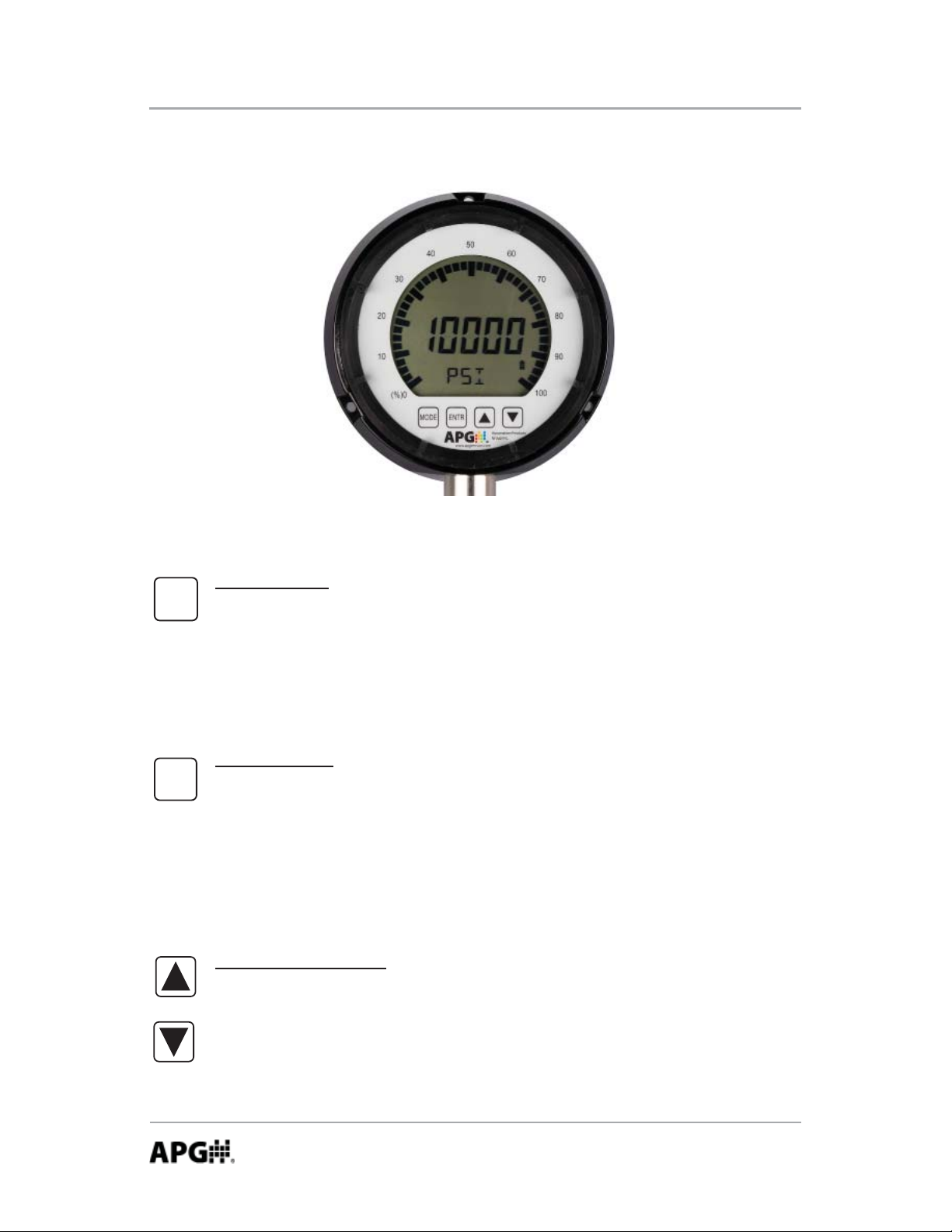
Programming the PG10
Each of the 4 buttons on the PG10 performs dual functions; one within the setup
menu system, and another when in standard operating mode.
MODE
ENTR
Mode Button
Primary Function: Used to access the main setup menu or to return to
the main setup menu from any of the submenus.
Secondary Function: Used to cycle the gauge on and off by pressing and
holding for approximately 2 seconds.
Enter Button
Primary Function: Used to accept the value displayed within each menu
setting.
Secondary Function: Used to Zero the gauge or Tare the gauge (when
the tare feature is enabled) by pressing and holding for approximately 3
seconds.
Up & Down Arrows
Primary Function: Used to cycle through all options and settings within
the menu system.
Secondary Function: Used to cycle between the Minimum, Maximum
and the present pressure reading.
Automation Products Group, Inc.
APG...Providing tailored solutions for measurement applications
4
Tel: 1/888/525-7300 • Fax: 1/435/753-7490 • www.apgsensors.com • sales@apgsensors.com
Page 5
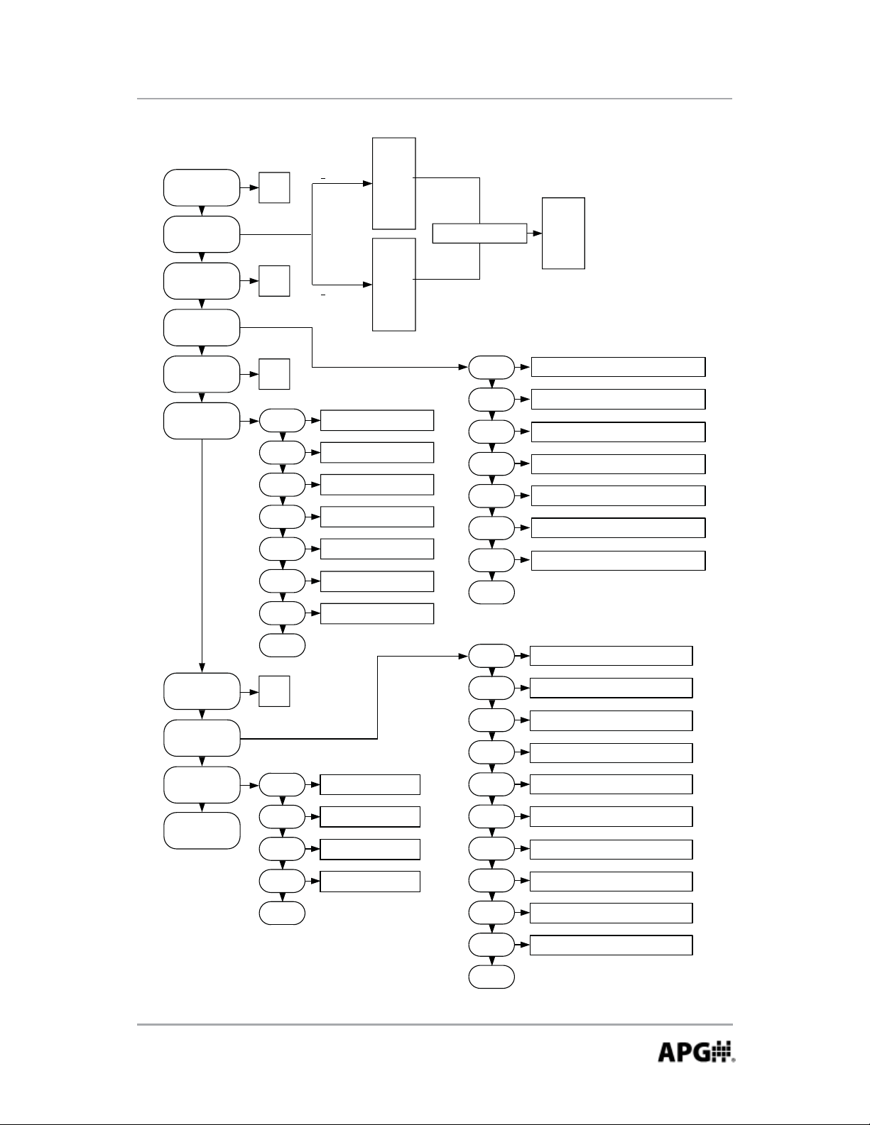
Rev. B, 6/11 PG10
PSI
BAR
KPA
MAXMIN
UNITS
P HOLD
ADVSET
YES
NO
ON
OFF
<
120 PSI
>
120 PSI
CUSTOM
MBAR
INH
MMHG
CUSTOM
KGCM
FTH
CMHG
INHG
PSI
BAR
KPA
MPA
2
O
2
O
2
CUSTOM ONLY
CUSTOM ONLY
SET MULTIPLIER VALUE
LBF
KN
LBS
NEWTON
TON
TONNES
TARE
DATLOG
DEFAULT
OUTPUT
ON
OFF
DATE
TIME
SAMPLE
LOG
EVENT
VIEW
CLOCK
EXIT
YES
NO
SET DATE MM.DD.YY
SET TIME HR:MIN:SEC
1s, 30s, 1m, 30m, 1hr, 1day
ŽŶƟŶƵŽƵƐǀĞŶƚ^ƚŽƉůĞĂƌ
T1ON, T2ON, T1OFF, T2OFF,
T1T2ON, T1T2OFF
VIEW LOGGED SAMPLES
ON, OFF
AUTO
DEC PL
SAMPLE
BAR 0
BAR100
RANGE
CALIBR
EXIT
AL SET
AH SET
AL CAL
AH CAL
OFF, 2MIN, 4MIN, 8MIN, 16MIN, 32MIN, LIGHT
HI RES, MED RES, LO RES
SLOW, MEDIUM, FAST
SET BAR GRAPH 0%
SET BAR GRAPH 100%
SET RANGE
FAST CALIBRATE, ZERO AND SPAN
SET ANALOG LOW PRESSURE
SET ANALOG HIGH PRESSURE
SET ANALOG LOW CALIBRATION
SET ANALOG HIGH CALIBRATION
COMM
BAUD R
PARITY
2400, 9600, 19200, 33400
NONE, EVEN, ODD
T1TYPE
T1PRES
TYPE0, TYPE1, TYPE2, TYPE3, TYPE4, TYPE5
SET TRIP 1 PRESSURE
EXIT
STOPBT
SENNU
EXIT
M
SET SENSOR NUMBER
1 STOP, 2 STOP
T1WIN
T2TYPE
T2PRES
T2WIN
EXIT
SET TRIP 1 WINDOW
TYPE0, TYPE1, TYPE2, TYPE3, TYPE4, TYPE5
SET TRIP 1 PRESSURE
SET TRIP 1 WINDOW
Automation Products Group, Inc.
APG...Providing tailored solutions for measurement applications
Tel: 1/888/525-7300 • Fax: 1/435/753-7490 • www.apgsensors.com • sales@apgsensors.com
5
Page 6
PG10 Rev. B, 6/11
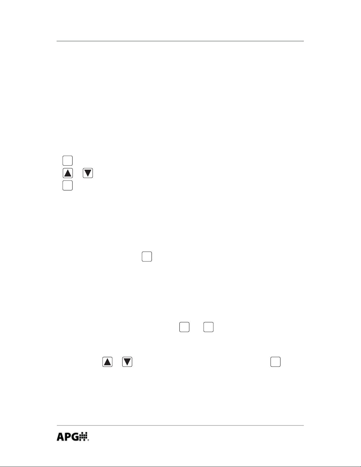
• Operating Modes:
The PG10 has 4 standard operating modes to choose from:
Mode 000: Full Access
- Provides access to all menu settings. If no buttons are pushed for 1 minute,
the gauge will revert back to Mode 003 (factory default).
Mode 002: Limited Access
- Menu is locked.
ENTR
- zeros the reading (press and hold for 3 seconds).
- or cycles between the Max and Min readings.
MODE
- On/Off functions only on battery powered gauges.
Mode 003: Factory Default
- Full access except Full Scale Calibration is locked.
Mode 005: Locked Access
- All buttons locked except will power on/off battery powered gauges.
MODE
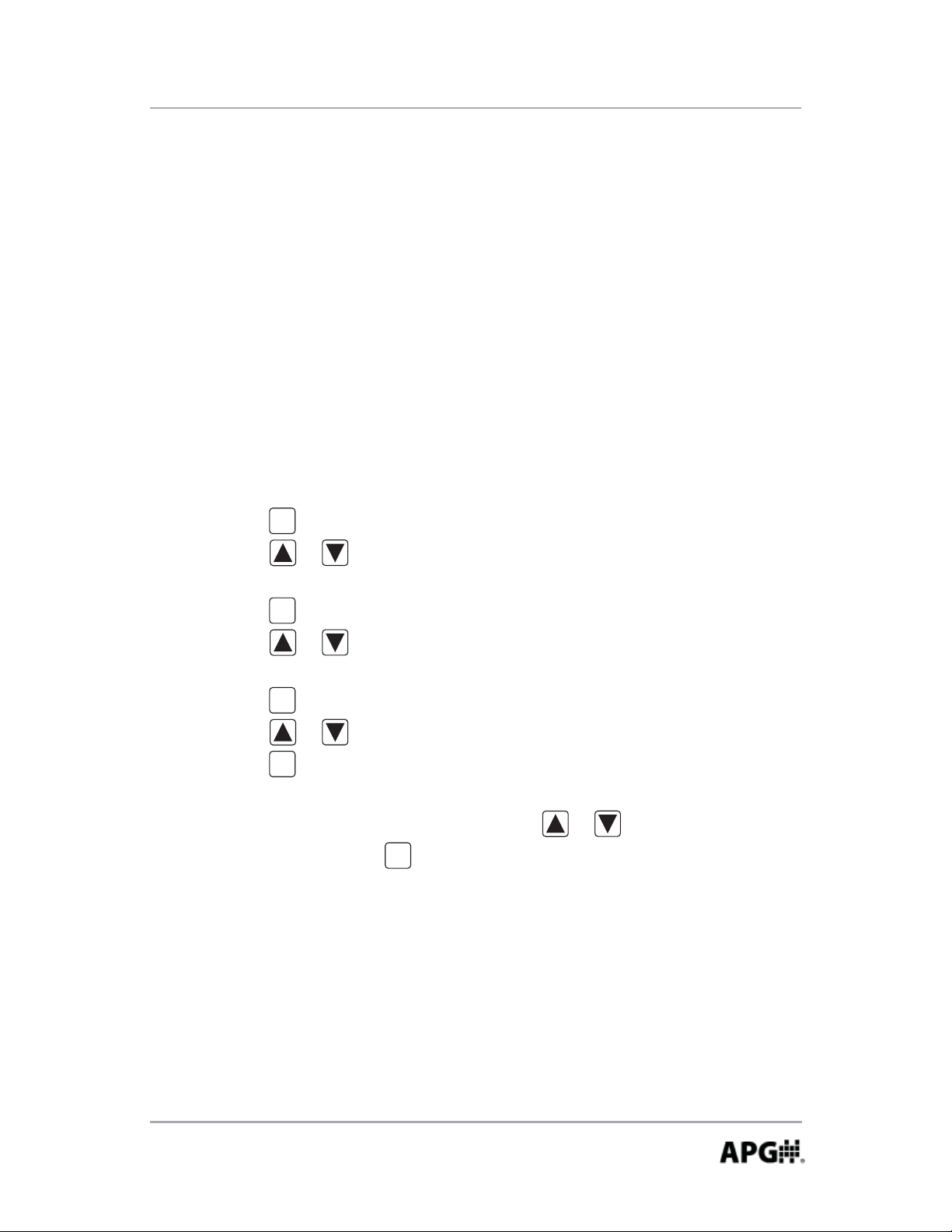
Accessing the Operating Mode Setting:
Step 1: Simultaneously press and hold and for approximately
MODE
3 seconds. This will bring up the 3 digit mode number.
Step 2: Enter the desired mode number (see Operating Modes above) by
using or to change the value of the fl ashing digit, and
to accept the value and advance to the next digit.
ENTR
ENTR
Automation Products Group, Inc.
APG...Providing tailored solutions for measurement applications
6
Tel: 1/888/525-7300 • Fax: 1/435/753-7490 • www.apgsensors.com • sales@apgsensors.com
Page 7
Rev. B, 6/11 PG10
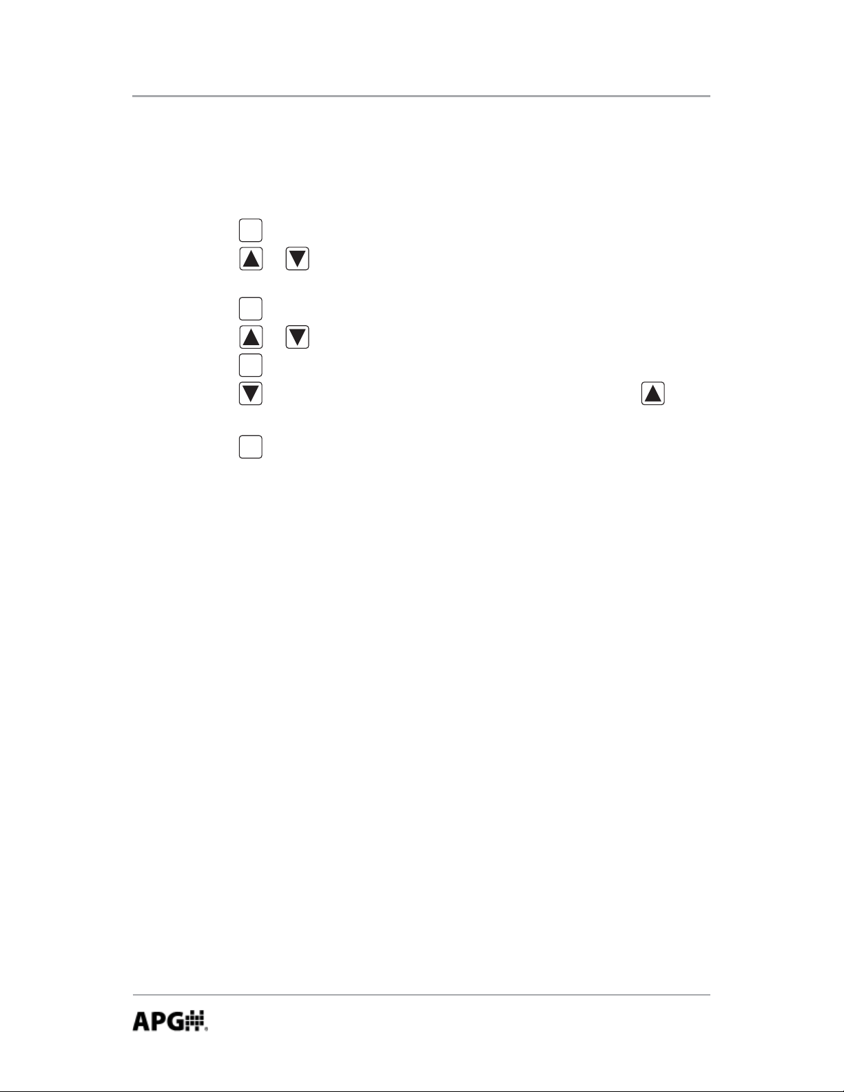
Accessing the Setup Menu:
Step 1: Simultaneously press and hold and for approximately 3
MODE
ENTR
seconds. This will bring up the 3 digit mode number.
Step 2: Using or to change the value of the fl ashing digit, and
ENTR
to advance to the next digit, change the mode number to 000.
Step 3: Press to enter the setup menu, and press or to scroll
MODE
through menu choices.
Exiting the Menu System:
Step 1: While in the main setup menu, press or until EXIT is
displayed.
Step 2: Press to exit the menu system.
ENTR
Automation Products Group, Inc.
APG...Providing tailored solutions for measurement applications
Tel: 1/888/525-7300 • Fax: 1/435/753-7490 • www.apgsensors.com • sales@apgsensors.com
7
Page 8
PG10 Rev. B, 6/11
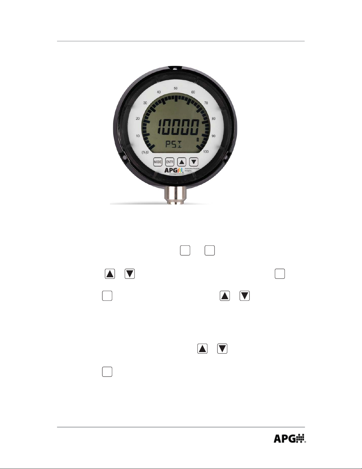
• Maximum/Minimum Reset (MAXMIN):
Pressing the or button while in operating mode will cycle between
displaying the present pressure reading, the maximum pressure reading and
the minimum pressure reading. The maximum and minimum readings will be
stored until the gauge is powered down or the max/min readings are reset.
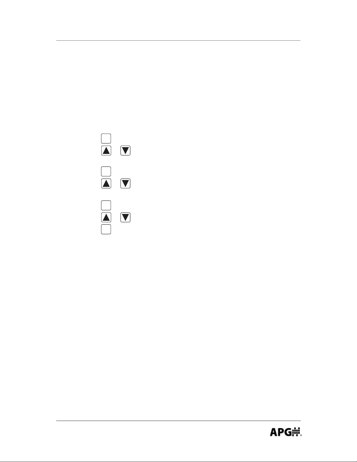
Resetting the Max/Min readings:
Step 1: Press once to enter the main setup menu.
MODE
Step 2: Press or cycle through the options until MAXMIN is
displayed.
Step 3: Press to access the Max/Min reset options.
ENTR
Step 4: Press or to toggle between YES and NO until YES is
displayed.
Step 5: Press to reset the Max/Min readings and return to the main setup
ENTR
menu.
Automation Products Group, Inc.
APG...Providing tailored solutions for measurement applications
8
Tel: 1/888/525-7300 • Fax: 1/435/753-7490 • www.apgsensors.com • sales@apgsensors.com
Page 9

Rev. B, 6/11 PG10
• Units of Measure (UNITS):
Allows the user to select the unit of measure to be displayed as the pressure
reading.
Options:
For gauges over 120 psi:
PSI (pounds per square inch)
bAR (bar)
KPA (kilopascals)
*CUSTOM (see “Using Custom Units” on next page)
KGCM^2 (kilograms per cubic centimeter)
MPA (megapascals)
FTH20 (feet of water @ 60 F)
cmHG (centimeters of mercury)
For gauges less than 120 psi:
PSI (pounds per square inch)
bAR (bar)
KPA (kilopascals)
*CUSTOM (see “Using Custom Units” on next page)
mbAR (millibar)
INHG (inches of mercury)
INH20 (inches of water @ 60 F)
mmHG (millimeters of mercury)
Setting the Unit of Measure:
Step 1: Press once to enter the main setup menu.
MODE
Step 2: Press or to cycle through the options until UNITS is displayed.
Step 3: Press to access the Units options.
ENTR
Step 4: Press or to cycle through setting options until the desired unit
of measure is displayed.
Step 5: Press to apply the setting and return to the main setup menu.
APG...Providing tailored solutions for measurement applications
Tel: 1/888/525-7300 • Fax: 1/435/753-7490 • www.apgsensors.com • sales@apgsensors.com
ENTR
Automation Products Group, Inc.
9
Page 10
PG10 Rev. B, 6/11
Using Custom Units (CUSTOM):
The Custom Units setting allows the user to display a volumetric weight by
applying a conversion factor to the pressure reading.
NOTE: The conversion factor must be calculated using PSI as the base unit of
measure.
Setting the Custom Units feature:
Step 1: Calculate the conversion factor from psi to the desired unit of measure.
Step 2: Press once to enter the main setup menu.
MODE
Step 3: Press or to cycle through the options until UNITS is displayed.
Step 4: Press to access the Units setting options.
ENTR
Step 5: Press or to cycle through the Units options until CUSTOM is
displayed.
Step 6: Press to access the Custom Units setting. A 5-digit conversion
ENTR
factor will appear with the fi rst digit fl ashing.
Step 7: Press or to change the value of the fl ashing digit.
Step 8: Press to accept the fl ashing digit and advance to the next
ENTR
digit......repeat steps 7 and 8 as necessary.
Step 9: After the last digit is accepted by pressing , use or
ENTR
scroll through the custom units of measure; LBF, KN, LBS, KG,
NEWTON, TON, TONNES.
Step 10: Press to accept the custom unit.
ENTR
Step 11: Press or to shift the decimal point position.
Step 12: Press to accept the decimal point position and return to the main
ENTR
setup menu.
10
Automation Products Group, Inc.
APG...Providing tailored solutions for measurement applications
Tel: 1/888/525-7300 • Fax: 1/435/753-7490 • www.apgsensors.com • sales@apgsensors.com
Page 11
Rev. B, 6/11 PG10
• Peak-Hold (P HOLd):
When the Peak-Hold is enabled, the gauge will display the “peak” or maximum
pressure reading since the gauge was powered on or the Max/Min value was
reset.
NOTE 1: When the Peak-Hold feature is enabled, the icon will be
PEAK
displayed in the upper left area of the display.
Options: Off or On
Enabling the Peak-Hold feature:
Step 1: Press to enter the main setup menu.
MODE
Step 2: Press or to cycle through the options until P HOLd is displayed.
Step 3: Press to access the Peak-Hold setting options.
ENTR
Step 4: Press or to toggle between OFF and ON.
Step 5: Press to apply the displayed setting and return to main setup menu.
ENTR
NOTE 2: The peak value can be reset by pressing
Automation Products Group, Inc.
APG...Providing tailored solutions for measurement applications
Tel: 1/888/525-7300 • Fax: 1/435/753-7490 • www.apgsensors.com • sales@apgsensors.com
11
Page 12
PG10 Rev. B, 6/11
• Advanced Settings (AdVSET):
The Advanced Settings menu is used to customize the LCD display and to setup
any optional features, such as an analog output.
Auto-Off (AUTO):
This function is applicable to battery powered units only. The Auto-Off feature
allows the user to designate the time of inactivity (no buttons pushed) until the
gauge automatically powers down.
Options: OFF, 2 MIN, 4 MIN, 8 MIN, 16 MIN, 32 MIN and LIGHT
NOTE 1: Selecting OFF disables the Auto-Off feature; the gauge will then
remain powered indefi nitely so long as suffi cient voltage is being supplied
(>1.8V).
NOTE 2: Selecting LIGHT will keep the gauge continuously powered as
long as the light sensor in the PG10 detects adequate light levels. When the
environment is suffi ciently dark, the PG10 will automatically shut down until
the lighting once again reaches the threshold of the light sensor.
Setting the Auto-Off feature:
Step 1: Press to enter the main setup menu.
MODE
Step 2: Press or to cycle through the menu options until AdVSET is
displayed.
Step 3: Press to enter the Advanced Settings menu.
ENTR
Step 4: Press or to cycle through the menu options until AUTO is
displayed.
Step 5: Press to access the Auto-Off setting options.
ENTR
Step 6: Press or to cycle through setting options until the desired
setting is displayed.
Step 7: Press to apply the setting and return to advanced setup menu.
ENTR
Step 8: To exit the advanced setup menu, press or until EXIT is
displayed and press to exit to the main setup menu.
APG...Providing tailored solutions for measurement applications
12
Tel: 1/888/525-7300 • Fax: 1/435/753-7490 • www.apgsensors.com • sales@apgsensors.com
ENTR
Automation Products Group, Inc.
Page 13
Rev. B, 6/11 PG10
Decimal Place (dEC PL):
The reading can be set to display in High Resolution (HI RES), Medium
Resolution (MEdRES) or Low Resolution (LO RES) mode. Switching between
resolutions will shift the displayed reading by one decimal place position.
NOTE: Gauges without a decimal place position will display a dummy zero (or
zeros) when the resolution is changed to medium or low.
Options: HI RES (high resolution), MEdRES (medium resolution) or LO RES
(low resolution)
Setting the Decimal Place feature:
Step 1: Press to enter the main setup menu.
MODE
Step 2: Press or to cycle through the options until AdVSET is
displayed.
Step 3: Press to enter the Advanced Settings menu.
ENTR
Step 4: Press or to cycle through the options until dEC PL is
displayed.
Step 5: Press to access the Decimal Place setting options.
ENTR
Step 6: Press or to cycle through the resolution settings.
Step 7: Press to apply the displayed setting and return to advanced setup
ENTR
menu.
Step 8: To exit the advanced setup menu, press or until EXIT is
displayed and press to exit to the main setup menu.
ENTR
Automation Products Group, Inc.
APG...Providing tailored solutions for measurement applications
Tel: 1/888/525-7300 • Fax: 1/435/753-7490 • www.apgsensors.com • sales@apgsensors.com
13
Page 14

PG10 Rev. B, 6/11
Sample Rate (SAMPLE):
Adjusts the rate at which the gauge takes sample readings.
NOTE: Setting the Sample Rate to “SLOW” will help preserve battery life
(when applicable) and will also help to smooth rapidly fl uctuating
readings.
Options: SLOW (4x/second), MEdIUM (8x/second), FAST (16x/second)
Setting the Sample Rate feature:
Step 1: Press to enter the main setup menu.
MODE
Step 2: Press or to cycle through the options until AdVSET is
displayed.
Step 3: Press to access the Advanced Settings menu.
ENTR
Step 4: Press or to cycle through the options until SAMPLE is
displayed.
Step 5: Press to access the Sample Rate setting options.
ENTR
Step 6: Press or to cycle through the setting options until the desired
setting is displayed.
Step 7: Press to apply the displayed setting and return to advanced setup
ENTR
menu.
Step 8: To exit the advanced setup menu, press or until EXIT is
displayed and press to exit to the main setup menu.
ENTR
14
Automation Products Group, Inc.
APG...Providing tailored solutions for measurement applications
Tel: 1/888/525-7300 • Fax: 1/435/753-7490 • www.apgsensors.com • sales@apgsensors.com
Page 15

Rev. B, 6/11 PG10
Bar Graph 0% (bAR 0) & Bar Graph 100% (bAR100) Settings:
Allows the user to defi ne the reading values associated with 0% and 100% on
0
the 270
display bar graph. Bars will appear/disappear in 10% increments of the
total span between the two values.
NOTE: The 0% reference does not have to be the lower pressure setting;
0% can be set as the higher pressure setting, thereby causing the bar graph to
increase as the pressure decreases. Negative pressure settings can also be used
as either the 0% or 100% reference points.
Setting the Display Bar Graph:
Step 1: Press once to enter the main setup menu.
MODE
Step 2: Press or to cycle through the options until AdVSET is
displayed.
Step 3: Press to access the Advanced Settings menu.
ENTR
Step 4: Press or to cycle through the options until BAR 0 is displayed.
Step 5: Press to access the Bar Graph 0% value. A 5-digit number will
ENTR
appear with the fi rst digit fl ashing.
Step 6: Press or to change the value of the fi rst fl ashing digit.
Step 7: Press to accept the value of the fl ashing digit and advance to the
ENTR
next digit......repeat steps 6 and 7 until the desired 0% reading is fully
entered.
Step 8: Press or to cycle through the options until BAR100 is displayed.
Step 9: Repeat Steps 5-7 to enter the Bar Graph 100% value.
Step 10: To exit the advanced setup menu, press or until EXIT is
displayed and press to exit to the main setup menu.
ENTR
Automation Products Group, Inc.
APG...Providing tailored solutions for measurement applications
Tel: 1/888/525-7300 • Fax: 1/435/753-7490 • www.apgsensors.com • sales@apgsensors.com
15
Page 16

PG10 Rev. B, 6/11
Full-Scale Range Adjust (RANGE):
Allows the user to adjust the reading at full-scale pressure. The reading can be
adjusted by +/-10% full-scale.
NOTE: The pressure reading must be within 5% of the full-scale value in order
to make Range adjustments. For example, a 1000 psi gauge would need
to be reading between 950 psi and 1050 psi in order to adjust the Range
feature. If the reading is not within 5% of full scale, NOAdJU (No
Adjustment) will be displayed when trying to adjust the Range.
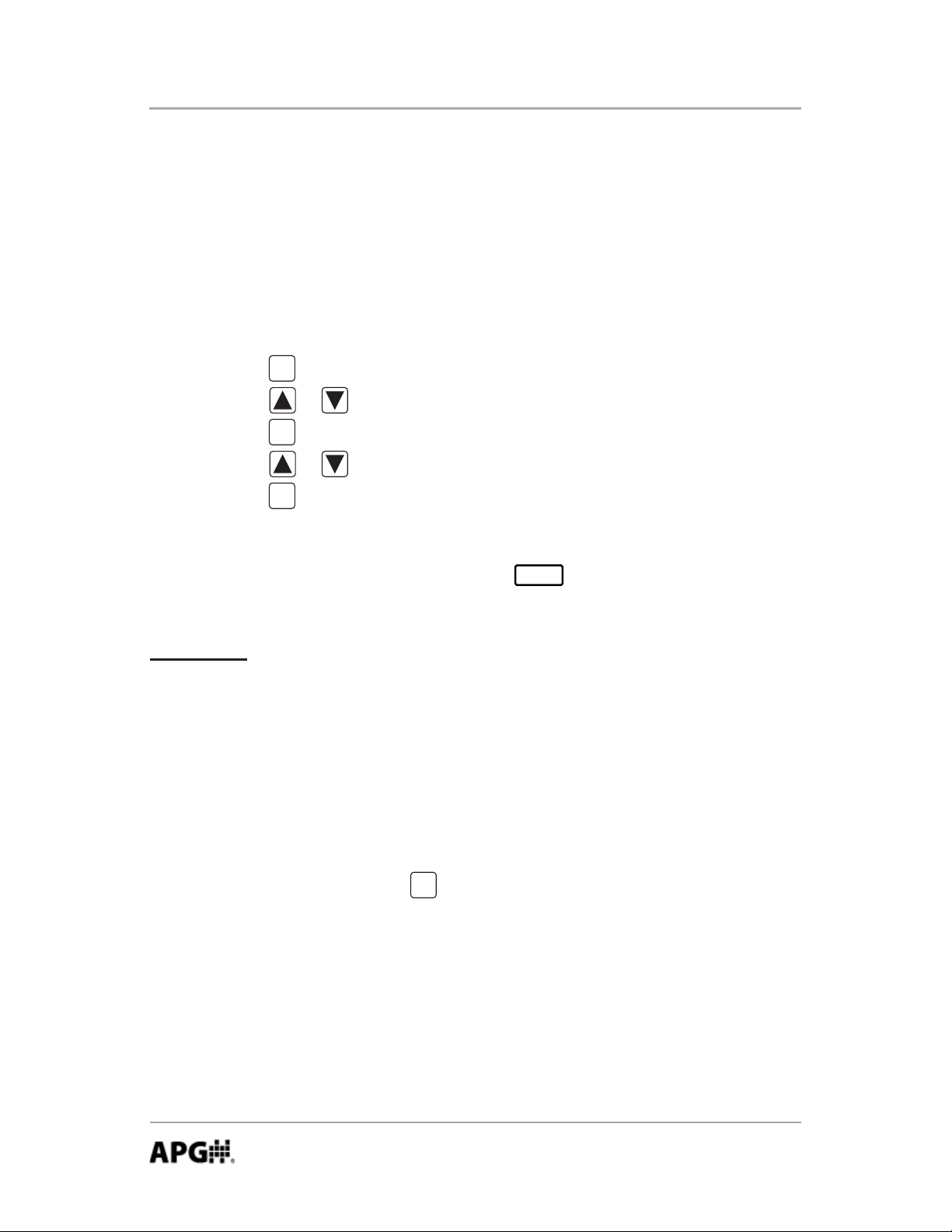
Adjusting the Full-Scale Range:
Step 1: Ensure that the pressure reading is within 5% of full-scale.
Step 2: Press to enter the main setup menu.
MODE
Step 3: Press or to cycle through the options until AdVSET is
displayed.
Step 4: Press to access the Advanced Settings menu.
ENTR
Step 5: Press or to cycle through the options until RANGE is displayed.
Step 6: Press to enter the Range adjust mode.
ENTR
Step 7: Press to increase the reading, or press to decrease the reading.
Step 8: Press to accept the adjusted reading and return to the advanced
MODE
setup menu.
Step 9: To exit the Advanced Setup menu, press or until EXIT is
displayed and press to exit to the main setup menu.
ENTR
16
Automation Products Group, Inc.
APG...Providing tailored solutions for measurement applications
Tel: 1/888/525-7300 • Fax: 1/435/753-7490 • www.apgsensors.com • sales@apgsensors.com
Page 17

Rev. B, 6/11 PG10
Fast Calibration (CALIBR):
Allows the user to perform a fast calibration of the zero and span.
NOTE: Both zero pressure and full-scale pressure must be applied to the gauge
in order to complete the quick calibration process.
Step 1: Press to enter the main setup menu.
MODE
Step 2: Press or to cycle through the menu options until AdVSET is
displayed.
Step 3: Press to enter the Advanced Settings menu.
ENTR
Step 4: Press or to cycle through the options until CALIBR is
displayed.
Step 5: Press to access the CALIBR mode. The gauge will display the
ENTR
word ZERO, prompting the user to perform the zero pressure quick
calibration.
Step 6: Ensure no pressure is applied to the gauge. Press to zero the gauge.
The gauge will then display the word SPAN, prompting the user to
perform the full-scale pressure quick calibration.
Step 7: Apply full pressure to the gauge and press to complete the quick
ENTR
calibration and return to advanced setup menu.
Step 9: To exit the advanced setup menu, press or until EXIT is
displayed and press to exit to the main setup menu.
ENTR
Automation Products Group, Inc.
APG...Providing tailored solutions for measurement applications
Tel: 1/888/525-7300 • Fax: 1/435/753-7490 • www.apgsensors.com • sales@apgsensors.com
17
Page 18

PG10 Rev. B, 6/11
• Datalogging (dATLOG):
When datalogging is enabled, the PG10 will log the pressure readings, along
with the associated date/time stamps, at an interval determined by the Logging
Sample Rate setting (see page 20).
The PG10 can be confi gured to log continuously, based solely on the Logging
Sample Rate setting, or to log only when user defi ned pressure conditions exist
(event logging). The gauge will continue to log readings at the Logging Sample
Rate interval for as long as the event conditions persist.
The gauge can store a maximum of 60 records. Each record is logged in
a FIFO (fi rst-in, fi rst-out) buffer. This means that once the buffer is full (60
records), the oldest record will be overwritten by the next logged reading.
18
Automation Products Group, Inc.
APG...Providing tailored solutions for measurement applications
Tel: 1/888/525-7300 • Fax: 1/435/753-7490 • www.apgsensors.com • sales@apgsensors.com
Page 19

Rev. B, 6/11 PG10
Date (DATE) and Time (TIME):
Used to set the date and time, which will be used as the reference for the time
stamp of the logged readings.
NOTE: Hours are set using the 24 hour system (e.g. 1:00 p.m. is 13:00).
Step 1: Press to enter the main setup menu.
MODE
Step 2: Press or to cycle through the menu options until dATLOG is
displayed.
Step 3: Press to enter the Datalogging menu options.
ENTR
Step 4: Press or to cycle through the menu options until DATE is
displayed.
Step 5: Press to access the Date settings. A 2-digit month number will
ENTR
appear with the fi rst digit fl ashing.
Step 6: Press or to cycle the fi rst digit, and to accept the value
ENTR
and advance to the second digit. Repeat the same process for
the second digit and press to accept and advance to the day of the
ENTR
month setting, which will appear with the fi rst digit fl ashing.
Repeat the process one last time by entering the year.
Step 7: Press to apply the setting and return to Datalogging menu.
ENTR
Step 8: Press or to cycle through the menu options until TIME is
displayed.
Step 9: Press to access the time settings. Repeat the process used to set the
ENTR
date to set the time (hour, minute, seconds).
Automation Products Group, Inc.
APG...Providing tailored solutions for measurement applications
Tel: 1/888/525-7300 • Fax: 1/435/753-7490 • www.apgsensors.com • sales@apgsensors.com
19
Page 20

PG10 Rev. B, 6/11
Logging Sample Rate (SAMPLE):
Determine the interval between logged readings whenever logging is activated.
Options: 1 second (1s), 30 seconds (30s), 1 minute (1m), 30 minutes (30m),
1 hour (1h), and 1 day (1day).
Setting the Logging Sample Rate:
Step 1: Press to enter the main setup menu.
MODE
Step 2: Press or to cycle through the options until dATLOG is
displayed.
Step 3: Press to enter the Datalogging menu.
ENTR
Step 4: Press or to cycle through the options until SAMPLE is
displayed.
Step 5: Press to access the Logging Sample Rate setting options.
ENTR
Step 6: Press or to cycle through the sample rate settings.
Step 7: Press to apply the displayed setting and return to Datalogging
ENTR
menu.
20
Automation Products Group, Inc.
APG...Providing tailored solutions for measurement applications
Tel: 1/888/525-7300 • Fax: 1/435/753-7490 • www.apgsensors.com • sales@apgsensors.com
Page 21

Rev. B, 6/11 PG10
Logging Control Menu (LOG):
Used to enable/disable datalogging, and to clear all logged records.
Setting the Logging Type (continuous or event):
The PG10 can be set to continuously log readings or to only log readings based
on the Trip Relay status.
NOTE 1: Gauges not equipped with relay outputs will still use the Trip Relay
settings to defi ne the pressure range(s) for the event logging (see pages 30-32
programming details).
NOTE 2: Whenever the PG10 is logging, whether in continuous or event mode,
the interval between logged readings is determined by the Logging Sample Rate
setting (see page 20).
Enabling Continuous or Event Logging
Step 1: Press to enter the main setup menu.
MODE
Step 2: Press or to cycle through the options until dATLOG is
displayed.
Step 3: Press to enter the Datalogging menu.
ENTR
Step 4: Press or to cycle through the options until LOG is displayed.
Step 5: Press to access the Logging Control options.
ENTR
Step 6: Press or to cycle through the setting options until CONTIN or
EVENT is displayed.
Step 7: Press to enable logging and return to logging control menu.
ENTR
Automation Products Group, Inc.
APG...Providing tailored solutions for measurement applications
Tel: 1/888/525-7300 • Fax: 1/435/753-7490 • www.apgsensors.com • sales@apgsensors.com
21
Page 22

PG10 Rev. B, 6/11
Setting Event Logging:
When Event Logging is enabled, the gauge will log readings based on the status
of one or both of the Trip Relays (see Trip Relay programming on pages 30-32).
NOTE: Gauges not equipped with relay outputs will still use the Trip Relay
settings for event logging.
Event logging can be set to initiate on one of the following conditions:
When Trip 1 is On (T1ON)
When Trip 2 is On (T2ON)
When both Trip 1 & Trip 2 are On (T1T2ON)
When both Trip 1 & Trip 2 are Off (T1T2OF)
When Trip 1 is Off (T1OFF)
When Trip 2 is Off (T2OFF)
Step 1: Press to enter the main setup menu.
MODE
Step 2: Press or to cycle through the options until dATLOG is
displayed.
Step 3: Press to enter the Datalogging menu.
ENTR
Step 4: Press or to cycle through the options until EVENT is displayed.
Step 5: Press to access the Event options.
ENTR
Step 6: Press or to cycle through the options until the desired Event
condition is displayed.
Step 7: Press to accept the event condition and return to the Datalogging
ENTR
menu.
22
Automation Products Group, Inc.
APG...Providing tailored solutions for measurement applications
Tel: 1/888/525-7300 • Fax: 1/435/753-7490 • www.apgsensors.com • sales@apgsensors.com
Page 23

Rev. B, 6/11 PG10
Disabling Logging (STOP) and Clearing Logged (CLEAR) Readings:
Step 1: Press to enter the main setup menu.
MODE
Step 2: Press or to cycle through the options until dATLOG is
displayed.
Step 3: Press to enter the Datalogging menu.
ENTR
Step 4: Press or to cycle through the options until LOG is displayed.
Step 5: Press to access the Logging Control options.
ENTR
Step 6: Press or to cycle through the setting options until STOP or
CLEAR is displayed.
Step 7: Press to apply the displayed option (stop or clear) and return to
ENTR
Datalogging menu.
Automation Products Group, Inc.
APG...Providing tailored solutions for measurement applications
Tel: 1/888/525-7300 • Fax: 1/435/753-7490 • www.apgsensors.com • sales@apgsensors.com
23
Page 24
PG10 Rev. B, 6/11
Viewing Logged Readings (VIEW):
The latest reading will be the fi rst record displayed when viewing the logged
readings.
Step 1: Press to enter the main setup menu.
MODE
Step 2: Press or to cycle through the options until dATLOG is
displayed.
Step 3: Press to enter the Datalogging menu.
ENTR
Step 4: Press or to cycle through the options until VIEW is displayed.
Step 5: Press to access the logged readings.
ENTR
Step 6: Press to cycle back through progressively older readings. will
cycle forward through progressively newer records.
Step 7: Press to exit the logged readings.
ENTR
NOTE: When viewing a logged record, the time stamp of the record will toggle
momentarily to display the date stamp once every 8 seconds.
24
Automation Products Group, Inc.
APG...Providing tailored solutions for measurement applications
Tel: 1/888/525-7300 • Fax: 1/435/753-7490 • www.apgsensors.com • sales@apgsensors.com
Page 25
Rev. B, 6/11 PG10
Enabling and Disabling the Clock on the main display (CLOCK):
When enabled, the time will be displayed on the lower line (menu line) of the
main display, alternating every two seconds with the unit of measure.
Options: ON or OFF
Enabling or Disabling the Main Display Clock:
Step 1: Press to enter the main setup menu.
MODE
Step 2: Press or to cycle through the options until dATLOG is
displayed.
Step 3: Press to enter the Datalogging menu.
ENTR
Step 4: Press or to cycle through the options until CLOCK is
displayed.
Step 5: Press to access the Clock on/off option.
ENTR
Step 6: Press or to cycle between the options.
Step 7: Press to apply the displayed option and return to Datalogging
ENTR
menu.
Automation Products Group, Inc.
APG...Providing tailored solutions for measurement applications
Tel: 1/888/525-7300 • Fax: 1/435/753-7490 • www.apgsensors.com • sales@apgsensors.com
25
Page 26
PG10 Rev. B, 6/11
• Tare (TARE):
Enabling the Tare function will set the current pressure reading as the zero
reference pressure in order to measure a net change in pressure as opposed to
measuring the gross pressure.
Enabling the Tare feature:
Step 1: Press to enter the main setup menu.
MODE
Step 2: Press or to cycle through the options until TARE is displayed.
Step 3: Press to access the Tare setting options.
ENTR
Step 4: Press or to toggle between OFF and ON.
Step 5: Press button to apply the displayed option and return to main setup
ENTR
menu.
NOTE 1: When tare function is enabled, the icon will appear in the upper
TARE
center of the display.
WARNING: Do NOT disconnect the gauge from the pressure fi tting while
the tare function is enabled. The gauge could still be under pressure even
though the reading shows 0.
NOTE 2: If the maximum gross full-scale pressure value is reached while the
Tare feature is enabled, the PG10 will automatically disable the Tare feature
and return to reading the gross pressure in order to help prevent the user from
accidently overpressuring the gauge.
NOTE 3: Pressing and holding with the tare function enabled will re-tare
ENTR
the gauge at the current pressure value.
Automation Products Group, Inc.
APG...Providing tailored solutions for measurement applications
26
Tel: 1/888/525-7300 • Fax: 1/435/753-7490 • www.apgsensors.com • sales@apgsensors.com
Page 27
Rev. B, 6/11 PG10
• Default (dEFAUL):
Used to reset the gauge to the factory default settings.
Resetting the gauge to factory default settings:
Step 1: Press to enter the main setup menu.
MODE
Step 2: Press or to cycle through the options until dEFAUL is
displayed.
Step 3: Press to access the Default options.
ENTR
Step 4: Press or to cycle between NO and YES.
Step 5: Press to apply the displayed setting and return to main setup menu.
ENTR
Automation Products Group, Inc.
APG...Providing tailored solutions for measurement applications
Tel: 1/888/525-7300 • Fax: 1/435/753-7490 • www.apgsensors.com • sales@apgsensors.com
27
Page 28
PG10 Rev. B, 6/11
• OUTPUT:
Used to confi gure any optional gauges outputs, such as an analog signal or trip
point relays.
Analog Low (AL SET) & Analog High (AH SET) Setpoints:
Allows the user to defi ne the reading values associated with the Low Analog
signal (i.e. 4mA or 0V) and the High Analog signal (i.e. 20mA, 2V or 5V).
NOTE: The analog setpoints must be entered using the gauge’s base unit of
measure (typically PSI).
Setting the Analog Signal Span:
Step 1: Press to enter the main setup menu.
MODE
Step 2: Press or to cycle through the options until OUTPUT is
displayed.
Step 3: Press to access the Output Settings menu.
ENTR
Step 4: Press or to cycle through the options until AL SET is displayed.
Step 5: Press to access the Analog Low setpoint value. A 5-digit number
ENTR
will appear with the fi rst digit fl ashing.
Step 6: Press or to change the value of the fi rst fl ashing digit.
Step 7: Press to accept the value of the fl ashing digit and advance to the
ENTR
next digit......repeat steps 6 and 7 until the desired Analog Low reading
is fully entered.
Step 8: Press to reenter the Output Settings menu.
ENTR
Step 9: Press or to cycle through the options until AH SET is displayed.
Step 10: Repeat Steps 5-7 to enter the Analog High setpoint value.
Step 11: To exit the output menu, press or until EXIT is displayed and
press to exit to the main setup menu.
28
ENTR
Automation Products Group, Inc.
APG...Providing tailored solutions for measurement applications
Tel: 1/888/525-7300 • Fax: 1/435/753-7490 • www.apgsensors.com • sales@apgsensors.com
Page 29

Rev. B, 6/11 PG10
Analog Low (AL CAL) & Analog High (AH CAL) Calibration:
Allows the user to calibrate or “trim” the endpoints of the analog signal output
(i.e. 4mA & 20mA or 0V & 2V/5V)
Calibrating the Analog Signal End-Points:
Step 1: Use a calibrated meter to monitor the analog output signal.
Step 2: Force a low analog output signal (i.e. 4mA or 0V) either by adjusting
the applied pressure or by adjusting the Analog Setpoints (see “Analog
Setpoints”on page 18 for details).
Step 3: Press to enter the main setup menu.
MODE
Step 4: Press or to cycle through the options until Output is displayed.
Step 5: Press to access the Output Settings menu.
ENTR
Step 6: Press or to cycle through the setup options until AL CAL is
displayed.
Step 7: Press to access the Analog Low Calibration value. A 5-digit
ENTR
number will appear with the fi rst digit fl ashing.
Step 8: Press or to change the value of the fl ashing digit.
NOTE: Changing the digit farthest to the left will produce the coarsest
adjustment, while each successive digit moving to the right will cause
subsequently fi ner adjustments.
Step 9: Press to accept the value of the fl ashing digit and advance to the
ENTR
next digit......repeat steps 7 and 8 until the desired Analog Output
value is displayed on the meter.
Step 10: Press to reenter the Output Settings menu.
ENTR
Step 11: Press or to cycle through the options until AH CAL is
displayed.
Step 12: Repeat Steps 7-9 to adjust the Analog High Calibration value.
Step 13: To exit the output menu, press or until EXIT is displayed and
press to exit to the main setup menu.
APG...Providing tailored solutions for measurement applications
Tel: 1/888/525-7300 • Fax: 1/435/753-7490 • www.apgsensors.com • sales@apgsensors.com
ENTR
Automation Products Group, Inc.
29
Page 30

PG10 Rev. B, 6/11
Trip Points: The PG10 can be confi gured with dual relay trip-point outputs.
The relays can either be solid-state or SPDT mechanical in form. Each trip point
(T1 and T2) can be confi gured to perform one of six different logic functions as
described below and on the chart on the next page.
NOTE: The or icon will appear in the upper left area of the
T1 T2
display whenever the associated trip point is active.
Trip Relay Output Types (T1TYPE or T2TYPE): determines the logic
function of the output relays (see chart on next page).
“Type 0” or Normally Closed setting will close the trip relay whenever the
pressure is less than the Trip Pressure setting.
“Type 1” or Exclusive setting will close the trip relay whenever the pressure is
less than the Trip Pressure or greater than the Trip Pressure + Trip Window.
“Type 2” or Normally Closed with Hysteresis setting will close the trip relay
when the pressure drops below the Trip Pressure. Once closed, the trip relay
will remain closed until the pressure becomes greater than the Trip Pressure +
Trip Window, at which point the trip relay will open. Once open the trip relay
will remain open until the pressure once again drops below the Trip Pressure
setting.
“Type 3” or Normally Open setting will close the relay whenever the pressure
is greater than the Trip Pressure setting.
“Type 4” or Inclusive setting will close the relay whenever the pressure is
within the Trip Window pressure range (greater than the Trip Pressure, less than
the Trip Pressure + Trip Window).
“Type 5” or Normally Open with Hysteresis is used for pump up applications,
or for a low level alarm with hysteresis function. This is the opposite function
of the Type 2.
“Type 6” Trip Disable
Automation Products Group, Inc.
APG...Providing tailored solutions for measurement applications
30
Tel: 1/888/525-7300 • Fax: 1/435/753-7490 • www.apgsensors.com • sales@apgsensors.com
Page 31

Rev. B, 6/11 PG10
Trip Pressure: determines the lower pressure point for the trip output function.
Trip Window: determines the pressure range between the lower and upper trip
pressures. Used for Types 1, 2, 4, 5 (see chart below).
Automation Products Group, Inc.
APG...Providing tailored solutions for measurement applications
Tel: 1/888/525-7300 • Fax: 1/435/753-7490 • www.apgsensors.com • sales@apgsensors.com
31
Page 32

PG10 Rev. B, 6/11
Setting the Trip Point Outputs:
Step 1: Press once to enter the main setup menu.
MODE
Step 2: Press or to cycle through the options until OUTPUT is
displayed.
Step 3: Press to access the Output Settings menu.
ENTR
Step 4: Press or to cycle through the options until T1TYPE (or
T2TYPE) is displayed.
Step 5: Press to access the Trip Type setting.
ENTR
Step 6: Press or to change the setting to the desired trip type function.
Step 7: Press to accept the trip type function and return to the Output
ENTR
Settings menu.
Step 8: Press or to cycle through the Output menu options until
T1PRES (or T2PRES) is displayed.
Step 9: Press to enter the Trip Pressure setting. A 5-digit number will
ENTR
appear with the fi rst digit fl ashing.
Step 10: Press or to change the value of the fi rst fl ashing digit.
Step 11: Press to accept the value of the fl ashing digit and advance to the
ENTR
next digit......repeat steps 10 and 11 until the desired Trip Pressure is
fully entered.
Step 12: Press or to cycle through the Output menu options until T1WIN
(or T2WIN) is displayed.
Step 13: Press to enter the Trip Window setting. A 5-digit number will
ENTR
appear with the fi rst digit fl ashing.
Step 14: Press or to change the value of the fi rst fl ashing digit.
Step 15: Press to accept the value of the fl ashing digit and advance to the
ENTR
next digit......repeat steps 14 and 15 until the desired Trip Window is
fully entered.
Step 11: To exit the output menu, press or until EXIT is displayed and
press to exit to the main setup menu.
ENTR
32
Automation Products Group, Inc.
APG...Providing tailored solutions for measurement applications
Tel: 1/888/525-7300 • Fax: 1/435/753-7490 • www.apgsensors.com • sales@apgsensors.com
Page 33
Rev. B, 6/11 PG10
• Communications (COMM):
Used to confi gure RS-485 Modbus communications settings (on models
equipped).
NOTE: The PG10 can function only as a slave device.
Baud Rate (bAUd R):
Sets the baud rate for the RS-485 communications. Options are 2400, 9600,
19200, 33400
Setting the Baud Rate:
Step 1: Press to enter the main setup menu.
MODE
Step 2: Press or to cycle through the options until COMM is
displayed.
Step 3: Press to access the Communications settings menu.
ENTR
Step 4: Press or to cycle through the options until bAUd R is displayed.
Step 5: Press to access the Baud Rate setting.
ENTR
Step 6: Press or to cycle through the baud rate settings.
Step 7: Press to accept the settings and return to the Communication
ENTR
settings menu
Automation Products Group, Inc.
APG...Providing tailored solutions for measurement applications
Tel: 1/888/525-7300 • Fax: 1/435/753-7490 • www.apgsensors.com • sales@apgsensors.com
33
Page 34

PG10 Rev. B, 6/11
Parity (PARITY):
Sets the parity for the RS-485 communications. Options: None, Even, Odd
Setting the Communications Parity:
Step 1: Press to enter the main setup menu.
MODE
Step 2: Press or to cycle through the options until COMM is
displayed.
Step 3: Press to access the Communications settings menu.
ENTR
Step 4: Press or to cycle through the options until PARITY is
displayed.
Step 5: Press to access the communication Parity setting.
ENTR
Step 6: Press or to change cycle trough the parity options.
Step 7: Press to accept the return to the Communications menu.
ENTR
34
Automation Products Group, Inc.
APG...Providing tailored solutions for measurement applications
Tel: 1/888/525-7300 • Fax: 1/435/753-7490 • www.apgsensors.com • sales@apgsensors.com
Page 35
Rev. B, 6/11 PG10
Stop Bits (STOPbT):
Sets the number of stop bits for the RS-485 communications. Options: 1 Stop
bit, 2 Stop bits
Setting the number of Stop Bits:
Step 1: Press to enter the main setup menu.
MODE
Step 2: Press or to cycle through the options until COMM is
displayed.
Step 3: Press to access the Communications settings menu.
ENTR
Step 4: Press or to cycle through the options until STOPbT is
displayed.
Step 5: Press to access the Stop Bit setting.
ENTR
Step 6: Press or to cycle through the settings options.
Step 7: Press to accept the settings and return to the Communication
ENTR
settings menu
Automation Products Group, Inc.
APG...Providing tailored solutions for measurement applications
Tel: 1/888/525-7300 • Fax: 1/435/753-7490 • www.apgsensors.com • sales@apgsensors.com
35
Page 36
PG10 Rev. B, 6/11
Sensor Number (SENNUM):
Sets the PG10’s sensor address number for the RS-485 Modbus
communications. Options: 1 Stop bit, 2 Stop bits
Setting the number of Stop Bits:
Step 1: Press to enter the main setup menu.
MODE
Step 2: Press or to cycle through the options until COMM is
displayed.
Step 3: Press to access the Communications settings menu.
ENTR
Step 4: Press or to cycle through the options until SENNUM is
displayed.
Step 5: Press to access the Sensor Number setting. A 3-digit number will
ENTR
appear with the fi rst digit fl ashing.
Step 6: Press or to change the value of the fi rst fl ashing digit.
Step 7: Press to accept the value of the fl ashing digit and advance to the
ENTR
next digit......repeat steps 6 and 7 until the desired sensor address
number is entered. The PG10 will automatically return to the
Communications menu once the last digit is entered.
36
Automation Products Group, Inc.
APG...Providing tailored solutions for measurement applications
Tel: 1/888/525-7300 • Fax: 1/435/753-7490 • www.apgsensors.com • sales@apgsensors.com
Page 37

Rev. B, 6/11 PG10
Wiring the PG10
Battery Replacement:
Step 1: Untwist the display locking ring (on the face of the gauge) counter-
clockwise until the ring releases the display from the gauge.
Step 2: Remove the front display to access the batteries.
Step 3: Replace the front display ensuring proper alignment and secure into
place using the locking ring.
8_Pin Connector Wiring:
PG10 Pin Out Table
L1 L2
4-20 mA 0-2 VDC
with Battery
Power Power
1 + Excitation n/a
2
3
4 n/a n/a
5 n/a n/a
6
8 Pin Connector
7
8
*Optional (C2 or C4) relay outputs
n/a indicates not applicable.
n/a - Output
- Excitation + Output
n/a n/a
n/a n/a
n/a n/a
L3
0-5 VDC
with External
+ Excitation
- Excitation
+ Output
- Output
SS Relay 1*
SS Relay 1*
SS Relay 2*
SS Relay 2*
35
2
1
with External
4
8
7
L4-C2
2 SS Relays
Power
+ Excitation
- Excitation
n/a
n/a
SS Relay 1*
SS Relay 1*
SS Relay 2*
SS Relay 2*
6
L4-C4
2 SPDT Relays
with External
Power
+ Excitation
- Excitation
Relay 1 Com*
Relay 1 NC*
Relay 1 NO*
Relay 2 Com*
Relay 2 NC*
Relay 2 NO*
L5
RS-485
with External
Power
+ Excitation
- Excitation
RS-485 (A)
RS-485 (B)
SS Relay 1*
SS Relay 1*
SS Relay 2*
SS Relay 2*
Automation Products Group, Inc.
APG...Providing tailored solutions for measurement applications
Tel: 1/888/525-7300 • Fax: 1/435/753-7490 • www.apgsensors.com • sales@apgsensors.com
37
Page 38
PG10 Rev. B, 6/11
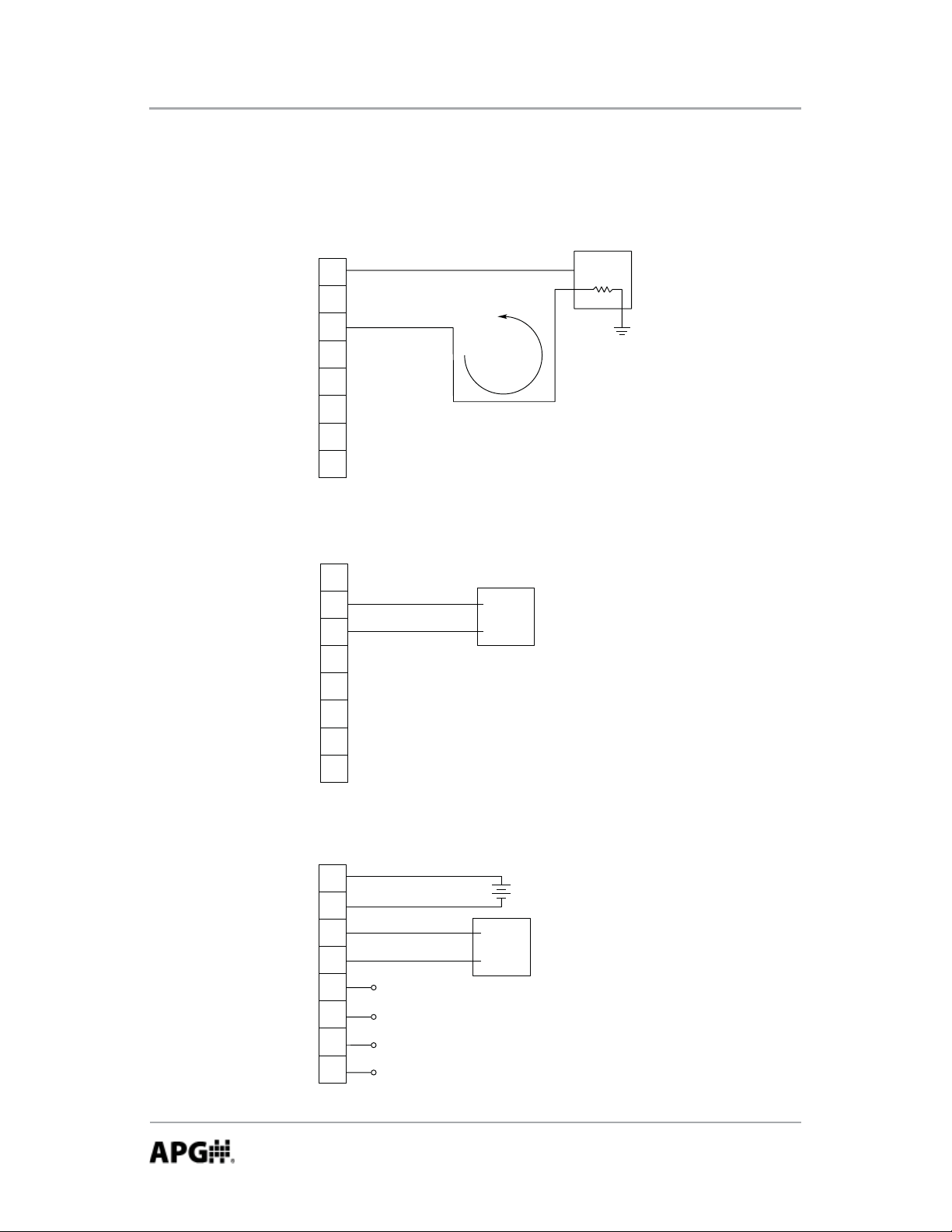
Wiring (continued)
L1: 4-20 mA Circuit
(C2 & C4 relay option not available)
Gauge
Connector
+ EXCITATION
1
2
– EXCITATION
3
4-20 mA
4
5
6
7
8
CURRENT
LOOP
L2: 0-2 V (battery powered)
(C2 & C4 relay options not available)
Gauge
Connector
1
2
3
Process
Controller
GROUND
+Vin
Process
Controller
+Vin
R
L
4
5
6
7
8
L3: 0-5 V
(SS relays on C2 option only)
Gauge
Connector
1
2
3
4
5
6
7
8
SS RELAY 1
SS RELAY 1
SS RELAY 2
SS RELAY 2
+
+Vin
GROUND
Process
Controller
SUPPLY
VOLTAGE
38
Automation Products Group, Inc.
APG...Providing tailored solutions for measurement applications
Tel: 1/888/525-7300 • Fax: 1/435/753-7490 • www.apgsensors.com • sales@apgsensors.com
Page 39

Rev. B, 6/11 PG10
Wiring (continued)
L4-C2: External Power with Dual SS Relays
Gauge
Connector
1
– EXCITATION
2
3
4
+
SUPPLY
VOLTAGE
5
6
7
8
SS RELAY 1
SS RELAY 2
L4-C4: External Power with Dual SPDT Relays
Gauge
Connector
1
– EXCITATION
2
3
4
5
6
7
8
Relay 1 Common
Relay 1 Normally Closed
Relay 1 Normally Open
Relay 2 Common
Relay 2 Normally Closed
Relay 2 Normally Open
L5: RS-485
(SS relays on C2 option only)
Gauge
Connector
1
– EXCITATION
2
3
4
5
6
7
8
RS-485 (A)
RS-485 (B)
Master Device
SS RELAY 1
SS RELAY 2
+
SUPPLY
VOLTAGE
+
SUPPLY
VOLTAGE
Automation Products Group, Inc.
APG...Providing tailored solutions for measurement applications
Tel: 1/888/525-7300 • Fax: 1/435/753-7490 • www.apgsensors.com • sales@apgsensors.com
39
Page 40

PG10 Rev. B, 6/11
Specifi cations:
Overpressure: 2x full scale
Burst Pressure: 4x full scale or 20,000 psig, whichever is less.
Accuracy (linearity & hysteresis): +/-0.25% or +/- 0.1% B.F.S.L.
Environmental:
Housing: IP65
0
Compensated Temp: 20 to 130
Storage Temp: -40 to 160
Operating Temp: 0 to 160
0
F (-40 to 710C)
0
F (-18 to 710C)
Electrical:
Batteries: (2) standard C cell
External Power: 9-28 VDC
F (-7 to 540C)
Physical:
Weight: 1.6 lb (0.73 kg)
Case Material: Injection molded Phenolic
40
Automation Products Group, Inc.
APG...Providing tailored solutions for measurement applications
Tel: 1/888/525-7300 • Fax: 1/435/753-7490 • www.apgsensors.com • sales@apgsensors.com
Page 41

Rev. B, 6/11 PG10
Output Specifi cations:
4-20 mA Output:
Input Voltage (Excitation): 9 VDC min (no load) to 28 VDC max
Input Current: 3-30 mA max
Signal Variance: +/-0.16 mA at set points
Output/Input: 2 wire loop powered
Resolution: 14 bit
Protection: Reversed polarity
0-2 VDC Output:
Input Voltage (excitation): Battery powered
Output: Zero set point is +/-0.15 V with a 2 VDC span +/-0.02 VDC
Output/Input: 2 wire
Resolution: 14 bit
0-5 VDC Output:
Input Voltage (Excitation): 9 to 28 VDC
Input Current: 6 mA max
Output: 0-5 VDC / +/-0.5 VDC at set points
Output/Input: Non-isolated 3 wire
Resolution: 14 bit
Protection: Reversed polarity
Solid State Relay Trip Points:
Maximum Switched Voltage: 120 V AC/DC
Maximum Switched Current: 120 mA
SPDT Relay Trip Points:
Maximum Switched Voltage: 125 VAC; 24 VDC
Maximum Switched Current: 1 A
Automation Products Group, Inc.
APG...Providing tailored solutions for measurement applications
Tel: 1/888/525-7300 • Fax: 1/435/753-7490 • www.apgsensors.com • sales@apgsensors.com
41
Page 42

AUT OMATION
PRODUCTS
GROUP, INC.
APG...Providing tailored solutions
for measurement applications
Automation Products Group, Inc.
Tel: 1/888/525-7300
1/435/753-7300
Fax: 1/435/753-7490
e-mail: sales@apgsensors.com
www.apgsensors.com
Automation Products Group, Inc.
1025 W. 1700 N.
Logan, UT 84321
To order additional copies of this manual, ask for APG part number PN9003470 Rev. B, 6/11
 Loading...