

Page 1

AUTOMATION
Operator’s Manual
P R O D U C T S
GROUP, INC.
MPX
Series
Magnetostrictive Level Sensors
Doc 9003761
Rev. B 4/13
Automation Products Group, Inc.
APG...Providing tailored solutions for measurement applications
Tel: 1/888/525-7300 • Fax: 1/435/753-7490 • www.apgsensors.com • E-mail: sales@apgsensors.com
Page 2

MPX Series Magnetostrictive Level Sensors Rev. B, 4/13
Table of Contents
Warranty ........................................................................................ 3
How does it work?
Installaon
Wiring
...................................................................................... 5
.......................................................................................... 6-8
.......................................................................... 4
HazardousLocaonWiring ......................................................... 8
Communicaons/Soware
........................................................ 9-15
ConguringtheSoware...................................................... 10-11
MulpleSensorCommunicaons ......................................... 12-13
UsingtheProgrammingWindow ......................................... 14-15
Modbus Register Lists ........................................................... 16-17
SensorProgramming ............................................................... 18-34
ApplicaonParameters ........................................................ 14-29
SignalProcessingandControl(advancedonly) .................... 30-31
4-20mASengs ....................................................................... 32
Web Alarms .......................................................................... 33-34
SavingandRecallingSensorSengs ......................................... 35
InspeconandMaintenance ........................................................ 36
Specicaons
Dimensions
................................................................................ 37
.............................................................................. 38-39
CercateofCompliance ........................................................ 40-43
Automation Products Group, Inc.
2
APG...Providing tailored solutions for measurement applications
Tel: 1/888/525-7300 • Fax: 1/435/753-7490 • www.apgsensors.com • sales@apgsensors.com
Page 3

Rev. B, 4/13 MPX Series Magnetostrictive Level Sensors
•Warranty and Warranty Restricons
APG warrants its products to be free from defects of material and
workmanship and will, without charge, replace or repair any equipment
found defecve upon inspecon at its factory, provided the equipment
has been returned, transportaon prepaid, within 24 months from date
of shipment from factory.
THE FOREGOING WARRANTY IS IN LIEU OF AND EXCLUDES ALL OTHER
WARRANTIES NOT EXPRESSLY SET FORTH HEREIN, WHETHER EXPRESSED
OR IMPLIED BY OPERATION OF LAW OR OTHERWISE INCLUDING BUT
NOT LIMITED TO ANY IMPLIED WARRANTIES OF MERCHANTABILITY OR
FITNESS FOR A PARTICULAR PURPOSE.
No representaon or warranty, express or implied, made by any sales
representave, distributor, or other agent or representave of APG
which is not specically set forth herein shall be binding upon APG.
APG shall not be liable for any incidental or consequenal damages,
losses or expenses directly or indirectly arising from the sale, handling,
improper applicaon or use of the goods or from any other cause
relang thereto and APG’s liability hereunder, in any case, is expressly
limited to the repair or replacement (at APG’s opon) of goods.
Warranty repairs are made specically at the factory. Any on site service
will be provided at the sole expense of the Purchaser at standard eld
service rates.
All associated equipment must be protected by properly rated
electronic/electrical protecon devices. APG shall not be liable for any
damage due to improper engineering or installaon by the purchaser
or third pares. Proper installaon, operaon and maintenance of the
product becomes the responsibility of the user upon receipt of the
product.
Returns and allowances must be authorized by APG in advance. APG
will assign a Return Material Authorizaon (RMA) number which must
appear on all related papers and the outside of the shipping carton. All
returns are subject to the nal review by APG. Returns are subject to
restocking charges as determined by APG’s “Credit Return Policy”.
Automation Products Group, Inc.
APG...Providing tailored solutions for measurement applications
Tel: 1/888/525-7300 • Fax: 1/435/753-7490 • www.apgsensors.com • sales@apgsensors.com
3
Page 4

MPX Series Magnetostrictive Level Sensors Rev. B, 4/13
• How does it work?
The MP series level sensors are based on magnetostricve technology.
Inside the stainless steel stem is a wire waveguide made of a metal that has
magnetostricve properes. Magnetostricve means that the atoms in
the metal realign in the presence of a magnec eld causing the metal to
temporarily deform or elongate very slightly. Inside the oat(s) are permanent
magnets. When a quick pulse of current is sent through the wire waveguide,
the magnec eld generated by the current pulse interacts with the magnec
eld of the oat(s) to realign the atoms in the waveguide. This results in a
rapid torsion that sends vibraons through the waveguide at near the speed
of sound. The sensor picks up the vibraon pulse, and through precisely
measuring the me elapsed between the current pulse and the torsion
vibraon, determines with precision the locaon of the oat. The MP has the
capability to simultaneously monitor two oats on a single stem, giving it the
ability to measure an oil/water interface level in addion to the total tank level.
Automation Products Group, Inc.
4
APG...Providing tailored solutions for measurement applications
Tel: 1/888/525-7300 • Fax: 1/435/753-7490 • www.apgsensors.com • sales@apgsensors.com
Page 5
Rev. B, 4/13 MPX Series Magnetostrictive Level Sensors
• Installaon
The MPX should be installed in an area, indoors or outdoors, which meets the
following condions:
• The ambient temperature does not exceed -40oC to 85oC (-40oF to
+185oF)
• Relave humidity up to 100%
• Polluon Degree 2
• Measurement Category II
• Altude 2000 meters or less.
• Locate the Probe away from strong magnec elds, such as those produced by motors, transformers, solenoid valves, etc.
• The medium is free from metallic substances and other foreign maer.
• No corrosive gases such as NH3, SO2, Cl2, etc.
• No excessive vibraon
• Ample space for maintenance and inspecon.
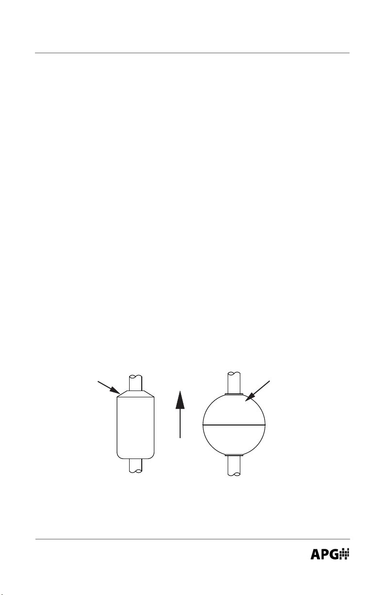
NOTE: Assure proper orientaon when installing the oat(s) on the stem
(refer to drawing below). Installing the oat(s) upsidedown can result in
unstable readings.
Taper Markings
XXXX
NC
UP
Automation Products Group, Inc.
APG...Providing tailored solutions for measurement applications
Tel: 1/888/525-7300 • Fax: 1/435/753-7490 • www.apgsensors.com • sales@apgsensors.com
5
Page 6
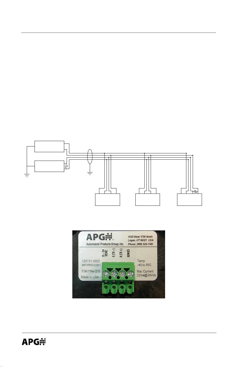
Modbus Daisy-Chain Wiring
MPX Series Magnetostrictive Level Sensors Rev. B, 4/13
• Sensor Wiring
All MPX models will operate on 10-24 Vdc. Always use a high quality power
source that will deliver clean, stable voltage.
Modbus RS-485 Wiring (MPX-E1 and MPX-R1 models)
Always use shielded cable. APG recommends using twisted-pair cable for all
Modbus network wiring.
+12-24 Vdc
Power
Supply
Master
Device
GND
RS-485 A
RS-485 B
120 Ω
terminating
resistor
Use Shielded Cable
B
V+
Sensor 1
120 Ω
terminating
resistor at last
A
GND
V+
Sensor 2
B
A
GND
B
V+
Sensor 3
sensor
A
GND
MPX-E1 and MPX-R1 wiring terminal
Automation Products Group, Inc.
6
APG...Providing tailored solutions for measurement applications
Tel: 1/888/525-7300 • Fax: 1/435/753-7490 • www.apgsensors.com • sales@apgsensors.com
Page 7
Rev. B, 4/13 MPX Series Magnetostrictive Level Sensors
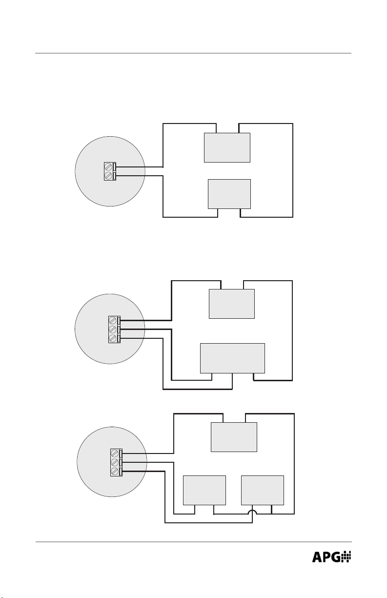
4-20 mA Loop Wiring (MPX-E2, MPX-R2 and MPX-E3, MPX-R3 models)
4-20 mA Loop Wiring
(MPX-E2 and MPX-R2 Series)
+
−
Sensor
12-24 Vdc
Out
Dual 4-20 mA Loop Wiring
(MPX-E3 and MPX-R3 Series)
Sensor
12-24 Vdc
Out 1
Out 2
Power Source
(12-24 Vdc)
Receiver
Input Com
−
+
Power Source
(12-24 Vdc)
Receiver
Input 1 Input 2 Com
OR
−
+
Sensor
12-24 Vdc
Out 1
Out 2
Automation Products Group, Inc.
APG...Providing tailored solutions for measurement applications
Tel: 1/888/525-7300 • Fax: 1/435/753-7490 • www.apgsensors.com • sales@apgsensors.com
Receiver 1
Input Com
Power Source
(12-24 Vdc)
Receiver 2
Input Com
7
Page 8
MPX Series Magnetostrictive Level Sensors Rev. B, 4/13
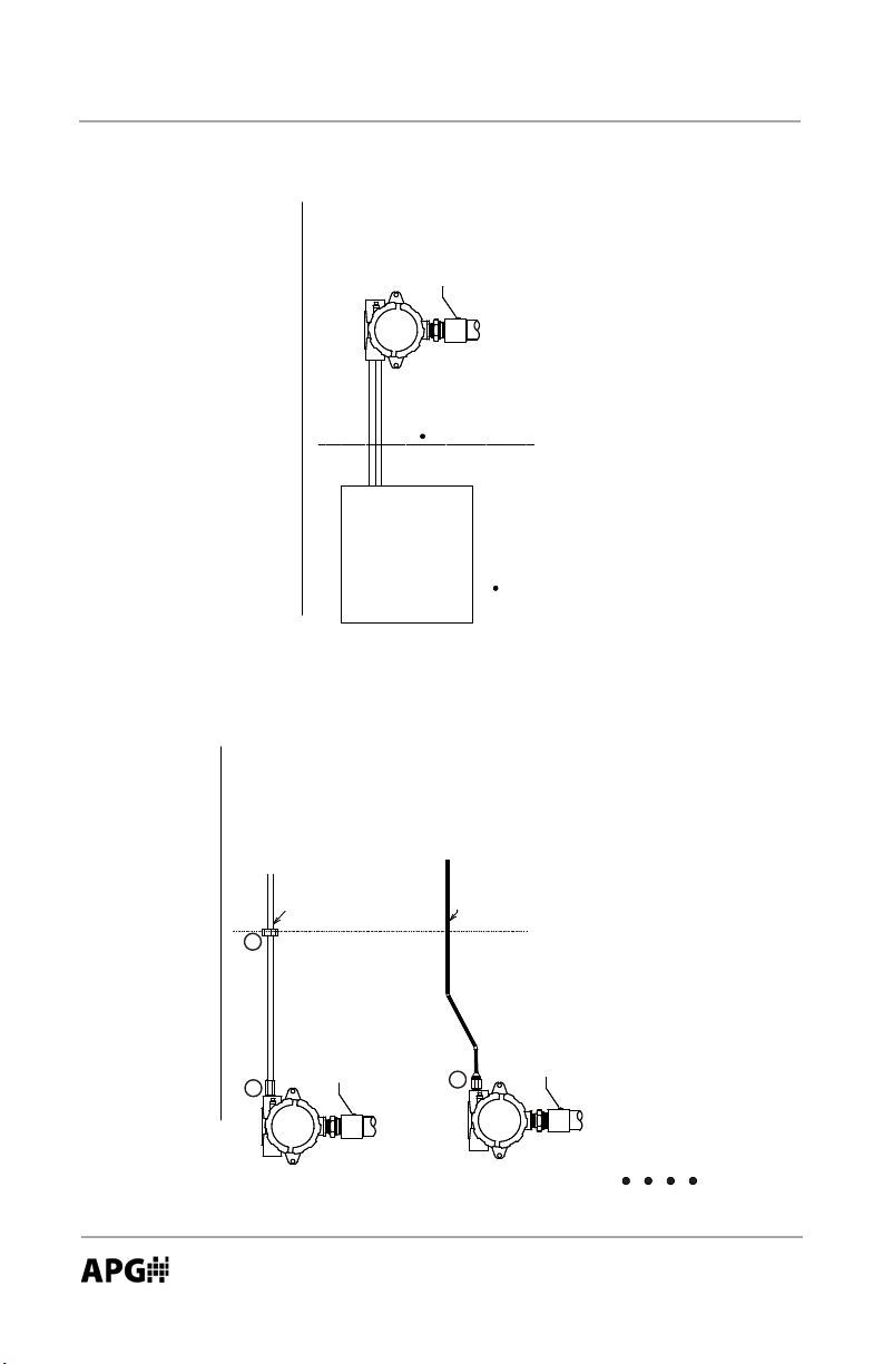
Hazardous Locaon Wiring
C
0
Earth Ground
Connection
Hazardous Area
Non-Hazardous Area
Non-Incendive Wiring for Installation in
Class I Division 2 Groups C and D, Max. Tep. 85
C
0
Non-Hazardous Area
CSA/UL Listed Conduit
Certied Associated
Vmax = 28VDC,
Imax = 200ma,
Non-Incendive
Field Wiring Apparatus
Ci = 0nF, Li = 0
CSA/UL Listed Hazardous Location Cable
Vmax ≥ Voc,
Ca ≥ Ccable + Ci
La ≥ Lcable + Li
B
Hazardous Area
Earth Ground
A
Connection
A
Earth Ground
Connection
Install in accordance with Section 18 of the CEC or Article 500 of the NEC.
CSA listed or NRTL/UL listed conduit seal at location A & B.
Do NOT disconnect while circuit is live unless area is known to be non-hazardous
Installation in: Class I Division 1 & 2 Groups C and D, Max. Temp. 85
Ex d IIB : Ex nA IIB
Class I, Zone 1; AEx d IIB : Class I, Zone 2; AEx nA IIB
Tapering or replacement with non-factory components may adversely aect the safe use of the system.
Automation Products Group, Inc.
APG...Providing tailored solutions for measurement applications
8
Tel: 1/888/525-7300 • Fax: 1/435/753-7490 • www.apgsensors.com • sales@apgsensors.com
Page 9
RST-4100
Rev. B, 4/13 MPX Series Magnetostrictive Level Sensors
• Sensor Communicaons
Modbus
(RS-485)
The MPX-E1 and MPX-R1 series ulizes standard Modbus RTU protocol (RS-
485). The sensor can only operate as a slave device. For more informaon
about Modbus RTU, please visit www.modbus.org.
The sensor will transmit at: 9600 baud, 8 bits, 1 Stop Bit, No parity (allow a
minimum delay of 300 ms between transacons).
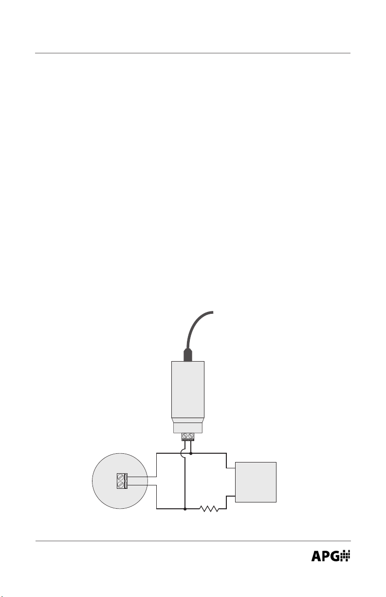
4-20 mA (requires RST-4100 module)
MPX-E2, MPX-R2, MPX-E3, and MPX-R3 sensor versions require the RST-4100
module and the APG Modbus soware for programming.
A load resistance is required at the DC Common (GND) end of the current
loop in order to establish communicaons. The RST-4100 is wired in parallel
between the power source and the sensor, with the load resistance between
the “Out” leg connecon and the power source ground (as shown below).
To USB
Programming Module
(MPX-E2, MPX-R2, MPX-E3, and MPX-R3)
Wiring
RST-4100
Out 24V
Note: a minimum of
14 Vdc is required to
Sensor
12-24 Vdc
Out
Load Resistor
(100 Ω to 700 Ω)
Automation Products Group, Inc.
APG...Providing tailored solutions for measurement applications
Tel: 1/888/525-7300 • Fax: 1/435/753-7490 • www.apgsensors.com • sales@apgsensors.com
establish communications
+
Power Source
(14- 24 Vdc)
−
9
Page 10
MPX Series Magnetostrictive Level Sensors Rev. B, 4/13
Conguring Soware Communicaons
All MPX versions use the same APG Modbus soware for sensor programming.
Use the following steps to congure the soware communicaons.
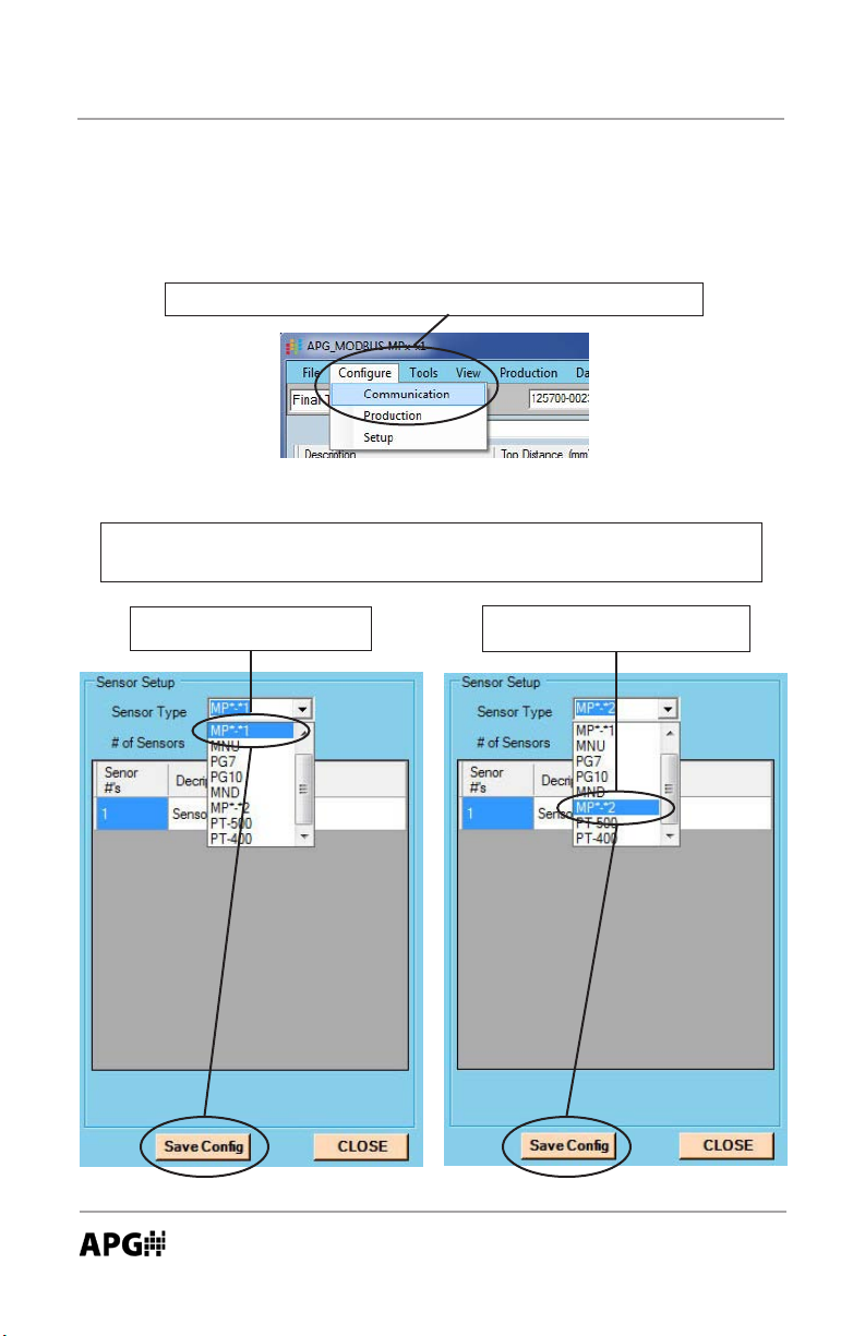
Step 1: select “Communicaon” from the “Congure” menu.
Step 2: select the appropriate Sensor Type, as shown below, then click the
“Save Cong” buon at the boom of the screen.
Modbus: select “MP*-*1”
(MPX-E1 and MPX-R1)
10
APG...Providing tailored solutions for measurement applications
Tel: 1/888/525-7300 • Fax: 1/435/753-7490 • www.apgsensors.com • sales@apgsensors.com
4-20 mA: select “MP*-*2”
(MPX-E2, MPX-R2, MPX-E3, MPX-R3)
Automation Products Group, Inc.
Page 11
Rev. B, 4/13 MPX Series Magnetostrictive Level Sensors
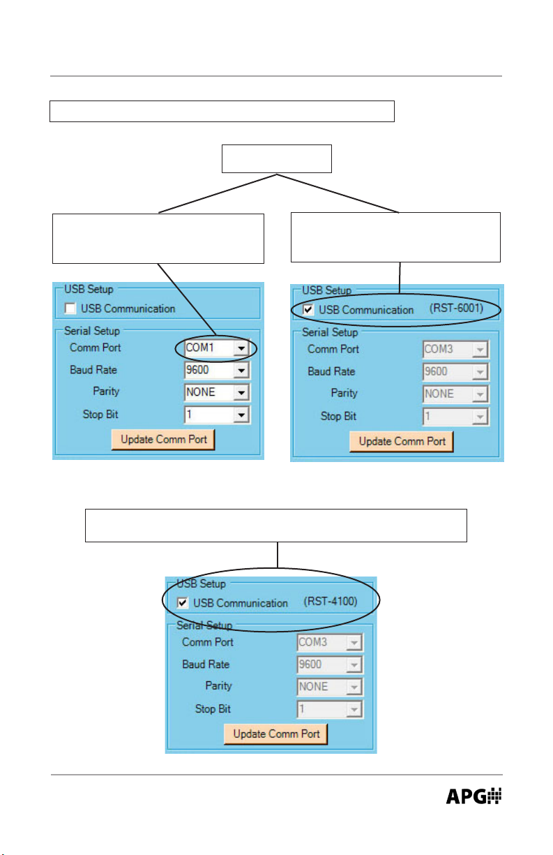
Step 3: select the mode of communicaon as shown below.
Modbus (RS-485):
(MPX-E1 and MPX-R1)
OR
Select the appropriate Comm Port
when using direct serial communica-
ons.
Check the “USB Communicaons
(RST-6001)” box when using the RST-
6001 communicaons module.
4-20 mA: check the box labeled “USB Communicaon (RST-4100)”
(MPX-E2, MPX-R2, MPX-E3, MPX-R3)
Automation Products Group, Inc.
APG...Providing tailored solutions for measurement applications
Tel: 1/888/525-7300 • Fax: 1/435/753-7490 • www.apgsensors.com • sales@apgsensors.com
11
Page 12
MPX Series Magnetostrictive Level Sensors Rev. B, 4/13
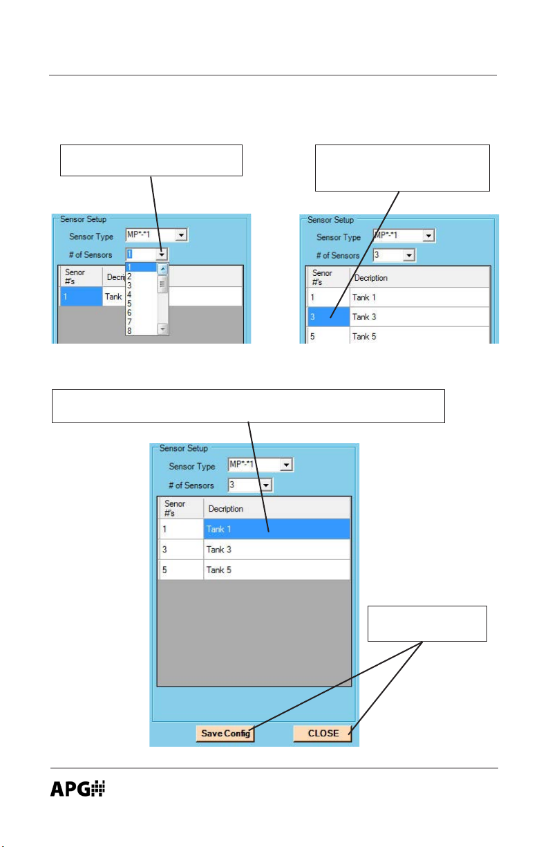
Conguring Soware Communicaons for Mulple Sensors
Step 1: select the total number
of sensors you wish to read.
Step 2: change the “Sensor #”
boxes to match the address’ of
the target sensors.
Step 3: Change the Descripon labels as desired. The Descripon is
used to dierenate between sensors in other areas of the soware.
12
Step 4: Click “Save
Cong” then “Close”.
(connued)
Automation Products Group, Inc.
APG...Providing tailored solutions for measurement applications
Tel: 1/888/525-7300 • Fax: 1/435/753-7490 • www.apgsensors.com • sales@apgsensors.com
Page 13
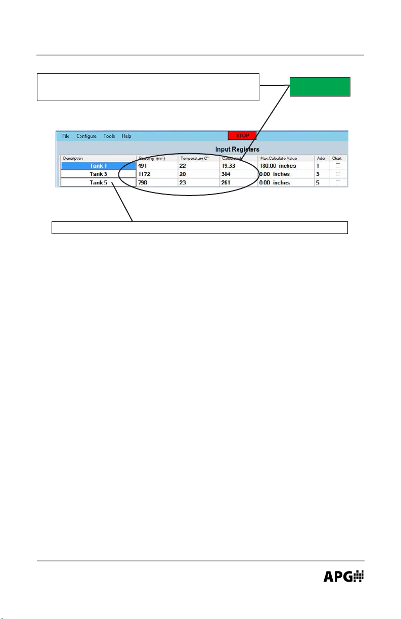
Rev. B, 4/13 MPX Series Magnetostrictive Level Sensors
Step 5: Click on “Start”. The sensor readings should
populate as the soware cycles through each sensor.
START
Step 6: Click on a sensor descripon to access that sensor’s parameters.
Automation Products Group, Inc.
APG...Providing tailored solutions for measurement applications
Tel: 1/888/525-7300 • Fax: 1/435/753-7490 • www.apgsensors.com • sales@apgsensors.com
13
Page 14
MPX Series Magnetostrictive Level Sensors Rev. B, 4/13
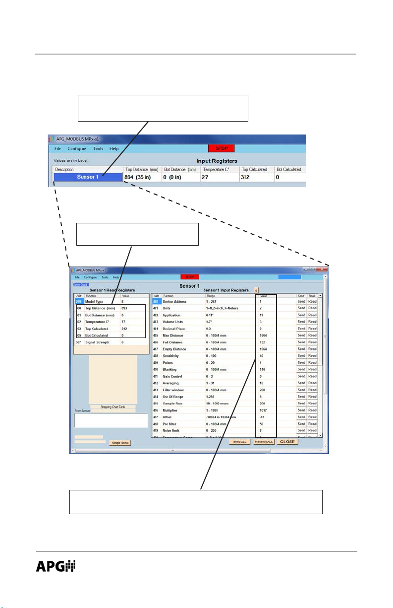
Using the Soware Programming Window
Click on the desired sensor descripon to
open that sensor’s programming window.
Sensor readings are displayed
in the Input Registers table.
14
The register values should automacally populate. If not, click
“Receive All” to retrieve the register values from the sensor.
(connued on next page)
Automation Products Group, Inc.
APG...Providing tailored solutions for measurement applications
Tel: 1/888/525-7300 • Fax: 1/435/753-7490 • www.apgsensors.com • sales@apgsensors.com
Page 15
Rev. B, 4/13 MPX Series Magnetostrictive Level Sensors
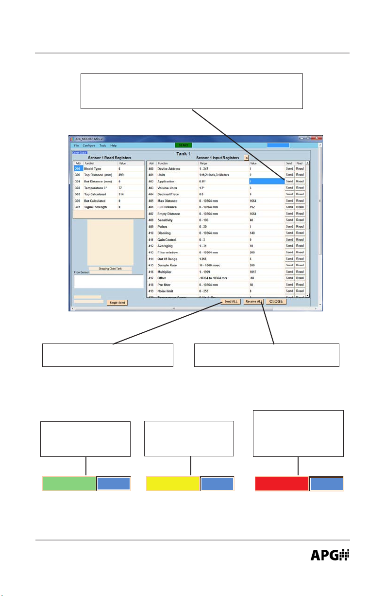
To change an individual parameter, click on the value
you wish to change, enter the desired value, then click
the adjacent “Send” buon to implement the change.
To send all the register values as
currently listed, click “Send All”
To retrieve the register values saved
in a sensor, click “Receive All”
A red window indi-
A green window
indicates successful
communicaon.
1500
APG...Providing tailored solutions for measurement applications
Tel: 1/888/525-7300 • Fax: 1/435/753-7490 • www.apgsensors.com • sales@apgsensors.com
Send
Automation Products Group, Inc.
A yellow window
indicates a communi-
caon failure.
1500
Send
cates a value outside
the allowable limits
for the parameter.
150000
Send
15
Page 16

MPX Series Magnetostrictive Level Sensors Rev. B, 4/13
Modbus Register Lists
Input Registers (0x04):
Register Returned Data
30300 Raw Top Float Reading (in mm, unsigned)
30301 Raw Boom Float Reading (in mm, unsigned)
30302 Temperature Reading (in 0C, signed)
30303-30304 Calculated Top Float Reading (in selected Units)
30305-30306 Calculated Boom Float Reading (in selected Units)
NOTE: the Calculated Readings will be returned without a decimal place. In
order to aain the true result, the Decimal Place seng must be taken into
account. Refer to the Decimal Place seng on page 19 for more informaon.
Holding Registers (0x03):
Register Funcon Value Range
40400 Device Address 1 to 255
40401 Units 1 to 3
40402 Applicaon Type 0-10
40403 Volume Units 0 to 6
40404 Decimal Place 0 to 10364 mm
40405 Max Distance 0 to 10364 mm
40406 Full Distance 0 to 10364 mm
40407 Empty Distance 0 to 10364 mm
40408 Sensivity 0 to 100
40409 Pulses 0 to 20
40410 Blanking 0 to 10364 mm
40411 Reserved n/a
40412 Averaging 0 to 100
40413 Filter Window 0 to 10364 mm
40414 Out of Range Samples 0 to 255
16
Automation Products Group, Inc.
APG...Providing tailored solutions for measurement applications
Tel: 1/888/525-7300 • Fax: 1/435/753-7490 • www.apgsensors.com • sales@apgsensors.com
Page 17

Rev. B, 4/13 MPX Series Magnetostrictive Level Sensors
(connued)
Register Funcon Value Range
40415 Sample Rate 50 to 1000 msec.
40416 Mulplier 1 to 1999
40417 Oset +/- 10364 mm
40418-40420 Reserved n/a
40421 RTD Oset (0C) -100 to 100
40422 Float Window 0 to 1000 mm
40423 Top Float Oset -10364 to 10364
40424 Boom Float Oset -10364 to 10364
40425 Gain Oset 0 to 255
40426 4 mA Set Point 0 to 10364 mm
40427 20 mA Set Point 0 to 10364 mm
40428 4 mA Calibraon 0 to 1000
40429 20 mA Calibraon 0 to 1000
40430 Web Alarm 1 Distance
40431 Web Alarm 1 Window
40432 Web Alarm 1 Type
40433 Web Alarm 2 Distance
40434 Web Alarm 2 Window
40435 Web Alarm 2 Type
40436-40437 Parameter 1 Data 0 to 100,000 mm
40438-40439 Parameter 2 Data 0 to 100,000 mm
40440-40441 Parameter 3 Data 0 to 100,000 mm
40442-40443 Parameter 4 Data 0 to 100,000 mm
40444-40445 Parameter 5 Data 0 to 100,000 mm
Automation Products Group, Inc.
APG...Providing tailored solutions for measurement applications
Tel: 1/888/525-7300 • Fax: 1/435/753-7490 • www.apgsensors.com • sales@apgsensors.com
17
Page 18

MPX Series Magnetostrictive Level Sensors Rev. B, 4/13
Applicaon Parameters
Device Address (1 to 255) (40400)
Each device within the Modbus network must be assigned a unique address.
Each MPX sensor should be connected to the network individually and assigned
an address. Each sensor is set to address 1 by default.
Units (1 = Feet, 2 = Inches, 3 = Meters) (40401)
Determines the units of measure for the calculated reading (Input registers
30303-30304 and 30305-30306) when in Applicaon Types 0, 1, 7, or 11 (Distance, Depth of level, Pounds, Curve Fit).
Applicaon Type (1 to 11) (40402)
Determines the type of calculated reading performed by the sensor (refer to
pages 10-18). The calculated readings can be queried from Input registers
30303-30304 (top oat) and 30305-30306 (boom oat).
Applicaon Type 0: Distance
Sets the zero reference at the top of the stem and measures downward to
the oat posion.
Register Funcon Value Range
40401 Units 1 to 3
40402 Applicaon Type 0
40404 Decimal Place 0 to 3
Applicaon Type 1: Depth of level
Sets the zero reference to the boom of the stem and measures upward to
the oat posion.
Register Funcon Value Range
40401 Units 1 to 3
40402 Applicaon Type 1
40404 Decimal Place 0 to 3
40406 Full Distance Typically = Blanking Distance
40407 Empty Distance 0 to 10364 mm
Automation Products Group, Inc.
18
APG...Providing tailored solutions for measurement applications
Tel: 1/888/525-7300 • Fax: 1/435/753-7490 • www.apgsensors.com • sales@apgsensors.com
Page 19

Rev. B, 4/13 MPX Series Magnetostrictive Level Sensors
Applicaon Type 2: Volume of cylindrical tank with/without hemispherical boom
Register Funcon Value Range
40402 Applicaon Type 2
40403 Volume Units 1 to 7
40404 Decimal Place 0 to 3
40406 Full Distance Typically = Blanking
40407 Empty Distance 0 to 10364 mm
40436-40437 Tank Diameter 0 to 100,000 mm
40438-40439 Boom Radius 0 to 100,000 mm
Diameter
Full
Distance
Empty
Distance
or
Boom
Radius
Automation Products Group, Inc.
APG...Providing tailored solutions for measurement applications
Tel: 1/888/525-7300 • Fax: 1/435/753-7490 • www.apgsensors.com • sales@apgsensors.com
19
Page 20
MPX Series Magnetostrictive Level Sensors Rev. B, 4/13
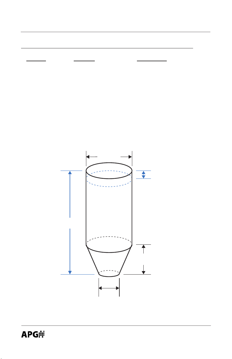
Applicaon Type 3: Volume of cylindrical tank with conical boom
Register Funcon Value Range
40402 Applicaon Type 3
40403 Volume Units 1 to 7
40404 Decimal Place 0 to 3
40406 Full Distance Typically = Blanking
40407 Empty Distance 0 to 10364 mm
40436-40437 Tank Diameter 0 to 100,000 mm
40438-40439 Cone Diameter 0 to 100,000 mm
40440-40441 Cone Length 0 to 100,000 mm
Diameter
Full
Distance
20
Empty
Distance
Cone
Length
Cone
Diameter
Automation Products Group, Inc.
APG...Providing tailored solutions for measurement applications
Tel: 1/888/525-7300 • Fax: 1/435/753-7490 • www.apgsensors.com • sales@apgsensors.com
Page 21
Rev. B, 4/13 MPX Series Magnetostrictive Level Sensors
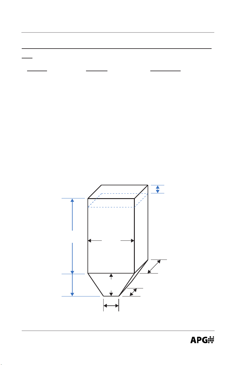
Applicaon Type 4: Volume of rectangular tank with/without chute bot-
tom
Register Funcon Value Range
40402 Applicaon Type 4
40403 Volume Units 1 to 7
40404 Decimal Place 0 to 3
40406 Full Distance Typically = Blanking
40407 Empty Distance 0 to 10364 mm
40436-40437 Tank X 0 to 100,000 mm
40438-40439 Tank Y 0 to 100,000 mm
40440-40441 Chute X 0 to 100,000 mm
40442-40443 Chute Y 0 to 100,000 mm
40444-40445 Chute Length 0 to 100,000 mm
Full
Distance
Empty
Distance
Tank X
Tank Y
or
Chute
Length
Chute Y
Chute X
Automation Products Group, Inc.
APG...Providing tailored solutions for measurement applications
Tel: 1/888/525-7300 • Fax: 1/435/753-7490 • www.apgsensors.com • sales@apgsensors.com
21
Page 22

Distance
MPX Series Magnetostrictive Level Sensors Rev. B, 4/13
Applicaon Type 5: Volume of horizontal cylindrical tank with or without
hemispherical ends
Register Funcon Value Range
40402 Applicaon Type 5
40403 Volume Units 1 to 7
40404 Decimal Place 0 to 3
40406 Full Distance Typically = Blanking
40407 Empty Distance 0 to 10364 mm
40436-40437 Tank Length 0 to 100,000 mm
40438-40439 Tank Diameter 0 to 100,000 mm
40440-40441 End Radius 0 to 100,000 mm
Full
Distance
22
Diameter
End
Radius
Length
Automation Products Group, Inc.
APG...Providing tailored solutions for measurement applications
Tel: 1/888/525-7300 • Fax: 1/435/753-7490 • www.apgsensors.com • sales@apgsensors.com
Empty
Page 23

Rev. B, 4/13 MPX Series Magnetostrictive Level Sensors
Applicaon Type 6: Volume of spherical tank
Register Funcon Value Range
40402 Applicaon Type 6
40403 Volume Units 1 to 7
40404 Decimal Place 0 to 3
40406 Full Distance Typically = Blanking
40407 Empty Distance 0 to 10364 mm
40436-40437 Tank Diameter 0 to 100,000 mm
Full
Distance
Empty
Distance
Automation Products Group, Inc.
APG...Providing tailored solutions for measurement applications
Tel: 1/888/525-7300 • Fax: 1/435/753-7490 • www.apgsensors.com • sales@apgsensors.com
Diameter
23
Page 24

MPX Series Magnetostrictive Level Sensors Rev. B, 4/13
Applicaon Type 7: Pounds
Allows the user to apply a conversion mulplier to the calculated level reading.
NOTE: the decimal point for the mulplier (40436-40437) is always assumed
to be in the thousands posion, therefore a seng of 206250 = 206.250
actual mulplier.
Example: suppose the product in a tank weighs 206.25 pounds for every inch
of level. With the Units set to inches (Units = 2), enter a mulplier of 206250
into Holding registers 40436-40437.
Register Funcon Value Range
40401 Units 1 to 3
40402 Applicaon Type 7
40404 Decimal Place 0 to 3
40406 Full Distance Typically = Blanking Distance
40407 Empty Distance 0 to 10364 mm
40436-40437 Mulplier 0 to 1000000 (1000 = 1.000)
Automation Products Group, Inc.
24
APG...Providing tailored solutions for measurement applications
Tel: 1/888/525-7300 • Fax: 1/435/753-7490 • www.apgsensors.com • sales@apgsensors.com
Page 25

Rev. B, 4/13 MPX Series Magnetostrictive Level Sensors
Applicaon Type 9: Volume of vercal oval tank
Register Funcon Value Range
40402 Applicaon Type 9
40403 Volume Units 1 to 7
40404 Decimal Place 0 to 3
40406 Full Distance Typically = Blanking
40407 Empty Distance 0 to 10364 mm
40436-40437 Tank Length 0 to 100,000 mm
40438-40439 Tank Depth 0 to 100,000 mm
40440-40441 Tank Width 0 to 100,000 mm
Full
Distance
Empty
Distance
Width
Depth
Length
Automation Products Group, Inc.
APG...Providing tailored solutions for measurement applications
Tel: 1/888/525-7300 • Fax: 1/435/753-7490 • www.apgsensors.com • sales@apgsensors.com
25
Page 26

MPX Series Magnetostrictive Level Sensors Rev. B, 4/13
Applicaon Type 10: Volume of horizontal oval tank
Register Funcon Value Range
40402 Applicaon Type 10
40403 Volume Units 1 to 7
40404 Decimal Place 0 to 3
40406 Full Distance Typically = Blanking
40407 Empty Distance 0 to 10364 mm
40436-40437 Tank Length 0 to 100,000 mm
40438-40439 Tank Depth 0 to 100,000 mm
40440-40441 Tank Width 0 to 100,000 mm
Full
Distance
26
Empty
Distance
Depth
Length
Width
Automation Products Group, Inc.
APG...Providing tailored solutions for measurement applications
Tel: 1/888/525-7300 • Fax: 1/435/753-7490 • www.apgsensors.com • sales@apgsensors.com
Page 27

Rev. B, 4/13 MPX Series Magnetostrictive Level Sensors
Applicaon Type 11: Curve Fit
Allows the sensor to mimic a tank strapping chart by using a 3rd degree polynomial equaon to produce a “curve t” approximaon.
Register Funcon Value Range
40401 Units 1 to 3
40402 Applicaon Type 11
40404 Decimal Place 0 to 3
40406 Full Distance Typically = Blanking
40407 Empty Distance 0 to 10364 mm
40436-40437 Parameter 1 0 to 100,000 mm
40438-40439 Parameter 2 0 to 100,000 mm
40440-40441 Parameter 3 0 to 100,000 mm
40442-40443 Parameter 4 0 to 100,000 mm
Open the APG Modbus soware and select “Strapping Chart” from the “Tools”
menu.
Enter the desired data points
into the table.
OR
Use the “Load” buon to recall a previously saved table.
OR
Import data from an electronic
document by copying the data
and then using the “Paste”
buon to populate the table.
Automation Products Group, Inc.
APG...Providing tailored solutions for measurement applications
Tel: 1/888/525-7300 • Fax: 1/435/753-7490 • www.apgsensors.com • sales@apgsensors.com
27
Page 28
MPX Series Magnetostrictive Level Sensors Rev. B, 4/13
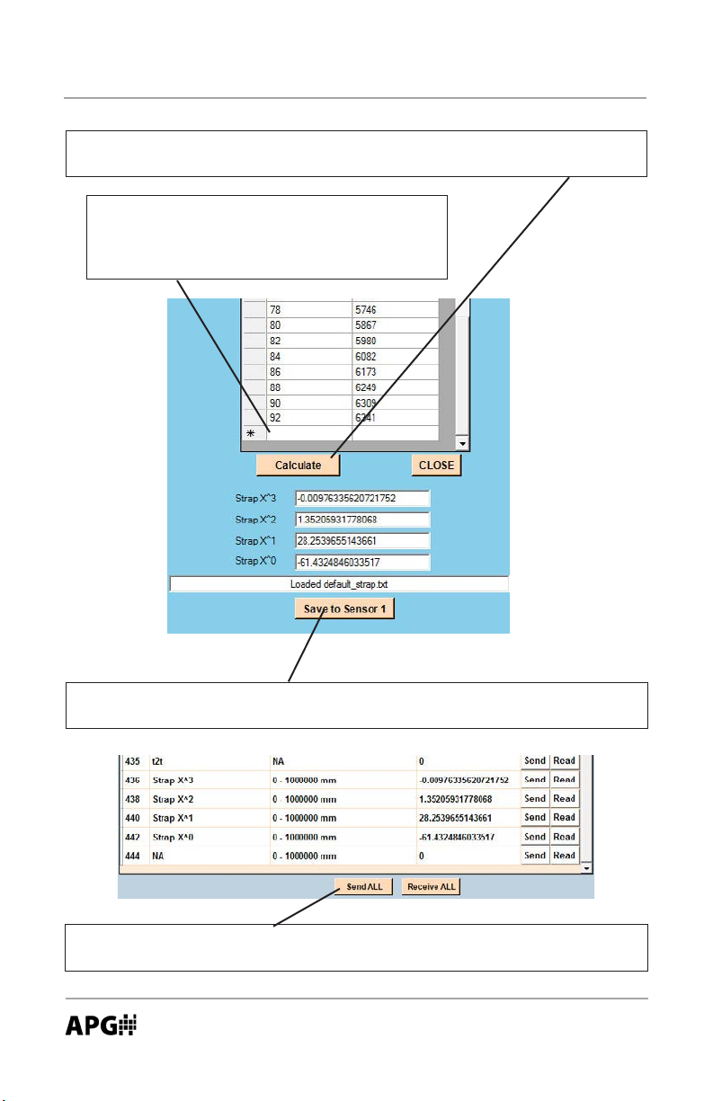
Once the all data points have been entered, click the “Calculate” buon to
determine the values required for the “curve t” calculaon.
NOTE: before clicking “Calculate” ensure that
there is only one empty row following the last
line of data (as shown). Use the keyboard
“Delete”key to remove any addion empty rows.
Click the “Save to Sensor” buon to populate the appropriate Holding Resister
elds (see below) and close the Strapping Chart window.
Click the “Send All” buon at the boom of the Holding Register page to write
the curve t values to the sensor.
Automation Products Group, Inc.
28
APG...Providing tailored solutions for measurement applications
Tel: 1/888/525-7300 • Fax: 1/435/753-7490 • www.apgsensors.com • sales@apgsensors.com
Page 29

Rev. B, 4/13 MPX Series Magnetostrictive Level Sensors
Volume Units (1 to 7) (40403)
Determine the units of measure for all volumetric Applicaon Types.
1 = Cubic Feet 4 = Cubic Meter 7 = Barrels
2 = Million Cubic Feet 5 = Liters
3 = Gallons 6 = Cubic Inches
Decimal Place (0 to 3) (40404)
Set the number of digits aer the decimal place to be included in the calculated
reading (Input registers 30303-30304 and 30305-30306)
Example: a measurement of 1126.658 will be returned as follows:
Decimal Place = 0 Volume = 1127
Decimal Place = 1 Volume = 11267
Decimal Place = 2 Volume = 112666
Decimal Place = 3 Volume = 1126658
*Maximum Distance (0 to 10364 mm) (40405)
Sets the distance, beginning from the zero reference, to where the sensor will
stop looking for a oat signal (usually the boom of the stem).
*Full Distance (0 to 10364 mm) (40406)
Sets the distance, beginning from the zero reference, to the point where the
tank is considered full (usually set to match the Blanking--see next page).
*Empty Distance (0 to 10364 mm) (40407)
Sets the distance, beginning from the zero reference, to the boom of the stem
OR the boom of the tank, whichever is considered the empty level.
Parameter Data (0 to 100,000 mm) (40436 to 40445)
The Parameter Data registers are used to enter tank dimensions or conversion
mulpliers for all the volumetric Applicaon Types (types 2-11). Refer to the
individual Applicaon Types for more informaon.
*refer to drawing on next page for more informaon
Automation Products Group, Inc.
APG...Providing tailored solutions for measurement applications
Tel: 1/888/525-7300 • Fax: 1/435/753-7490 • www.apgsensors.com • sales@apgsensors.com
29
Page 30

MPX Series Magnetostrictive Level Sensors Rev. B, 4/13
Full Distance
Increase the factory set Empty Distance
by “X” in millimeters (as shown below).
Empty
Distance
Maximum
Distance
Example for X = 25 mm (1”)
Factory sengs:
Maximum distance = 1500 mm (to end of stem)
Empty Distance = 1500 mm (to end of stem)
Adjusted Sengs:
Max Distance = 1500 mm
Empty Distance = 1525 mm
X (in mm)
30
Automation Products Group, Inc.
APG...Providing tailored solutions for measurement applications
Tel: 1/888/525-7300 • Fax: 1/435/753-7490 • www.apgsensors.com • sales@apgsensors.com
Page 31

Rev. B, 4/13 MPX Series Magnetostrictive Level Sensors
• Signal Processing and Control (advanced users only)
The parameters in this secon (pages 24-25) are advanced factory sengs and
should not normally need adjustment.
Sensivity (0 to 100%) (40408)
Controls the level of amplicaon applied to the oat signal. The sensivity setng is expressed as a percentage; 0 to 100%.
Pulses (0 to 20) (40409)
Controls the strength of the drive signal being sent down the magnetostricve
wire inside the stem. The greater the number of pulses, the stronger the drive
signal.
Blanking (0 to 10364 mm) (40410)
Sets the distance, beginning at the coil inside the upper stem, downward to the
point where the sensor will begin looking for the oat signal. If the oat enters
the blanking area it will not be detected. The blanking should never be set to
less than the top dead-band of the sensor.
Averaging (1 to 20) (40412)
Denes the number of oat readings that will be averaged together to become
the calculated reading. Each qualied oat reading (see Filter Window and
Out of Range Samples below) is placed into a rst-in, rst-out (FIFO) buer
and averaged with previous samples to generate a steady output. A higher
Averaging seng will result in smoother readings, but will also result in slower
response me to rapid level changes.
Filter Window (0 to 10364 mm) (40413)
Sets the width of the oat acceptance window. The oat acceptance window
is a zone, centered at the oat, within which any reading detected will be
considered legimate and gured into the averaging buer. Any reading
detected outside of the Window will be considered “out of range” and will
be ignored based on the seng in the Out of Range Samples parameter
(see below). The Filter Window extends both direcons from the oat. For
example, if the oat sits at 5 . and the Filter Window is set at 1 ., then any
reading detected between 4 . and 6 . will be accepted.
Automation Products Group, Inc.
APG...Providing tailored solutions for measurement applications
Tel: 1/888/525-7300 • Fax: 1/435/753-7490 • www.apgsensors.com • sales@apgsensors.com
31
Page 32

MPX Series Magnetostrictive Level Sensors Rev. B, 4/13
Out of Range Samples (1 to 255) (40414)
Determines the number of consecuve level readings that fall outside of the
acceptance window before the “out of range” target is recognized as being
legimate and gured into the averaging buer. Out of Range readings
detected fewer mes than the Out of Range Samples seng will be rejected.
Sample Rate (50 to 1000 msec) (40415)
Sets the interval between oat readings. Opons allow rates from 50 to
1000 msec. A higher Sample Rate will result in a more rapid response to level
changes. Lowering the Sample Rate will help decrease the chance of detecng
errant readings. It is highly recommended that the Sample Rate be set only as
fast as is necessary for the applicaon. A sample rate of 500 to 1000 msec. is
usually appropriate for slow moving level sensing applicaons.
Mulplier (0 to 19999) (40416)
Sets the calibraon mulplier that will be applied to the sensor readings.
Oset (-10364 to 10364 mm) (40417)
Used to adjust the zero reference point of the sensor.
RTD Oset (-100 to 100 mm) (40421)
Used to calibrate the internal temperature sensor located at the boom of the
stem (MPX-E1 and MPX-R1 only).
Float Window (0 to 1000 mm; 0 = single oat) (40422)
Sets the distance from top oat to the point where the sensor will start looking
for a second oat. If the Float Window is set too small, the trailing end of
the top oat signal will be picked up as the boom oat level, causing errant
readings.
NOTE: the Float Window should always be set to 0 when using only 1 oat.
1st and 2nd Float Oset (-10364 to 10364 mm) (40423 to 40424)
Used to calibrate the top and boom oat readings.
Gain Oset (0 to 255) (40425)
Factory set--do not adjust. Default = 128.
Automation Products Group, Inc.
32
APG...Providing tailored solutions for measurement applications
Tel: 1/888/525-7300 • Fax: 1/435/753-7490 • www.apgsensors.com • sales@apgsensors.com
Page 33

Rev. B, 4/13 MPX Series Magnetostrictive Level Sensors
• 4-20 mA Sengs
MPX-E2, MPX-R2 and MPX-E3, MPX-R3 models only.
*4 mA Set-point (0 to 10364) (40426)
Sets the measurement value associated with a 4 mA signal. The set-point is
based on raw measurement value of register 30300 (in millimeters), and not
the calculated value of register 30303.
*20 mA Set-point (0 to 10364) (40427)
Sets the measurement value associated with a 20 mA signal. The set-point is
based on raw measurement value of register 30300 (in millimeters), and not
the calculated value of register 30303.
*4 mA Calibraon (0 to 1000) (40428)
Factory set--do not adjust.
*20 mA Calibraon (0 to 1000) (40429)
Factory set--do not adjust.
20 mA
Set-Point
4 mA
Set-Point
OR
4 mA
Set-Point
20 mA
Set-Point
Automation Products Group, Inc.
APG...Providing tailored solutions for measurement applications
Tel: 1/888/525-7300 • Fax: 1/435/753-7490 • www.apgsensors.com • sales@apgsensors.com
33
Page 34

MPX Series Magnetostrictive Level Sensors Rev. B, 4/13
•Web Alarming (40430 to 40435)
When the MP is interfaced with an LOE or RST-5002 web-enabled master
device, the MP can be congured to generate website alarms via levelandow.
com. Refer to the LOE or RST-5002 user manual for more informaon about
website alarms and using levelandow.com.
Trip Alarm 1 (40430) or Alarm 2 (40433) Distance
Sets the level (in mm), beginning the boom of the stem, to the rst (lowest)
actuaon point (refer to next page for more informaon).
Trip Alarm 1 Window (40431 or 40434)
Sets the level (in mm), beginning from the Trip Distance locaon, to the secondary actuaon point (refer to next page for more informaon).
Trip Alarm 1 Type (40432 or 40435)
Determines the operaonal logic performed by the Trip Alarm (refer to next
page for more informaon).
Conguring Trip Alarm Types for Website Alarming:
(refer to Trip Types on next page)
Placing a “1” in front of any of the Trip Types designates an acve trip point as
an alarm condion. For example; Trip Type 3 would be designated as 13, and
would iniate a website alarm whenever the trip is acve (on).
Placing a “2” in front of any of the Trip Types designates an inacve trip point as
an alarm condion. For Example; Trip Type 3 would be designated as 23, and
would iniate a website alarm whenever the trip is inacve (o).
Automation Products Group, Inc.
34
APG...Providing tailored solutions for measurement applications
Tel: 1/888/525-7300 • Fax: 1/435/753-7490 • www.apgsensors.com • sales@apgsensors.com
Page 35

Trip Type Explanaons
Rev. B, 4/13 MPX Series Magnetostrictive Level Sensors
Trip Type 0
(near)
Trip Type 1
(exclusive)
Trip Type 2
(hysteresis near)
Trip Type 3
(far)
Trip Type 4
(inclusive)
Trip Type 5
(hysteresis far)
Type 6: n/a
Trip
Distance
ON OFF OFF
ON
ON
OFF
OFF
OFF
Trip
Window
OFF
ON
(Raising Level)
OFF
(Falling Level)
ON
ON
ON
(Falling Level)
OFF
(Raising Level)
ON
OFF
ON
OFF
ON
Type 7 (Loss of Echo): the relay will acvate if the sensor enters a loss of echo condion (no
targets detected).
Type 8 n/a
Type 9 (Rate of Change): allows the user to dene a maximum rate of change (distance over
me), which if exceeded will acvate an alarm. The Trip Distance parameter is used to dene the
me value, and the Trip Window parameter is used to dene the distance value.
Automation Products Group, Inc.
APG...Providing tailored solutions for measurement applications
Tel: 1/888/525-7300 • Fax: 1/435/753-7490 • www.apgsensors.com • sales@apgsensors.com
35
Page 36
MPX Series Magnetostrictive Level Sensors Rev. B, 4/13
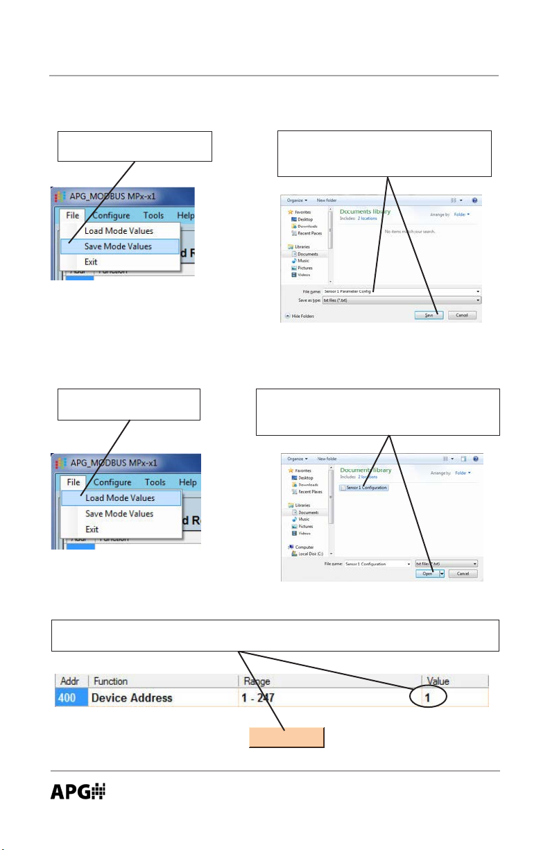
Saving Sensor Parameter Conguraons
Click on “File”, then select
“Save Mode Values”.
Choose a le name and the locaon
where you wish to save the le, then
click “Save”
Recalling Saved Sensor Conguraons
Click on “File”, then select “Load Mode Values”.
Choose a le you wish to upload, then
click “Open”. This will load the parameter
values into the soware.
Ensure the device address seng matches the target sensor’s address, then
click the “Send All” to write the parameters values to the sensor.
Send ALL
Automation Products Group, Inc.
36
APG...Providing tailored solutions for measurement applications
Tel: 1/888/525-7300 • Fax: 1/435/753-7490 • www.apgsensors.com • sales@apgsensors.com
Page 37

Rev. B, 4/13 MPX Series Magnetostrictive Level Sensors
• Inspecon and Maintenance
Periodically inspect the MPX unit to ensure that the stem is free of any heavy
buildup that might impede the movement of the oat. If sediment or other
foreign maer becomes trapped between the stem and the oat, detecon
errors can occur.
Ensure that the housing cover is snuggly secured. If the cover becomes
damaged or is misplaced, order a replacement immediately.
Automation Products Group, Inc.
APG...Providing tailored solutions for measurement applications
Tel: 1/888/525-7300 • Fax: 1/435/753-7490 • www.apgsensors.com • sales@apgsensors.com
37
Page 38

MPX Series Magnetostrictive Level Sensors Rev. B, 4/13
• Specicaons
Electrical Connecon: terminal block
Supply Voltage: 12 to 24 VDC
Current Draw
Modbus: 28 mA
4-20 mA: 22 mA (single), 44 mA (dual)
Output
MPX-x1: modbus (RS-485)
MPX-x2: 4-20 mA loop (2 wire)
MPX-x3: dual 4-20 mA loop (3 wire)
Resoluon
Modbus: 1 mm
4-20 mA: 14 bit
Accuracy: 0.05% of full scale reading
Top Dead-Band
MPX-E: 6 inches (150 mm)
MPX-R: 10 in (254 mm)
Temperature Sensor (modbus versions only): 1K RTD (+/- 1%)
Housing: cast aluminium, epoxy spray coated
Stem Material: 304 SS or 316L SS (MPX-R available in 316L SS only)
Environmental Protecon: NEMA 4X, IP65
Operang Temperature: -40 to 185 °F (-40 to 85°C)
Hazardous Locaon Approvals:
Class I Division 1 Groups C & D T4 (Ta 85°C)
Class I Division 2 Groups C & D T4 (Ta 85°C)
Class I, Zone 1; AEx d IIB T4
Class I, Zone 2; AEx nA IIB T4
Ex d IIB T4
Ex nA IIB T4
Specicaons are subject to change without noce.
For technical assistance, please contact APG at 435-753-7300.
Automation Products Group, Inc.
38
APG...Providing tailored solutions for measurement applications
Tel: 1/888/525-7300 • Fax: 1/435/753-7490 • www.apgsensors.com • sales@apgsensors.com
Page 39

Rev. B, 4/13 MPX Series Magnetostrictive Level Sensors
• MPX-R Dimensions
5.72”
4.30”
3/4” NPT
5.00”
10”
Dead-Band
(from reference)
6”
Dead-Band
(from reference)
7.00”
5.00”
5.50”
U & V
3.03”
W & X
Float Opons
Ref.
Ref.
2.80”
5.50”
Ø 0.25”
S & T
Ref.
3.07”
Y & Z
Ref.
5.10”
Automation Products Group, Inc.
APG...Providing tailored solutions for measurement applications
Tel: 1/888/525-7300 • Fax: 1/435/753-7490 • www.apgsensors.com • sales@apgsensors.com
3.08”
39
Page 40

MPX Series Magnetostrictive Level Sensors Rev. B, 4/13
• MPX-E Dimensions
5.72”
4.30”
3/4” NPT
5.00”
6”
Dead-Band
(from reference)
1.5”
Dead-Band
(from reference)
7.00”
2.00”
1.87”
A & B
2.06”
E
Float Opons
1.38”
Ref.
Ref.
2.20”
Ø 0.25”
C & D
Ref.
1.63”
F
Ref.
40
1.78”
1.47”
Automation Products Group, Inc.
APG...Providing tailored solutions for measurement applications
Tel: 1/888/525-7300 • Fax: 1/435/753-7490 • www.apgsensors.com • sales@apgsensors.com
Page 41

Model Number Configuraon
Rev. B, 4/13 MPX Series Magnetostrictive Level Sensors
MPX –
– – –
C D
E FA B
A Stem Type
E 0.5 in. diameter
R 1 in. diameter
B Output
1 Modbus RTU
2 4-20 mA (loop powered, 2-wire)
3 Dual 4-20mA (loop powered, 3-wire)
C Float 1
MPX-E (0.5 in. stem)
A 316L SS Round (0.65 SG)
B 316L SS Round (0.92 SG)
C 316L SS Cylindrical (0.61 SG)
D 316L SS Cylindrical(0.92 SG)
E Buna-N Cylindrical (0.65 SG)
F 316L SS Oval (0.5 SG)
MPX-R (1 in. stem)
S 316L SS Round 3 in. (0.94 SG)
T 316L SS Round 3 in. (0.58 SG)
U 316L SS Oval (94 SG)
V 316L SS Oval (0.63 SG)
W 316L SS Round (0.92 SG)
X 316L SS Round (0.52 SG)
Y Blue Polyurethane (0.94 SG)
Z Red Polyurethane (0.65 SG)
H
G
D Float 2 (oponal)
Refer to float opons in secons C
N None
E Mounng Opons (include size)
F FF Flange, 150# ANSI (size: 2, 2.5, 3, 4, 5, 6 in.)
R RF Flange, 150# ANSI (size: 2, 2.5, 3, 4, 5, 6 in.)
S Tri-Clamp (size: 2, 2.5, 3, 4 in.)
P NPT Plug (size: 1.5, 2, 2.5, 3, 4 in.)
N None
O Other
F Mounng Type
W Welded (fixed)
S Slide (adjustable)
G Stem Material
A 304 SS
B 316L SS*
*MPX-R is available in 316L SS only
H Total Stem Length (in inches)
MPX-E: min. 12 in. - max. 153 in.
MPX-R: min. 24 in. - max. 300 in.
Example: MPX-E1-AN-P2.5WB-60
A B C D E F
Accessories
Programming Modules Part Number
RST-6001 (Modbus models; MPX-x1) 125734
RST-4100 (4-20 mA models; MPX-x2, MPX-x3) 125759
Automation Products Group, Inc.
APG...Providing tailored solutions for measurement applications
Tel: 1/888/525-7300 • Fax: 1/435/753-7490 • www.apgsensors.com • sales@apgsensors.com
G
H
41
Page 42

MPX Series Magnetostrictive Level Sensors Rev. B, 4/13
Certificate of Compliance
Certificate:
Project:
Issued to: Automation Products Group Inc
2397437
2397437
1025 West 1700 North
Logan, UT 84321
USA
Attention: Karl Reid
The products listed below are eligible to bear the CSA
Mark shown with adjacent indicators 'C' and 'US' for
Canada and US or with adjacent indicator 'US' for
US only or without either indicator for Canada only.
Issued by:
Master Contract:
Date Issued:
Dennis Jerey
Dennis Jerey
237484
May 18, 2011
PRODUCTS
CLASS 2258 02
CLASS 2258 82
Class I, Division 1 & 2, Groups C, and D
Ex d IIB
Ex nA IIB
Class I, Zone 1; AEx d IIB
Class I, Zone 2; AEx nA IIB
Float Level Sensors, model MPX-ab-cd-efg-hhh, rated 12 - 24 Vdc, 80mA, or rated 12 to 24 Vdc, 4-20mA;
operating ambient Ta is 85°C; Temperature Code T4; Ingress protection IP65; Field wiring is non-incendive
when installed per drawing 9003468.
DQD 507 Rev. 2009-09-01 Page: 1
- PROCESS CONTROL EQUIPMENT - For Hazardous Locations
- PROCESS CONTROL EQUIPMENT - For Hazardous Locations Certied to US Standards
Automation Products Group, Inc.
APG...Providing tailored solutions for measurement applications
42
Tel: 1/888/525-7300 • Fax: 1/435/753-7490 • www.apgsensors.com • sales@apgsensors.com
Page 43

Rev. B, 4/13 MPX Series Magnetostrictive Level Sensors
Certificate:
Project:
Notes:
• The model code breakdown is as follows: a= E or R; b= 1, 2 or 3; c= A, B, C, D, E, F, Z, or Y; d= N, B, D, or
Y; e= F, R, P, N, or O; f= W or S; g= A or B; and hhh= 12–153 for the 1/2" stem or 48–300 for the 1" stem.
• The equipment is intended to be installed as required by the applicable electrical code (CEC, NEC) and as
specied by the manufacturers Installation Instructions.
• The installation will be inspected by the authority with jurisdiction in the area where installed.
APPLICABLE REQUIREMENTS
CSA C22.2 No 0-10 General Requirements – Canadian Electrical Code, Part
CSA C22.2 No 30-M1986 (R 2007) Explosion-Proof Enclosures for Use in Class I
CSA C22.2 No 142-M1987 (R 2009) Process Control Equipment Industrial Products – Third
CSA C22.2 No 213-M1987 (R 2008) Non-incendive Electrical Equipment for Use in Class I,
CSA C22.2 No 60079-0-07 Electrical apparatus for explosive gas atmospheres –
CSA C22.2 No 60079-1-07 Electrical apparatus for explosive gas atmospheres –
CSA E60079-15-02 (R 2006) Electrical Apparatus for Explosive Gas Atmospheres –
UL 508 Industrial Control Equipment - Seventeenth Edition;
UL 1203 Explosion-Proof and Dust-Ignition-Proof Electrical
ANSI/ISA-12.12.01-2007 Nonincendive Electrical Equipment for Use in Class
MARKINGS
The following markings are provided on a UL Recognized (PGJI2) adhesive nameplate manufactured by
Datamax, type FantaStock-HCW, printed with a resin ribbon manufactured by Datamax, type Greatribbon
SDR or SDR-5, which is suitable for indoor/outdoor use on polyurethane paint coatings, at a maximum service
temperature of 135°C or higher. Alternatively a screw or rivet secured metal nameplate or other permanent
2397437
2397437
II – Tenth Edition
Hazardous Locations Industrial Products – Third
Edition
Edition
Division 2 Hazardous Locations Industrial Products –
First Edition
Part 0: General requirements – First Edition
Part 1: Flameproof enclosures "d" – First Edition
Part 15: Type of Protection "n" – Second Edition
Reprint with Revisions Through and Including April
15, 2010
Equipment for Use in Hazardous (Classied) Locations
- Fourth Edition; Reprint with Revisions through and
Including October 28, 2009
I and II, Division 2 and Class III, Divisions 1 and 2
Hazardous (Classied) Locations
Master Contract:
Date Issued:
237484
May 18, 2011
DQD 507 Rev. 2009-09-01 Page: 2
Automation Products Group, Inc.
APG...Providing tailored solutions for measurement applications
Tel: 1/888/525-7300 • Fax: 1/435/753-7490 • www.apgsensors.com • sales@apgsensors.com
43
Page 44

MPX Series Magnetostrictive Level Sensors Rev. B, 4/13
Certificate:
Project:
manner can be used. The nameplate is axed to the top of the enclosure. Labels, if shown in the report, may
vary slightly in layout, provided that the required information continues to be shown.
The following markings appear on each product where applicable:
• Manufacturer’s name: "Automation Products Group", or CSA Master Contract Number “237484”, adjacent to
the CSA Mark in lieu of manufacturer’s name.
• Model number: As specied in the PRODUCTS section, above.
• Electrical ratings: As specied in the PRODUCTS section, above.
• Ambient temperature rating: As specied in the PRODUCTS section, above.
• Manufacturing date in MMYY format, or serial number, traceable to month of manufacture.
• Enclosure ratings: As specied in the PRODUCTS section, above.
• The CSA Mark with or without “C” and “US” indicators, as shown on the Certicate of Conformity.
• Hazardous Location designation: As specied in the PRODUCTS section, above (may be abbreviated).
• Temperature code: As specied in the PRODUCTS section, above.
• The name or mark of the certicate issuer and the certicate reference in the following form: the last two
gures of the year of the certicate followed by the serial number of the certicate in that year.
• The following words:
• “OPEN CIRCUIT BEFORE REMOVING COVER” or "KEEP COVER TIGHT WHILE CIRCUITS ARE
• “WARNING – EXPLOSION HAZARD - Substitution of components may impair suitability for Class I,
• “WARNING – EXPLOSION HAZARD – Do not connect while circuit is live unless area is known to be
• “Install per drawing 9003468 (as appropriate for nonincendive eld wiring only).”
An installation manual or data sheet shall be supplied with each unit, containing the following minimum
marking information:
General: Technical specications, instructions for use and details of where technical assistance may be obtained
if required.
Equipment Ratings: This includes equipment supply, description of I/O connections, duty cycle and operating
environmental conditions.
• Pollution degree 2;
• Measurement category II;
• Altitude 2000 m;
• Humidity 0 to 100%;
• Electrical supply DC,
• Indoor and outdoor use statement;
• Temperature - 40°C to 85°C;
Equipment Installation: This includes instructions for assembly and mounting, location requirements, details for
special services (cooling supply, etc.) as applicable.
2397437
2397437
ALIVE”.
Division 2.”
nonhazardous.”
Master Contract:
Date Issued:
237484
May 18, 2011
DQD 507 Rev. 2009-09-01 Page: 3
Automation Products Group, Inc.
APG...Providing tailored solutions for measurement applications
44
Tel: 1/888/525-7300 • Fax: 1/435/753-7490 • www.apgsensors.com • sales@apgsensors.com
Page 45

Rev. B, 4/13 MPX Series Magnetostrictive Level Sensors
Certificate:
Project:
PERMANENTLY CONNECTED EQUIPMENT requires the special considerations to satisfy the CEC and the
Canadian deviations in the standard, including overcurrent and fault protection as required.
Equipment Operation: This includes explanations of operating controls and warning symbols used, and
instructions for interconnection, replacement of consumables (e.g. paper) and cleaning as required.
Equipment Maintenance: This includes instructions for preventative maintenance, inspection and cleaning,
replacement of parts, etc.
Note - Jurisdictions in Canada may require these markings to also be provided in French language. It is the
responsibility of the manufacturer to provide bilingual marking, where applicable, in accordance with the
requirements of the Provincial Regulatory Authorities. It is the responsibility of the manufacturer to determine
this requirement and have bilingual wording added to the "Markings".
2397437
2397437
Master Contract:
Date Issued:
237484
May 18, 2011
DQD 507 Rev. 2009-09-01 Page: 4
Automation Products Group, Inc.
APG...Providing tailored solutions for measurement applications
Tel: 1/888/525-7300 • Fax: 1/435/753-7490 • www.apgsensors.com • sales@apgsensors.com
45
Page 46

MPX Magnetostrictive Level Sensors Rev. B, 4/13
Notes
46
Automation Products Group, Inc.
APG...Providing tailored solutions for measurement applications
Tel: 1/888/525-7300 • Fax: 1/435/753-7490 • www.apgsensors.com • sales@apgsensors.com
Page 47

Rev. B, 4/13 MPX Magnetostrictive Level Sensors
Notes
Automation Products Group, Inc.
APG...Providing tailored solutions for measurement applications
Tel: 1/888/525-7300 • Fax: 1/435/753-7490 • www.apgsensors.com • sales@apgsensors.com
47
Page 48

AUTOMATION
P R O D U C T S
GROUP, INC.
APG...Providing tailored solutions
for measurement applications
Automation Products Group, Inc.
Tel: 1/888/525-7300
1/435/753-7300
Fax: 1/435/753-7490
e-mail: sales@apgsensors.com
www.apgsensors.com
Automation Products Group, Inc.
1025 W. 1700 N.
Logan, UT 84321
 Loading...