

Page 1

APG
MPI Magnetostrictive Level Sensors
User Manual
For The MPI-E, MPI-E Chemical, and MPI-R
Intrinsically Safe
Doc #9005622
R
Part #200336
Rev A, 12/2019
Page 2

Table of Contents
Introduction ................................................................................................................ iii
Warranty and Warranty Restrictions .................................................................... iv
Chapter 1: Specications and Options.....................................................................1
Dimensions ....................................................................................................................................1-3
Specications ...................................................................................................................................4
Model Number Congurator .......................................................................................................5-7
System Wiring Diagrams and IS Use Case Diagrams .......................................................... 8-9
Chapter 2: Installation and Removal Procedures and Notes ............................ 10
Tools Needed ................................................................................................................................... 10
ATEX Stated Conditions of Use ................................................................................................... 10
Physical Installation Notes ......................................................................................................... 10
Physical Installation Instructions ..............................................................................................11
Electrical Installation ....................................................................................................................11
Removal Instructions ................................................................................................................... 12
Chapter 3: Programming ..........................................................................................13
Modbus Programming .................................................................................................................. 13
Modbus Programming with RST-6001 and APG Modbus Software .................................... 13
Modbus Register Lists For MPI-E/R .....................................................................................13-14
MPI-E/R Modbus Sensor Parameters ................................................................................... 15-19
MPI-E/R Modbus Application Type Parameters ............................................................... 20-24
Chapter 4: Maintenance ...........................................................................................25
General Care .................................................................................................................................... 25
Repair and Returns ........................................................................................................................25
Chapter 5: Hazardous Location Installation and Certication .........................26
Intrinsically Safe Installation Drawing for Hazardous Locations ......................................26
CSA Certicate of Compliance .............................................................................................. 27-29
IECEX Certicate of Conformity ........................................................................................... 30-32
EU Declaration of Conformity ..................................................................................................... 33
ii
Tel: 1/888/525-7300 • Fax: 1/435/753-7490 • www.apgsensors.com • sales@apgsensors.com
Page 3

Introduction
237484
Thank you for purchasing an MPI series magnetostrictive level sensor from APG. We appreciate your
business and your trust. Please take a few minutes to familiarize yourself with your MPI and this manual.
The MPI level sensor provides highly accurate and repeatable level readings in a wide variety of liquid level
measurement applications. It is certied intrinsically safe for installation in hazardous areas by CSA, ATEX,
and IECEx for Class I, Division 1 and Class I, Zones 0 environments. The MPI-R’s large, buoyant, and robust
oats allow it to be used in harsh applications where fouling or buildup might otherwise be of concern.
The smaller, lighter weight oats of the MPI-E allow it to be used in applications where space is limited.
The MPI-E Chemical has a chemical resistant coating, allowing for use in corrosive, acidic, and marine
environments.
Reading your label
Every APG instrument comes with a label that includes the instrument’s model number, part number,
and serial number. Please ensure that the part number on your label matches your order. The following
electrical ratings and approvals are also listed on the label. Please refer to the Certicate of Compliance at
the back of this manual for further details.
8-24 VDC, Imax = 280 mA
Class I, Division 1, Groups C, D, T4; IP65
Class I, Zone 0, Ex/AEX ia, IIB, T4, Ga
Ex ia IIB, T4 ,Ga
(Ta = -40°C to 85°C)
C
US
Intrinsically Safe Wiring Requirements:
U
ATEX Certicate Number: Sira 19ATEX2072X
II 1G
Ex ia IIB T4 Ga
Ta: -40°C to 85°C
U
IECEx SIR 19.0026X
Ex ia IIB T4 Ga
Ta: -40°C to 85°C
= 28 V, Ii = 280 mA, Pi = 0.850 W, L
i
= 28 VDC, Ii = 280 mA, Pi = 0.850 W , Li = 3.50 μH, Ci = 0.374 μF
i
= 3.50 μH, Ci = 0.374 μF
i
Tel: 1/888/525-7300 • Fax: 1/435/753-7490 • www.apgsensors.com • sales@apgsensors.com
iii
Page 4
IMPORTANT: MPI level sensor MUST be installed according to drawing 9005491
(Intrinsically Safe Installation Drawing for Hazardous Locations) on page 26 to meet listed
approvals. Faulty installation will invalidate all safety approvals and ratings.
DANGER: OPEN CIRCUIT BEFORE REMOVING COVER or KEEP COVER TIGHT WHILE CIRCUITS ARE ALIVE;
AVERTISSEMENT -- COUPER LE COURANT AVANT D’ENLEVER LE COUVERCLE, ou GARDER LE COUVERCLE
FERME TANT QUE LES CIRCUITS SONT SOUS TENSION.
DANGER: WARNING -- EXPLOSION HAZARD -- SUBSTITUTION OF COMPONENTS MAY IMPAIR SUITABILITY
FOR CLASS I, DIVISION 2;
AVERTISSEMENT -- RISQUE D’EXPLOSION -- LA SUBSTITIOND E COMPOSANTSP EUTR ENDRE CE MATERIEL
INACCEPTABLE POUR LES EMPLACEMENTS DE CLASSE I, DIVISION 2.
DANGER: WARNING -- EXPLOSION HAZARD -- DO NOT DISCONNECT EQUIPMENT UNLESS POWER HAS
BEEN SWITCHED OFF OR THE AREA IS KNOWN TO BE NON-HAZARDOUS;
AVERTISSEMENT -- RISQUE D’EXPLOSION -- AVANT DE DECONNECTER L’EQUIPEMENT, COUPER LE COURANT
OU S’ASSURER QUE L’EMPLACEMENT EST DESIGNE NON DANGEREUX.
Warranty and Warranty Restrictions
This product is covered by APG’s warranty to be free from defects in material and workmanship under
normal use and service of the product for 24 months. For a full explanation of our Warranty, please visit
https://www.apgsensors.com/about-us/terms-conditions. Contact Technical Support to receive a Return
Material Authorization before shipping your product back.
Scan the QR code below to read the full explanation of our Warranty on your tablet or smartphone.
iv
Tel: 1/888/525-7300 • Fax: 1/435/753-7490 • www.apgsensors.com • sales@apgsensors.com
Page 5
Chapter 1: Specications and Options
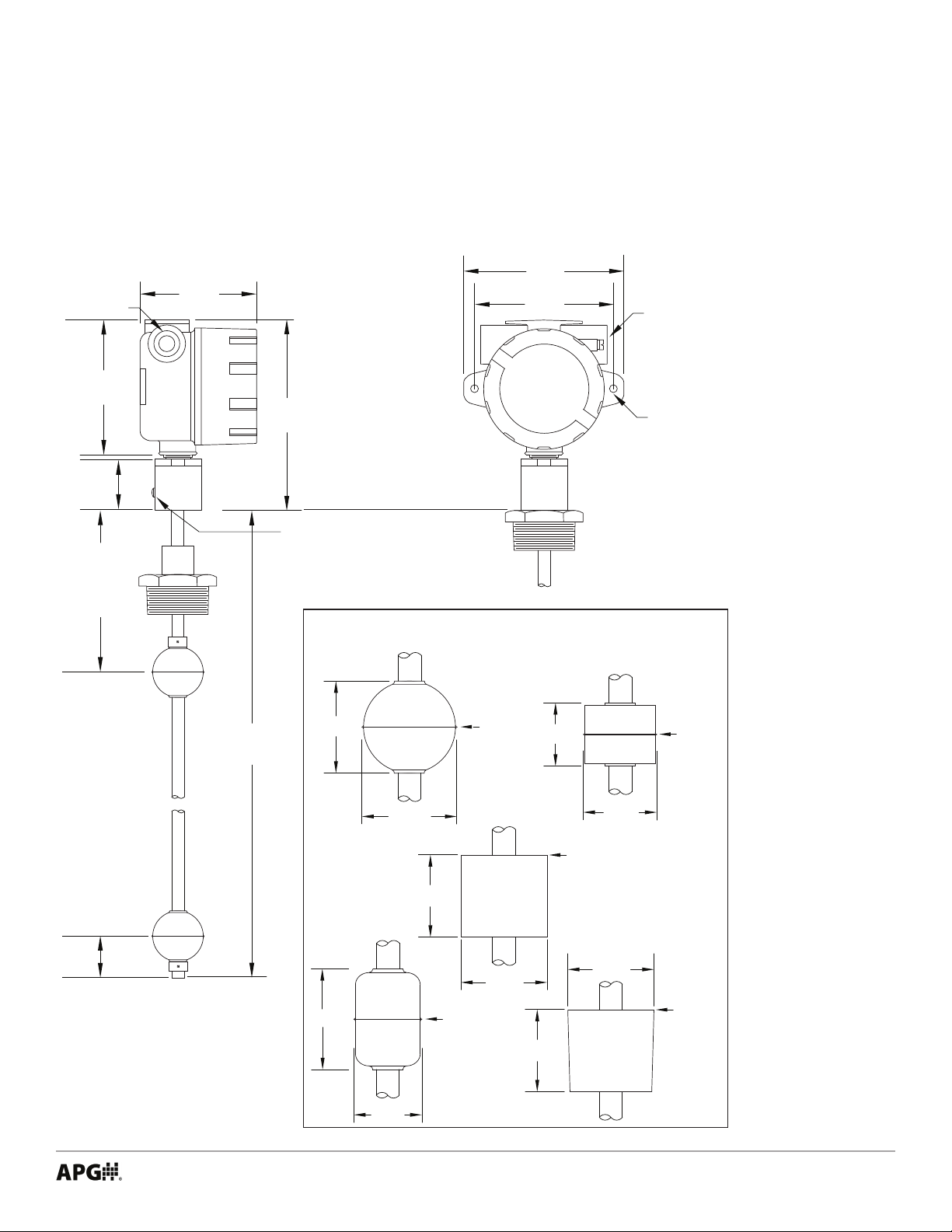
5.71”
• Dimensions
MPI-E Sensor and Float Dimensions
3/4” NPT
4.94”
4.15”
2.38”
S1
Dead-Band
(from Zero
Reference to
Float Ref.)
4.21”
3.74”
7.32-7.44”
6.53-6.65”
Min. 12”
Max. 153”
Note:
For dual dimensions, large
housing dimensions are
above small housing
dimensions.
ZERO
REFERENCE
GROUND
SCREW
A & B
2.00”
4.92”
5.00”
4.25”
Float Options
Float Ref.
S1=6”
S2=1.4”
1.38”
3/4” NPT
Housing
Connection
Location
Ø 0.27”
C & D
Float Ref.
S1=6”
S2=1.1”
S2
Dead-Band
(from Float
Ref. to bottom
of stem)
Float G Note:
S2 increases to 2.88” if
bottom float stop used.
2.06”
E
1.63”
Float Ref.
1.87”
F
S1=6”
S2=2.27”
G
1.78”
2.20”
Float Ref.
S1=6”
1.91”
S2=1.5”
1.47”
Tel: 1/888/525-7300 • Fax: 1/435/753-7490 • www.apgsensors.com • sales@apgsensors.com
1.88”
Float Ref.
S1=6”
S2=2.38”
1
Page 6
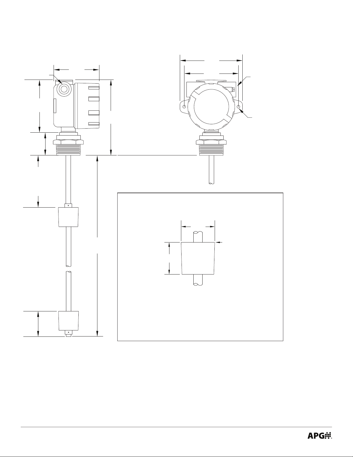
MPI-E Chemical Sensor and Float Dimensions
5.71”
3/4” NPT
4.94”
4.15”
2.13”
S1
Dead-Band
(from Zero
Reference to
Float Ref.)
4.21”
3.74”
Note:
For dual dimensions, large
housing dimensions are
above small housing
dimensions.
7.07”
6.28”
ZERO
REFERENCE
4.92”
5.00”
4.25”
Kynar Float
G
1.88”
3/4” NPT
Housing
Connection
Location
Ø 0.27”
S2
Dead-Band
(from Float
Ref. to bottom
of stem)
Min. 12”
Max. 153”
Float Ref.
1.91”
S1=6”
S2=2.38”
Note:
S2 increases to 2.88” if bottom float stop used.
2
Tel: 1/888/525-7300 • Fax: 1/435/753-7490 • www.apgsensors.com • sales@apgsensors.com
Page 7

MPI-R Sensor and Float Dimensions
5.71”
3/4” NPT
4.94”
1.90”
S1
Dead-Band
(from Zero
Reference to
Float Ref.)
4.21”
6.84” - 6.97”
ZERO
REFERENCE
GROUND
SCREW
I & J U & V
U & V / I & J
5.00”
3/4” NPT
Housing
Connection
Location
Ø 0.27”
Float Options
S & T
S2
Dead-Band
(from Float
Ref. to bottom
of stem)
Min. 48”
Max. 300”
5.00”
5.88”4.98”
3.03”
3.00”
W & X
Float Ref.
S1=10.63”
S2=6”
U & V
I & J
Float Ref.
S1=12.25”
S2=4.25”
2.80”
3.07”
Y & Z / L & M
5.50”
3.08”
Float Ref.
S1=12.25”
S2=4.25”
Float
Ref.
S1=10”
S2=6.5”
Y & Z
5.10”
Tel: 1/888/525-7300 • Fax: 1/435/753-7490 • www.apgsensors.com • sales@apgsensors.com
2.00”
L & M
3
Page 8

• Specications
Performance
Resolution 0.04 in. (1 mm)
Accuracy ±0.05% of Full Scale or 1 mm (whichever is larger)
Environmental
Operating Temperature -40° to 185° F (-40° to 85° C)
Enclosure Protection NEMA 4X, IP65
Maximum Operating Pressure MPI-E Chem: 30 PSIA @ 70° F (21° C)
Electrical
Supply Voltage 8-24 VDC on sensor
Typical Current Draw 24 mA (MPI-E)
25 mA (MPI-R)
Protection Reverse Polarity and Surge (per IEC 61000-4-5, 4-6, 4-7)
Materials of Construction
Housing Cast aluminum, epoxy coated
Stem MPI-E: 0.5” Ø 316L SS
MPI-E Chemical: 0.5” Ø 316L SS with chemical
resistant coating
MPI-R: 1” Ø 316L SS
Mounting (slide) 316L SS
Compression Fitting (slide) Aluminum with Neoprene bushing
Connectivity
Output Modbus RTU (RS-485)
Programming
RS-485 Optional RST-6001 USB-to-RS-485 converter
4
Tel: 1/888/525-7300 • Fax: 1/435/753-7490 • www.apgsensors.com • sales@apgsensors.com
Page 9

• Model Number Congurator
Model Number: MPI - _E_ __5__ _____ - _____ _____ - _____ _____ _____ __B__ - _____ - _____ - _____
A B C D E F G H I J K L
A. Stem Type
□ E 0.5 in. diameter 316L SS
B. Output
□ 5 Modbus RTU, with surge protection, Intrinsically Safe
C. Housing Type
All Housing Die-cast Aluminum, NEMA 4X, IP68, Blue
□ __ Large Housing
▲
□ A
Small Housing
□ B Large Housing with window
□ C Small Housing with window
D. Float 1 (Top Float)
□ A 316L SS Round (0.65 SG)
□ B 316L SS Round (0.92 SG)
□ C 316L SS Cylindrical (0.65 SG)
□ D 316L SS Cylindrical (0.92 SG)
□ E Buna-N (0.5 SG)
□ F 316 SS 3A Cylindrical (0.5 SG)
E. Float 2 (optional)
□ N None
□ B 316L SS Round (0.92 SG)†
□ D 316L SS Cylindrical (0.92 SG)††
F. Mounting Type
□ F Flat Face ANSI Flange 150#
(Sizes: 2, 2.5, 3, 4, 5, 6)
□ R Raised Face ANSI Flange 150#
(Sizes: 2, 2.5, 3, 4, 5, 6)
□ S Tri Clamp
(Sizes: 2, 2.5, 3)
□ P NPT Plug 150#
(Sizes: 2, 2.5, 3, 4)
□ N None
G. Mounting Size
□ __ See Mounting Type for available sizes
H. Mounting Connection
□ W Welded (xed)
□ S Slide with Compression Fitting (adjustable)
I. Stem Finish Material
□ B 316L SS
J. Total Stem Length in Inches
□ __ Min. 12 in. - Max. 153 in.
K. Temperature Sensor Options
▲
□ N
None
□ 1D Digital Temperature Sensor A, 12 in. from bottom of
probe
□ 2D Digital Temperature Sensors A, B
□ 3D Digital Temperature Sensors A, B, C
□ 4D Digital Temperature Sensors A, B, C, D
□ 5D Digital Temperature Sensors A, B, C, D, E
□ 6D Digital Temperature Sensors A, B, C, D, E, F
□ 7D Digital Temperature Sensors A, B, C, D, E, F, G
Note: Temperature sensors B - G are spaced evenly between
A and probe’s zero reference, with minimum of 2 in.
required between temperature sensors.
L. Housing Connection
▲
□ N
None
□ A 3/4” to 1/2” NPT Reducing Threads
□ B Cable Gland (Cable sold separately)
□ M 4-pin M12 Micro Connector Male
□ F 4-pin M12 Micro Connector Female
Note: ▲This option is standard.
Note: †Must be used with Top Float A.
Note: ††Must be used with Top Float C.
Tel: 1/888/525-7300 • Fax: 1/435/753-7490 • www.apgsensors.com • sales@apgsensors.com
5
Page 10

Model Number: MPI - _E_ __5__ _____ - __G__ __N__ - __P__ __2__ __W__ _____ - _____ - _____ - _____
A B C D E F G H I J K L
A. Stem Type
□ E 0.5 in. diameter 316L SS
B. Output
□ 5 Modbus RTU, with surge protection, Intrinsically Safe
C. Housing Type
All Housing Die-cast Aluminum, NEMA 4X, IP68, Blue
□ __ Large Housing
▲
□ A
Small Housing
□ B Large Housing with window
□ C Small Housing with window
D. Float 1
□ G Kynar Cylindrical (0.66 SG)
E. Float 2
□ N None
F. Mounting Type
□ P NPT Plug 150#
G. Mounting Size
□ 2 Size 2
Note: ▲This option is standard.
H. Mounting Connection
□ W Welded (xed)
I. Stem Finish Material
□ F Kynar Coating
□ G Abcite Coating
J. Total Stem Length in Inches
□ __ Min. 12 in. - Max. 153 in.
K. Temperature Sensor Options
▲
□ N
None
□ 1D Digital Temperature Sensor A, 12 in. from bottom of
probe
□ 2D Digital Temperature Sensors A, B
□ 3D Digital Temperature Sensors A, B, C
□ 4D Digital Temperature Sensors A, B, C, D
□ 5D Digital Temperature Sensors A, B, C, D, E
□ 6D Digital Temperature Sensors A, B, C, D, E, F
□ 7D Digital Temperature Sensors A, B, C, D, E, F, G
Note: Temperature sensors B - G are spaced evenly between
A and probe’s zero reference, with minimum of 2 in.
required between temperature sensors.
L. Housing Connection
▲
□ N
None
□ A 3/4” to 1/2” NPT Reducing Threads
□ B Cable Gland (Cable sold separately)
□ M 4-pin M12 Micro Connector Male
□ F 4-pin M12 Micro Connector Female
6
Tel: 1/888/525-7300 • Fax: 1/435/753-7490 • www.apgsensors.com • sales@apgsensors.com
Page 11

Model Number: MPI - _R_ __5__ _____ - _____ _____ - _____ _____ _____ __B__ - _____ - _____ - _____
A B C D E F G H I J K L
A. Stem Type
□ R 1 in. diameter 316L SS
B. Output
□ 5 Modbus RTU, with surge protection, Intrinsically Safe
C. Housing Type
All Housing Die-cast Aluminum, NEMA 4X, IP68, Blue
▲
□ __
Large Housing
□ B Large Housing with window
D. Float 1 (Top Float)
□ Z 5.5h x 3d in. Red Polyurethane (0.65 SG)
□ Y 5.5h x 3d in. Blue Polyurethane (0.94 SG)
□ X 5 in. Round 316L SS (0.52 SG)
□ W 5 in. Round 316L SS (0.92 SG)
□ V 6h x 3d in. Oval 316L SS (0.58 SG)
□ U 6h x 3d in. Oval 316L SS (0.94 SG)
□ T 3 in. Round 316L SS (0.60 SG)
□ S 3 in. Round 316L SS (0.94 SG)
□ M 5.5h x 2d in. Red Polyurethane (0.57 SG)
□ L 5.5h x 2d in. Blue Polyurethane (0.94 SG)
□ J 5h x 3d in. Oval Titanium 2 (0.60 SG)
□ I 5h x 3d in. Oval Titanium 2 (0.92 SG)
□ N None
E. Float 2 (optional)
□ N None
□ Y 5.5h x 3d in. Blue Polyurethane (0.94 SG)
□ W 5 in. Round 316L SS (0.92 SG)
□ U 6h x 3d in. Oval 316L SS (0.94 SG)
□ L 5.5h x 2d in. Blue Polyurethane (0.94 SG)
□ I 5h x 3d in. Oval Titanium 2 (0.92 SG)
F. Mounting Type
□ F Flat Face ANSI Flange 150#
(Sizes: 2, 2.5, 3, 4, 5, 6)
□ R Raised Face ANSI Flange 150#
(Sizes: 2, 2.5, 3, 4, 5, 6)
□ S Tri Clamp
(Sizes: 2, 2.5, 3)
□ P NPT Plug 150#
(Sizes: 2, 2.5, 3, 4)
□ N None
G. Mounting Size
□ __ See Mounting Type for available sizes
H. Mounting Connection
□ W Welded (xed)
□ S Slide with Compression Fitting (adjustable)
I. Stem Material
□ B 316L SS
J. Total Stem Length in Inches
□ __ Min. 48 in. - Max. 300 in.
K. Temperature Sensor Options
□ N None
▲
□ 1D
Digital Temperature Sensor A, 12 in. from bottom of
probe
□ 2D Digital Temperature Sensors A, B
□ 3D Digital Temperature Sensors A, B, C
□ 4D Digital Temperature Sensors A, B, C, D
□ 5D Digital Temperature Sensors A, B, C, D, E
□ 6D Digital Temperature Sensors A, B, C, D, E, F
□ 7D Digital Temperature Sensors A, B, C, D, E, F, G
Note: ▲This option is standard.
Note: Temperature sensors B - G are spaced evenly between
A and probe’s zero reference, with minimum of 2 in.
required between temperature sensors.
L. Housing Connection
▲
□ N
None
□ A 3/4” to 1/2” NPT Reducing Threads
□ B Cable Gland (Cable sold separately)
□ M 4-pin M12 Micro Connector Male
□ F 4-pin M12 Micro Connector Female
Tel: 1/888/525-7300 • Fax: 1/435/753-7490 • www.apgsensors.com • sales@apgsensors.com
7
Page 12
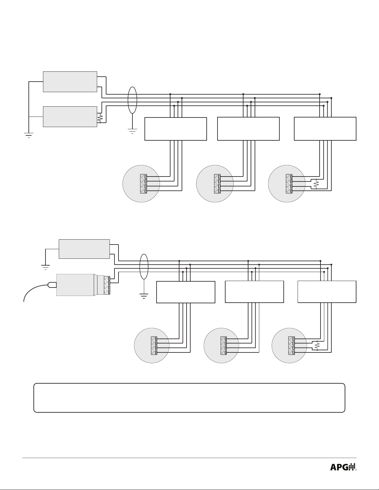
• System Wiring Diagrams and IS Use Case Diagrams
Modbus System Intrinsically Safe Wiring For MPI-E5, MPI-R5 Sensors
Power
Supply
Master
Device
120 Ω terminating resistor
may be necessary for long
+8-24 Vdc
GND
RS-485 A (TX+)
RS-485 B (TX-)
Use Shielded Cable
See Hazardous Installation
Drawing for Intrinsically Safe
installation requirements.
Otherwise, wire directly.
Wiring T’s must be located on
controller/supply side of IS barriers.
See Hazardous Installation
Drawing for Intrinsically Safe
installation requirements.
Otherwise, wire directly.
See Hazardous Installation
Drawing for Intrinsically Safe
installation requirements.
Otherwise, wire directly.
cable runs.
Note: When connecting MPI
sensors to your system, reversing
A and B connections may be necessary
if sensors do not communicate with
Modbus Master device.
MPI Sensor MPI Sensor MPI Sensor
Sensor 1
V+
B (TX-)
A (TX+)
GND
Sensor 2
V+
B (TX-)
A (TX+)
GND
Sensor 3
V+
B (TX-)
A (TX+)
GND
120 Ω terminating resistor across A & B
terminals of last or only sensor, if necessary.
For installations without IS barriers only.
Modbus System Intrinsically Safe Wiring with RST-6001 For MPI-E5, MPI-R5 Sensors
Power
Supply
+8-24 Vdc
GND
Use Shielded Cable
Wiring T’s must be located on
controller/supply side of IS barriers.
RST-6001
Modbus
Controller
USB to computer
with APG Modbus
software
Note: An independent +8-24 Vdc
power supply is required when using
an RST-6001 Modbus Controller. The
RST-6001 can only supply ±5 Vdc, not
the +8-24 Vdc required by the MPI.
IMPORTANT: Refer to Chapter 5 for Intrinsically Safe Installation Drawing for Hazard-
ous Locations.
A
B
-5V
+5V
Equivalent 120 Ω
terminating resistor
internal to RST-6001
See Hazardous Installation
Drawing for Intrinsically Safe
installation requirements.
Otherwise, wire directly.
MPI sensor
Sensor 1
V+
B
A
GND
See Hazardous Installation
Drawing for Intrinsically Safe
installation requirements.
Otherwise, wire directly.
MPI sensor MPI sensor
Sensor 2
V+
B
A
GND
120 Ω terminating resistor across A & B
terminals of last or only sensor, if necessary.
For installations without IS barriers only.
Sensor 3
V+
B
A
GND
See Hazardous Installation
Drawing for Intrinsically Safe
installation requirements.
Otherwise, wire directly.
8
Tel: 1/888/525-7300 • Fax: 1/435/753-7490 • www.apgsensors.com • sales@apgsensors.com
Page 13
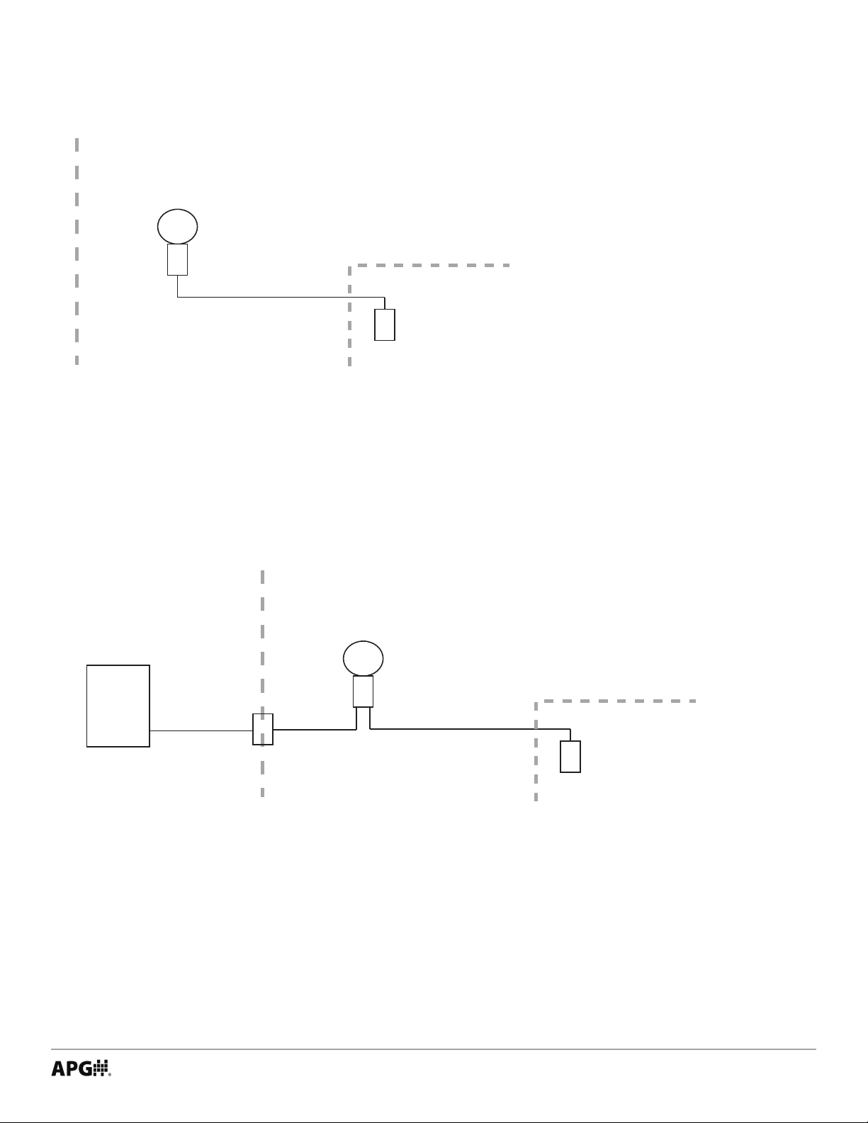
MPI - MDI Use Case Diagram
Hazardous Area
Zone 1
MDI
Modbus Address: Master
Controling: Sensor 1
Zone 0 or Zone 1
MPI Sensor
Modbus Address: 1
Single MDI controlling a single MPI sensor
• MDI is located in Zone 1 area. MPI can be in Zone 0 or Zone 1 without additional barriers.
• MDI is battery powered; allows for software-based switchable power for MPI.
• MPI is powered by MDI battery.
• No external controller.
• No IS barrier required.
• Any changes to MPI settings done via MDI buttons.
MPI - MDI with Passive Controller Use Case Diagram
Hazardous AreaNon-hazardous Area
Zone 1
MDI
Modbus Address: Master
Controling: Sensor 1
Zone 0 or Zone 1
Passive Control Equipment
Modbus: Sniffer
Approved
IS Barrier
Sniffing: MDI
Single MDI controlling a single MPI sensor with Passive Control Equipment
• MDI is located in Zone 1 area. MPI can be in Zone 0 or Zone 1 without additional barriers.
• MDI is battery powered; allows for software-based switchable power for sensor.
• MPI is powered by MDI battery.
• External controller passively reads (Snis) readings from MDI.
• External controller can activate MDI.
• Approved IS Barrier required between Passive Control Equipment and MDI.
• Auxiliary connection required for MDI.
• Any changes to MPI settings done via MDI buttons.
MPI Sensor
Modbus Address: 1
Tel: 1/888/525-7300 • Fax: 1/435/753-7490 • www.apgsensors.com • sales@apgsensors.com
9
Page 14

Chapter 2: Installation and Removal Procedures and Notes
• Tools Needed
You will need the following tools to install your MPI level sensor:
• Wrench sized appropriately for MPI mounting
• Wrench sized appropriately for conduit connections
• Flat-head screwdriver for wire terminals
• Channel lock pliers for tightening compression tting
• 3/32” hex Allen wrench for 1-piece MPI-E oat stops
• 1/8” hex Allen wrench for 1-piece MPI-R oat stops
• 3/16” hex Allen wrench for 2-piece MPI-R oat stops
• ATEX Stated Conditions of Use
• Under certain extreme circumstances, the non-metalic parts incorporated in the enclosure of this
equipment may generate an ignition-capable level of electrostatic charge. Therefore the equipment
shall not be installed in a location where the external conditions are conducive to the build-up of
electrostatic charge on such surfaces. In addition, the equipment shall only be cleaned with a damp
cloth.
• The enclosure is manufactured from Aluminum. In rare cases, ignition sources due to impact and
friction sparks could occur. This shall be considered during installation.
• Physical Installation Notes
The MPI should be installed in an area--indoors or outdoors--which meets the following conditions:
• Ambient temperature between -40°C and 85°C (-40°F to +185°F)
• Relative humidity up to 100%
• Altitude up to 2000 meters (6560 feet)
• IEC-664-1 Conductive Pollution Degree 1 or 2
• IEC 61010-1 Measurement Category II
• No chemicals corrosive to stainless steel (such as NH3, SO2, Cl2 etc.)
• Ample space for maintenance and inspection
Additional care must be taken to ensure:
• The probe is located away from strong magnetic elds, such as those produced by motors, transformers, solenoid valves, etc.
• The medium is free from metallic substances and other foreign matter.
• The probe is not exposed to excessive vibration.
• The oat(s) t through the mounting hole. If the oat(s) does/do not t, it/they must be mounted on
the stem from inside the vessel being monitored.
• The oat(s) is/are oriented properly on the stem (See Figure 2.1). MPI-E oats will be installed by the
factory. MPI-R oats are typically installed by customer.
10
Tel: 1/888/525-7300 • Fax: 1/435/753-7490 • www.apgsensors.com • sales@apgsensors.com
Page 15

NOTE: For MPI-E Chemical sensors: Chemical resitant coating will scar and expose
stainless steel if scraped or abused. Use caution when handling. Always transport in packaging to protect probe and coating.
Taper
IMPORTANT: Floats must be oriented proper-
UP
Figure 2.1
ly on the stem, or sensor readings will be inac-
curate and unreliable. Untapered oats will have
a sticker indicating the top of the oat. Remove
sticker prior to use.
IMPORTANT: MPI level sensor MUST be installed according to drawing 9005491
(Intrinsically Safe Installation Drawing for Hazardous Locations) on page 26, to meet listed
approvals. Faulty installation will invalidate all safety approvals and ratings.
• Physical Installation Instructions
• If your sensor’s stem and oats t through the mounting hole, carefully lower the assembly into the
vessel, then secure the sensor to the vessel.
• If the oats do not t, mount them on the stem from inside the vessel being monitored. Then secure
the sensor to the vessel.
• For sensors with oat stops, refer to the assembly drawing included with the sensor for oat stop
installation locations.
• For MPI-E Chemical, ensure probe is concentric with tting so as not to scrape chemical resistant coating o against threads of tting.
• Electrical Installation
• Remove the housing cover of your MPI.
• Feed system wires into MPI through 3/4” NPT conduit openings. Fittings must be UL/CSA Listed for CSA
installation.
• Connect wires to MPI terminals. Use crimped ferrules on wires, if possible.
• Replace the housing cover.
See System Wiring Diagrams and IS Use Case Diagrams (pages 8-9) for Modbus wiring examples.
Tel: 1/888/525-7300 • Fax: 1/435/753-7490 • www.apgsensors.com • sales@apgsensors.com
11
Page 16

• Removal Instructions
Removing your MPI level sensor from service should be done with care.
• If the oats on your sensor t through the mounting hole, carefully lift the entire sensor assembly out
of and away from the vessel.
• If the oats on your sensor do not t through the mounting hole, they will need to be removed from
the stem before the sensor can be removed. Be sure to drain the vessel being monitored to allow access to the oats and stem for removal.
• Clean the stem and oats of any build up or debris and inspect for damage.
• Store your sensor in a dry place, at a temperature between -40° F and 180° F.
12
Tel: 1/888/525-7300 • Fax: 1/435/753-7490 • www.apgsensors.com • sales@apgsensors.com
Page 17

Chapter 3: Programming
• Modbus Programming
MPI-E/R series sensors use standard Modbus RTU protocol (RS-485). The sensors can only operate as slave
devices. Sensor default transmission settings are 9600 Baud, 8 Bits, 1 Stop Bit, No Parity, and require a
minimum delay of 300 ms between transactions. See MPI-E/R Modbus Register Lists on pages 13 and 14.
NOTE: For more information about Modbus RTU, please visit www.modbus.org.
• Modbus Programming with RST-6001 and APG Modbus Software
An APG RST-6001 Modbus Controller can be used in tandem with APG Modbus to program and control up
to 20 MPI-E/R series sensors. Through APG Modbus, you can monitor the raw readings from the sensor,
congure the data for distance, level, volume, or weight, and enter measurements for a strapping chart. See
MPI-E/R Modbus Register Lists on pages 13 and 14.
NOTE: For APG Modbus programming instructions, or to download APG Modbus soft-
ware, please visit www.apgsensors.com/suppport.
• Modbus Register Lists for MPI-E/R
Input Registers (0x04)
Register Returned Data
30299 Model Type
30300 Raw Top Float Reading (in mm, unsigned)
30301 Raw Bottom Float Reading (in mm, unsigned)
30302 Temperature Reading (in 0C, signed)
30303-30304 Calculated Top Float Reading (in selected Units)
30305-30306 Calculated Bottom Float Reading (in selected Units)
30307 Version
30308 API 18.2 TEMP (in 0C, signed)
NOTE: The Calculated Readings will be returned without a decimal place. In order to
obtain the true result, the Decimal Place setting must be taken into account.
Tel: 1/888/525-7300 • Fax: 1/435/753-7490 • www.apgsensors.com • sales@apgsensors.com
13
Page 18

Holding Registers (0x03)
Register Function Value Range
40400 Device Address 1 to 247
40401 Units 1, 2, 3
40402 Application Type 0, 1, 2, 3, 4, 5, 6, 7, 8, 9, 10, 11
40403 Volume Units 1, 2, 3, 4, 5, 6, 7
40404 Decimal Place 0, 1, 2, 3
40405 †Max Distance 0 to 32,768 mm
40406 Full Distance 0 to 32,768 mm
40407 Empty Distance 0 to 32,768 mm
40408 †Sensitivity 0 to 100
40409 †Pulses 5 to 20
40410 †Blanking 0 to 10,364 mm
40411 NA NA
40412 †Averaging 1 to 50
40413 †Filter Window 0 to 10,364 mm
40414 †Out of Range Samples 1 to 255
40415 †Sample Rate 50 to 1,000 msec.
40416 †Multiplier 1 to 1,999 (1000 = 1.000)
40417 †Oset -10,364 to 10,364 mm
40418 †Pre lter 0 to 10,364 mm
40419 †Noise limit 0 to 255
40420 Temperature Select 0 to 8
40421 RTD Oset (0C) NA*
40422 †Float Window 0 to 1,000 mm 0=1 oat
40423 †1st Float Oset -10,364 to 10,364
40424 †2nd Float Oset -10,364 to 10,364
40425 †Gain Oset 0 to 255
40426 4 mA Set Point NA*
40427 20 mA Set Point NA*
40428 4 mA Calibration NA*
40429 20 mA Calibration NA*
40430 t1d NA*
40431 t1w NA*
40432 t1t NA*
40433 t2d NA*
40434 t2w NA*
40435 t2t NA*
40436-40437 Parameter 1 Data 0 to 1,000,000 mm
40438-40439 Parameter 2 Data 0 to 1,000,000 mm
40440-40441 Parameter 3 Data 0 to 1,000,000 mm
40442-40443 Parameter 4 Data 0 to 1,000,000 mm
40444-40445 Parameter 5 Data 0 to 1,000,000 mm
40446 Baud Rate 0, 1, 2, 3, 4
40201 Restore to Factory Defaults 1
*These registers are not used by the MPI-E/R, even though they are labeled in the APG Modbus software.
†Setting is factory calibrated. Do not adjust.
14
Tel: 1/888/525-7300 • Fax: 1/435/753-7490 • www.apgsensors.com • sales@apgsensors.com
Page 19

• MPI-E/R Modbus Sensor Parameters
40401 - Units
Determines the units of measure for the calculated reading when Application Type is set to 0, 1, or 7.
1 = Feet 2 = Inches 3 = Meters
40402 - Application Type
Determines the type of calculated reading performed by the sensor.
0 = Distance
1 = Level
2 = Standing Cylindrical Tank with or without Hemispherical Bottom
3 = Standing Cylindrical Tank with or without Conical Bottom
4 = Standing Rectangular Tank with or without Chute Bottom
5 = Horizontal Cylindrical Tank with or without Spherical Ends
6 = Spherical Tank
7 = Pounds (Linear Scaling)
8 = N/A
9 = Vertical Oval Tank
10 = Horizontal Oval Tank
11 = Strapping Chart
See MPI-E/R Modbus Application Type Parameters pages 20-24.
40403 - Volume Units
Determines the units of measure for the calculated reading when Application Type is set to 2 - 6 or 9 -11.
1 = Feet3 5 = Liters
2 = Million Feet3 6 = Inches3
3 = Gallons 7 = Barrels
4 = Meters3
40404 - Decimal Place
Determines the number of decimal places included in the Calculated Reading(s). The Calculated Reading will
always be returned as a whole number.
For example, a Calculated Reading of 1126.658 (gallons, ft3, etc.) will be returned as follows:
Decimal Place = 0 Volume = 1127 (rounded to nearest whole number)
Decimal Place = 1 Volume = 11267 (divide by 10 to get true result)
Decimal Place = 2 Volume = 112666 (divide by 100 to get true result)
Decimal Place = 3 Volume = 1126658 (divide by 1000 to get true result)
Tel: 1/888/525-7300 • Fax: 1/435/753-7490 • www.apgsensors.com • sales@apgsensors.com
15
Page 20

40405 - Maximum Distance (Factory Calibrated)
Sets the distance (beginning from the Zero Reference) to the point where the sensor will stop looking for
oat signals, usually the bottom of the stem. A oat beyond the Maximum Distance value will not be detect-
ed.
40406 - Full Distance
Sets the positive distance (beginning from the sensor Zero Reference) to the point where the monitored
vessel is considered full.
40407 - Empty Distance
Sets the positive distance (beginning from the Zero Reference) to the point where the monitored vessel is
considered empty (usually the bottom of the stem).
40408 - Sensitivity (Factory Calibrated)
Sets the level of gain that is applied to the returning oat signal.
40409 - Pulses (Factory Calibrated)
Controls the duration of the signal being sent down the magnetostrictive wire.
40410 - Blanking (Factory Calibrated)
Sets the blanking distance, which is the zone from the Zero Reference of the sensor to the point from which
the rst signal will be valid. Signals from a oat in the blanking area will be ignored.
40412 - Averaging (Factory Calibrated)
Sets the number of qualied received oat signals to average for the raw reading. Qualied received signals
are placed in a rst-in, rst-out buer, the contents of which are averaged for the raw reading. The larger
the number of qualied received signals being averaged, the smoother the reading will be, and the slower
the reading will be to react to quickly changing targets.
16
Tel: 1/888/525-7300 • Fax: 1/435/753-7490 • www.apgsensors.com • sales@apgsensors.com
Page 21

Example:
of Distance
40413 - Filter Window (Factory Calibrated)
Determines the physical range (0 - 10,364 mm) of qualied received signals, based on the current raw
reading. Signals beyond the +/- Filter Window range of the current reading will not qualify unless the
average moves. Signals outside the extents of the Filter Window are written to the Out of Range samples
buer (Holding Register 40414). See Figure 3.1.
Window = 300 mm
Out of Range Samples = 10
All samples
Samples are rejected within
this area unless they persist
for 10 consecutive samples
Current value
Min. Reading Max. Reading
are accepted
within this area
150 mm 150mm
Figure 3.1
Samples are rejected within
this area unless they persist
for 10 consecutive samples
40414 - Out of Range Samples (Factory Calibrated)
Sets the number of consecutive samples outside the Filter Window (Holding Register 40413) necessary to
automatically adjust the current reading and move the Filter Window.
40415 - Sample Rate (Factory Calibrated)
Sets the update rate of the sensor (between 50 - 1000 ms). Shorter time delays allow for quicker sensor
response times to changing levels. Typical setting is 200 ms. Settings under 200 ms are not recommended.
40416 - Multiplier (Factory Calibrated)
Calibrates the distance reading span. The Multiplier is shown by the values 1 - 1999, but these values are
understood to represent 0.001 - 1.999. The default of 1000 (i.e. 1.000) is used for most applications.
Tel: 1/888/525-7300 • Fax: 1/435/753-7490 • www.apgsensors.com • sales@apgsensors.com
17
Page 22

40417 - Oset (Factory Calibrated)
Sets the Zero Reference of the sensor, the point from which the calculated distance is measured.
40418 - Pre lter
Denes the physical range (0 - 10,364 mm) of the start up (pre-lter) window. Four sample readings must be
found within the Pre lter window for the MPI sensor to successfully start up.
This register is used for factory diagnostics only.
40419 - Noise limit
Sets the limit for number of signals (0-255) outside the Pre lter range for the MPI at start up. If the Noise
Limit is reached before four readings register within the Pre lter window, the MPI will not start up.
This register is used for factory diagnostics only.
40420 - Temperature Select
Selects the temperature sensor reading to be displayed in Input Register 30302.
MPI-E/R sensors can accomodate up to seven digital temperature sensors in the stem.
0 = Average of sensors A - G
1 = Digital Temperature Sensor A 5 = Digital Temperature Sensor E
2 = Digital Temperature Sensor B 6 = Digital Temperature Sensor F
3 = Digital Temperature Sensor C 7 = Digital Temperature Sensor G
4 = Digital Temperature Sensor D 8 = N/A
18
Tel: 1/888/525-7300 • Fax: 1/435/753-7490 • www.apgsensors.com • sales@apgsensors.com
Page 23

40422 - Float Window (Factory Calibrated)
Sets the distance (0 - 1000 mm) between the rst (i.e. top) oat and the point at which the sensor will begin
looking for the second (bottom) oat. 0 indicates a single oat.
40423 - 1st Float Oset (Factory Calibrated)
Used to calibrate top oat reading (-10,364 - 10,364 mm).
40424 - 2nd Float Oset (Factory Calibrated)
Used to calibrate bottom oat reading (-10,364 - 10,364 mm).
40425 - Gain Oset (Factory Calibrated)
Used to move the centerline of the oat response signal to optimize signal strength (0 - 255).
40446 - Baud Rate
Selects the communication speed between the sensor and the Master Device. All devices on the network
must use the same Baud Rate.
APG Modbus Master and Slave devices default to 9600 Baud.
0 = 9600
1 = 19200
2 = 38400
3 = 57600
4 = 115200
40201 - Restore To Factory Defaults
Writing a 1 to this Holding Register will erase any settings changes and restore the factory default settings.
Tel: 1/888/525-7300 • Fax: 1/435/753-7490 • www.apgsensors.com • sales@apgsensors.com
19
Page 24

Bottom
Radius
• MPI-E/R Modbus Application Type Parameters
Application 0 - Distance
Register Function Value Range
40400 Device Address 1 to 247
40401 Units 1 = Feet, 2 = Inches, 3 = Meters
40402 Application Type 0
40403 Volume Units -40404 Decimal (Calculated) 0 - 3
Application 1 - Level
Register Function Value Range
40400 Device Address 1 to 247
40401 Units 1 = Feet, 2 = Inches, 3 = Meters
40402 Application Type 1
40403 Volume Units -40404 Decimal (Calculated) 0 - 3
40405 Max Distance (factory set)
40406 Full Distance 0 - 32,768 mm
40407 Empty Distance 0 - 32,768 mm
Application 2 - Volume of Standing Cylindrical Tank ± Hemispherical Bottom
Register Function Value Range
40400 Device Address 1 to 247
40401 Units --
40402 Application Type 2
40403 Volume Units 1 - 7
40404 Decimal (Calculated) 0 - 3
40405 Max Distance (factory set)
40406 Full Distance 0 - 32,768 mm
40407 Empty Distance 0 - 32,768 mm
40436-40437 Tank Diameter 0 - 1,000,000 (mm)
40438-40439 Radius of Bottom Hemisphere 0 - 1,000,000 (mm)
NOTE: For all applications other than Distance, Empty Distance is usually the same as
Full
Level
or
Max Distance.
Diameter
20
Tel: 1/888/525-7300 • Fax: 1/435/753-7490 • www.apgsensors.com • sales@apgsensors.com
Page 25

Application 3 - Volume of Standing Cylindrical Tank ± Conical Bottom
Register Function Value Range
40400 Device Address 1 to 247
40401 Units --
40402 Application Type 3
40403 Volume Units 1 - 7
40404 Decimal (Calculated) 0 - 3
40405 Max Distance (factory set)
40406 Full Distance 0 - 32,768 mm
40407 Empty Distance 0 - 32,768 mm
40436-40437 Tank Diameter 0 - 1,000,000 (mm)
40438-40439 Cone Diameter (at bottom of cone) 0 - 1,000,000 (mm)
40440-40441 Length (height) of Cone 0 - 1,000,000 (mm)
Application 4 - Volume of Standing Rectangular Tank ± Chute Bottom
Register Function Value Range
40400 Device Address 1 to 247
40401 Units --
40402 Application Type 4
40403 Volume Units 1 - 7
40404 Decimal (Calculated) 0 - 3
40405 Max Distance (factory set)
40406 Full Distance 0 - 32,768 mm
40407 Empty Distance 0 - 32,768 mm
Full
Level
Full
Level
Tank X
Diameter
Cone
Diameter
Cone
Length
Tank Y
40436-40437 Tank X Dimension 0 - 1,000,000 (mm)
40438-40439 Tank Y Dimension 0 - 1,000,000 (mm)
40440-40441 Chute X Dimension 0 - 1,000,000 (mm)
40442-40443 Chute Y Dimension 0 - 1,000,000 (mm)
40444-40445 Length (height) of Chute 0 - 1,000,000 (mm)
Tel: 1/888/525-7300 • Fax: 1/435/753-7490 • www.apgsensors.com • sales@apgsensors.com
or
Chute
Length
Chute X
Chute Y
21
Page 26

Application 5 - Volume of Horizontal Cylindrical Tank ± Hemispherical Ends
Register Function Value Range
40400 Device Address 1 to 247
40401 Units --
40402 Application Type 5
40403 Volume Units 1 - 7
40404 Decimal (Calculated) 0 - 3
40405 Max Distance (factory set)
40406 Full Distance 0 - 32,768 mm
40407 Empty Distance 0 - 32,768 mm
40436-40437 Tank Length 0 - 1,000,000 (mm)
40438-40439 Tank Diameter 0 - 1,000,000 (mm)
40440-40441 Radius of End Hemispheres 0 - 1,000,000 (mm)
Diameter
End
Radius
Length
Application 6 - Volume of Spherical Tank
Register Function Value Range
40400 Device Address 1 to 247
40401 Units --
40402 Application Type 6
40403 Volume Units 1 - 7
40404 Decimal (Calculated) 0 - 3
40405 Max Distance (factory set)
40406 Full Distance 0 - 32,768 mm
40407 Empty Distance 0 - 32,768 mm
40436-40437 Tank Diameter 0 - 1,000,000 (mm)
Full
Level
Full
Level
Diameter
22
Tel: 1/888/525-7300 • Fax: 1/435/753-7490 • www.apgsensors.com • sales@apgsensors.com
Page 27

Application 7 - Pounds (Linear Scaling)
Register Function Value Range
40400 Device Address 1 to 247
40401 Units 1 = Feet, 2 = Inches, 3 = Meters
40402 Application Type 7
40403 Volume Units -40404 Decimal (Calculated) 0 - 3
40405 Max Distance (factory set)
40406 Full Distance 0 - 32,768 mm
40407 Empty Distance 0 - 32,768 mm
40436-40437 Multiplier (linear scalar) 0 - 1,000,000 (1000 = 1.000)
Application 8 - N/A
Application 9 - Volume of Vertical Oval Tank
Register Function Value Range
40400 Device Address 1 to 247
40401 Units --
40402 Application Type 9
40403 Volume Units 1 - 7
40404 Decimal (Calculated) 0 - 3
40405 Max Distance (factory set)
40406 Full Distance 0 - 32,768 mm
40407 Empty Distance 0 - 32,768 mm
40436-40437 Tank Length 0 - 1,000,000 (mm)
40438-40439 Tank Depth 0 - 1,000,000 (mm)
40440-40441 Tank Width 0 - 1,000,000 (mm)
Full
Level
Tel: 1/888/525-7300 • Fax: 1/435/753-7490 • www.apgsensors.com • sales@apgsensors.com
Width
Depth
Length
23
Page 28
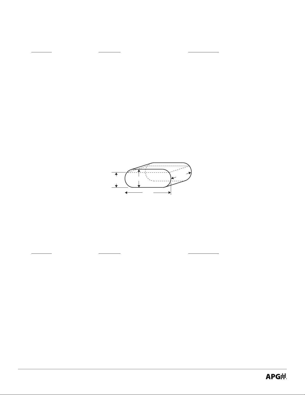
Application 10 - Volume of Horizontal Oval Tank
Register Function Value Range
40400 Device Address 1 to 247
40401 Units --
40402 Application Type 10
40403 Volume Units 1 - 7
40404 Decimal (Calculated) 0 - 3
40405 Max Distance (factory set)
40406 Full Distance 0 - 32,768 mm
40407 Empty Distance 0 - 32,768 mm
40436-40437 Tank Length 0 - 1,000,000 (mm)
40438-40439 Tank Depth 0 - 1,000,000 (mm)
40440-40441 Tank Width 0 - 1,000,000 (mm)
Full
Level
Depth
Width
Length
Application 11 - Strapping Chart (Polynomial Values)
Register Function Value Range
40400 Device Address 1 to 247
40401 Units 1 = Feet, 2 = Inches, 3 = Meters
40402 Application Type 11
40403 Volume Units 1 - 7
40404 Decimal (Calculated) 0 - 3
40405 Max Distance (factory set)
40406 Full Distance 0 - 32,768 mm
40407 Empty Distance 0 - 32,768 mm
40436-40437 X^3 Coecient 0 - 1,000,000
40438-40439 X^2 Coecient 0 - 1,000,000
40440-40441 X^1 Coecient 0 - 1,000,000
40442-40443 X^0 Coecient 0 - 1,000,000
24
Tel: 1/888/525-7300 • Fax: 1/435/753-7490 • www.apgsensors.com • sales@apgsensors.com
Page 29

Chapter 4: Maintenance
• General Care
Your MPI level sensor is designed to be low maintenance. However, in general, you should:
• Periodically inspect your MPI to ensure the stem and oats are free of any heavy buildup that might
impede the movement of the oats.
• Ensure the housing cover is snuggly secured. If the cover becomes damaged or is misplaced, order a
replacement immediately.
• Repair and Returns
The MPI-E Chemical’s chemical resistant coating is a durable thermoplastic. This means that if damage
occurs, repair is possible:
• Use a heat gun on a low setting to heat the damaged location until coating becomes soft and mallea-
ble. If coating begins to ripple or bubble, too much heat has been applied.
• With a blunt object, gently smear the coating to recover the damaged area.
• Allow chemical resistant coating patch to cool before reinstalling probe.
• Keep MPI-E Chemical probe and chemical resistant coating away from ammable material during
repair.
NOTE: If the damaged area is greater than 0.1”, it is recommended to use a supple-
mental patch of chemical resistant coating.
Should your MPI level sensor require service, please contact the factory via phone, email, or online chat. We
will issue you a Return Material Authorization (RMA) number with instructions.
• Phone: 888-525-7300
• Email: sales@apgsensors.com
• Online chat at www.apgsensors.com
Please have your part number and serial number available. See Warranty and Warranty Restrictions for
more information.
IMPORTANT: All repairs and adjustments of the MPI level sensor must be made by the
factory. Modifying, disassembling, or altering the MPI, other than patching the chemical
resistant coating on an MPI-E Chemical probe, is strictly prohibited.
Tel: 1/888/525-7300 • Fax: 1/435/753-7490 • www.apgsensors.com • sales@apgsensors.com
25
Page 30

Chapter 5: Hazardous Location Installation and Certication
• Intrinsically Safe Installation Drawing for Hazardous Locations
VERON TNEMUCODON TRAPEDOC EGAC
A
11
APPROVEDDATECHANGE ORDERDESCRIPTIONREVZONE
888.525.7300
Logan, Utah USA
1025 West 1700 North
MPI Series
9005491VARIOUS
SHEET OF
for Hazardous Locations
Intrinsically Safe Installation Drawing
CO-3441 retsedihC .C8102/92/8.esaeler laitinI-- A
Hazardous Location
REVISIONS
Class I, Division 1, Groups C,D T4
Unclassified Location
Class I, Zone 0, AEx ia IIB T4 Ga
Ex ia IIB T4 Ga, Ta -40°C to 85°C
MPI
Pi = 850mW
Li = 3.50uH
Vmax (or Ui) = 28V
Imax (or Ii) = 280mA
Ci = 0.374uF
6/5/2018
8/29/2018
8/29/2018
V+
RS-485 A
Associated Apparatus
with Entity Parameters
V- (GND)
RS-485 B
R. Barson
S. Hutchins
C. Chidester
APPROVALS DATE
- Installation must be in accordance with NEC Articles 504 and 505.
Po ≤ Pi
Ca (or Co) ≥ Ci + Ccable
Isc (or Io) ≤ Imax (or Ii)
La (or Lo) ≥ Li + Lcable
Voc (or Uo) ≤ Vmax (or Ui)
APVD
CHKD
DRWN
52797
A
SIZE
FINISH
MATL
CONTRACT
26
PROPRIETARY AND CONFIDENTIAL
Tel: 1/888/525-7300 • Fax: 1/435/753-7490 • www.apgsensors.com • sales@apgsensors.com
IF LOANED, IT IS SUBJECT TO RETURN
UPON DEMAND AND MAY NOT BE USED
DETRIMENTAL TO THE COMPANY.
IN ANY WAY DIRECTLY OR INDIRECTLY
LOGAN, UTAH AND MAY NOT BE
AUTOMATION PRODUCTS GROUP, INC.
DISCLOSED TO OTHERS WITHOUT
USED, REPRODUCED, PUBLISHED, OR
WRITTEN CONSENT OF THE COMPANY.
THIS DRAWING IS THE PROPERTY OF
Page 31

• CSA Certicate of Compliance
Certificate of Compliance
Certificate: 70219727 Master Contract: 237484
Project: 70219727 Date Issued: 2019-03-26
Issued to: Automation Products Group Inc
1025 West 1700 North
Logan, Utah 84321
USA
Attention: Karl Reid
The products listed below are eligible to bear the CSA Mark shown
with adjacent indicators 'C' and 'US' for Canada and US or with adjacent
indicator 'US' for US only or without either indicator for Canada only.
Issued by:
PRODUCTS
CLASS - C225804 - PROCESS CONTROL EQUIPMENT-Intrinsically Safe, Entity - For Hazardous
LocationsCLASS - C225884 - PROCESS CONTROL EQUIPMENT - Intrinsically Safe, Entity-- For Hazardous
Locations - Certified to US Standards
Class I, Division 1, Groups C, D, T4; IP 65*
Class I, Zone 0, Ex/AEx ia, IIB, T4, Ga
Ex ia IIB, T4, Ga
MPI Vibration Sensors, rated 8-24 VDC, Imax = 280 mA; Tamb = -40°C to +85°C, Intrinsically Safe when
installed per drawing 9005491
Entity Parameters: Ui= 28V, Ii= 280mA, Pi=0.850W, Li=
*IP 65 is only for STEM Type E, G, R, F and T.
The MPI series utilizes a configurator style model coding system as defined below:
MPI-ABC-DE-FGHI-J-K-LMNO-PQ
3.50H, Ci=0.374F
Jigneshkumar Dabhi
Jigneshkumar Dabhi
DQD 507 Rev. 2018-11-12 Page 1
Tel: 1/888/525-7300 • Fax: 1/435/753-7490 • www.apgsensors.com • sales@apgsensors.com
27
Page 32

Certificate:
Project:
1. Under certain extreme circumstances, the non-metallic parts incorporated in the enclosure
capable level of electrostatic charge.
2. T he enclosure is manufactured from Aluminum. In rare cases, ignition sources due to
Standard
Description
C22.2 No. 60079-0:2019
Explosive atmospheres – Part 0: Equipment – General
requirements
C22.2 No. 60079-11:2014
Explosive atmospheres — Part 11: Equipment protection by
intrinsic safety “i”
C22.2 No. 61010-1-12
Safety Requirements for electrical equipment for measurement,
control, and laboratory use – Part 1: General requirements
UL 61010-1:2012
UL Standard for Safety Electrical Equipment For Measurement,
Ed.
UL 60079-0: 2013
Standard for Safety – Explosive Atmospheres – Part 0: Equipment
– General Requirements, Ed. 6
70219727
70219727
Master Contract: 237484
Date Issued: 2019-03-26
Conditions of Acceptability:
of this equipment may generate an ignitionTherefore the equipment shall not be installed in a location where the external conditions
are conducive to the build-up of electrostatic charge on such surfaces. In addition, the
equipment shall only be cleaned with a damp cloth.
impact and friction sparks could occur. This shall be considered during installation.
3. IP 65 is not a part of the hazardous location ratings and is tested separately.
APPLICABLE REQUIREMENTS
Control, and Laboratory Use; Part 1: General Requirements, 3rd.
28
DQD 507 Rev. 2018-11-12 Page 2
Tel: 1/888/525-7300 • Fax: 1/435/753-7490 • www.apgsensors.com • sales@apgsensors.com
Page 33

Certificate:
Project:
UL 60079-11:2014
Standard for Safety – Explosive Atmospheres – Part 11:
Equipment Protection by Intrinsic Safety “I”, Ed. 6
70219727
70219727
Master Contract: 237484
Date Issued: 2019-03-26
MARKINGS
The manufacturer is required to apply the following markings:
Products shall be marked with the markings specified by the particular product standard.
Products certified for Canada shall have all Caution and Warning markings in both English and French.
Additional bilingual markings not covered by the product standard(s) may be required by the Authorities Having
Jurisdiction. It is the responsibility of the manufacturer to provide and apply these additional markings, where
applicable, in accordance with the requirements of those authorities.
The products listed are eligible to bear the CSA Mark shown with adjacent indicators 'C' and 'US' for Canada and
US (indicating that products have been manufactured to the requirements of both Canadian and U.S. Standards) or
with adjacent indicator 'US' for US only or without either indicator for Canada only.
1. Manufacturer’s name or registered trade mark;
2. Model Number as in the PRODUCTS section, above;
3. Serial number S/N XXXXXX;
4. “Install per document 9005491”
5. Ambient Temperature Rating: as specified in the PRODUCTS section above;
6. DC Power Symbol as per Table 1, IEC 61010-1:
7. Hazardous Location Designation: As specified in PRODUCTS section above;
8. IP 65 (Only for STEM Type Type E, G, R, F and T).
9. Certificate number: CSA19CA70219727
Nameplate adhesive label material approval information:
1. The following markings are provided on a UL Recognized adhesive nameplate (also used
previously on CSA certificate 2397437) manufactured by Zebra Technologies International, LLC,
Material: Z-Ultimate 4000T, printed with a resin ribbon manufactured by
Zebra Technologies
International LLC, Material: 5100 Premium Resin Ribbon, at a maximum service temperature of
135°C or higher.
DQD 507 Rev. 2018-11-12 Page 3
Tel: 1/888/525-7300 • Fax: 1/435/753-7490 • www.apgsensors.com • sales@apgsensors.com
29
Page 34

• IECEx Certicate of Conformity
30
Tel: 1/888/525-7300 • Fax: 1/435/753-7490 • www.apgsensors.com • sales@apgsensors.com
Page 35

Tel: 1/888/525-7300 • Fax: 1/435/753-7490 • www.apgsensors.com • sales@apgsensors.com
31
Page 36

32
Tel: 1/888/525-7300 • Fax: 1/435/753-7490 • www.apgsensors.com • sales@apgsensors.com
Page 37

• EU Declaration of Conformity
Tel: 1/888/525-7300 • Fax: 1/435/753-7490 • www.apgsensors.com • sales@apgsensors.com
33
Page 38

APG
R
Tel: 1/888/525-7300 • Fax: 1/435/753-7490 • www.apgsensors.com • sales@apgsensors.com
Automation Products Group, Inc.
 Loading...