

Page 1

Operator’s Manual
AUTOMATION
P R O D U C T S
GROUP, INC.
Automa! on Products Group, Inc.
APG...Providing tailored solu• ons for measurement applica• ons
Tel: 1/888/525-7300 • Fax: 1/435/753-7490 • www.apgsensors.com • E-mail: sales@apgsensors.com
MNU
series
Ultrasonic Sensors
Rev. B1 5/13
Page 2

MNU Series Ultrasonic Sensors Rev. B1, 5/13
2
Automa! on Products Group, Inc.
APG...Providing tailored solu• ons for measurement applica• ons
Tel: 1/888/525-7300 • Fax: 1/435/753-7490 • www.apgsensors.com • sales@apgsensors.com
Table of Contents
Warranty ........................................................................................ 3
Understanding Ultrasonics .......................................................... 4-5
Installa• on ................................................................................... 6-8
Wiring ............................................................................................. 9
Sensor Communica• ons .......................................................... 10-17
Parameter Descrip• ons ........................................................... 16-32
Web Alarming .......................................................................... 33-34
Inspec• on and Maintenance ........................................................ 35
Specifi ca• ons ................................................................................ 36
Dimensions ................................................................................... 37
Page 3

Rev. B1, 5/13 MNU Series Ultrasonic Sensors
3
Automa! on Products Group, Inc.
APG...Providing tailored solu• ons for measurement applica• ons
Tel: 1/888/525-7300 • Fax: 1/435/753-7490 • www.apgsensors.com • sales@apgsensors.com
APG warrants its products to be free from defects of material and workmanship
and will, without charge, replace or repair any equipment found defec! ve
upon inspec! on at its factory, provided the equipment has been returned,
transporta! on prepaid, within 24 months from date of shipment from factory.
THE FOREGOING WARRANTY IS IN LIEU OF AND EXCLUDES ALL OTHER
WARRANTIES NOT EXPRESSLY SET FORTH HEREIN, WHETHER EXPRESSED OR
IMPLIED BY OPERATION OF LAW OR OTHERWISE INCLUDING BUT NOT LIMITED
TO ANY IMPLIED WARRANTIES OF MERCHANTABILITY OR FITNESS FOR A
PARTICULAR PURPOSE.
No representa! on or warranty, express or implied, made by any sales
representa! ve, distributor, or other agent or representa! ve of APG which is
not specifi cally set forth herein shall be binding upon APG. APG shall not be
liable for any incidental or consequen! al damages, losses or expenses directly
or indirectly arising from the sale, handling, improper applica! on or use of the
goods or from any other cause rela! ng thereto and APG’s liability hereunder, in
any case, is expressly limited to the repair or replacement (at APG’s op! on) of
goods.
Warranty is specifi cally at the factory. Any on site service will be provided at
the sole expense of the Purchaser at standard fi eld service rates.
All associated equipment must be protected by properly rated electronic/
electrical protec! on devices. APG shall not be liable for any damage due
to improper engineering or installa! on by the purchaser or third par! es.
Proper installa! on, opera! on and maintenance of the product becomes the
responsibility of the user upon receipt of the product.
Returns and allowances must be authorized by APG in advance. APG will
assign a Return Material Authoriza! on (RMA) number which must appear
on all related papers and the outside of the shipping carton. All returns are
subject to the fi nal review by APG. Returns are subject to restocking charges as
determined by APG’s “Credit Return Policy”.
• Warranty and Warranty Restric! ons
Page 4
MNU Series Ultrasonic Sensors Rev. B1, 5/13
4
Automa! on Products Group, Inc.
APG...Providing tailored solu• ons for measurement applica• ons
Tel: 1/888/525-7300 • Fax: 1/435/753-7490 • www.apgsensors.com • sales@apgsensors.com
• Understanding Ultrasonics
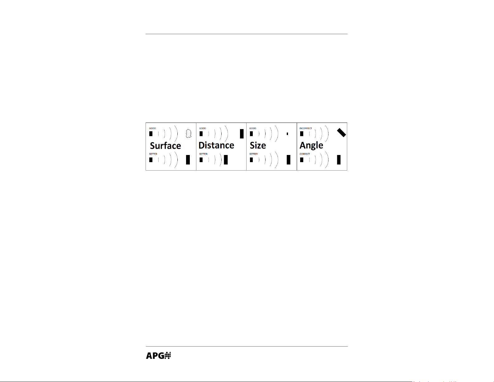
Ultrasonic sensors use a transducer to transmit bursts of ultrasonic sound
waves. Each burst contains a series of pulsed sound waves that emit in the
shape of a cone, refl ect off the target, and are detected by the sensor. The # me
required for the sound waves to travel to and from the target is converted into
a distance measurement by the sensor. Ultrasonic sensing is aff ected by several
factors including the target surface, distance, size, and angle. The following
considera# ons will help ensure the best possible target condi# ons.
Surface
The ideal target surface is hard and smooth. This type of surface will refl ect a
greater amount of signal than a so$ or uneven surface. Sound wave absorbent
materials, such as granules and powders, will reduce the opera# ng range of the
sensor and decrease measurement accuracy.
Distance
Sound wave a% enua# on increases as the distance traveled increases.
Therefore, targets at longer ranges require be% er refl ec# ve characteris# cs than
targets that are closer to the sensor.
Size
A large object will have a greater surface area to refl ect the signal than a
smaller one. Therefore, a large target will be detected at a greater distance
than a small target. The surface area recognized as the target will generally be
the por# on closest to the sensor.
Page 5

Rev. B1, 5/13 MNU Series Ultrasonic Sensors
5
Automa! on Products Group, Inc.
APG...Providing tailored solu• ons for measurement applica• ons
Tel: 1/888/525-7300 • Fax: 1/435/753-7490 • www.apgsensors.com • sales@apgsensors.com
Angle
The inclina! on of the object’s surface in rela! on to the sensor face will aff ect
the strength of the refl ected sound waves. Surfaces perpendicular to the
sensor will refl ect more signal directly back to the sensor. If a surface is more
than a few degrees off perpendicular, enough of the signal will be refl ected
away from the sensor that the target will not be detected. Generally speaking,
a target angle greater than 5 degrees off perpendicular will not be detected.
The target angle becomes increasingly cri! cal as the distance to the target
increases.
Environmental Condi! ons
Temperature, humidity, vapors, dust, and pressure can aff ect the sensor’s
performance. APG ultrasonic sensors are designed to compensate for many of
these condi! ons. However, if the condi! ons are extreme, sensor performance
can be degraded enough to require the use of a longer-range sensor than
normal condi! ons would require. Ultrasonic sensors may not be suitable for
applica! ons with heavy chemical vapors (such as solvents or gasoline), heavy
dust or when signifi cant surface foam is present.
Page 6
MNU Series Ultrasonic Sensors Rev. B1, 5/13
6
Automa! on Products Group, Inc.
APG...Providing tailored solu• ons for measurement applica• ons
Tel: 1/888/525-7300 • Fax: 1/435/753-7490 • www.apgsensors.com • sales@apgsensors.com
NOTE: S! lling pipes are an excellent solu! on for liquid level
applica! ons where an unobstructed path to the target is not feasible
(see s! lling pipe moun! ng on page 9 for details).
• When moun! ng outdoors, it’s best to shade the sensor from direct
sunlight. Direct sunlight can warm the sensor housing above the ambient
temperature causing false temperature readings and overcompensa! on by
the sensor.
• Installa! on
Proper sensor moun! ng is cri! cal for successful opera! on of an ultrasonic
sensor. Using the following guidelines can help ensure trouble free installa! on
and opera! on:
• Ensure that the sensor face is perpendicular to the target surface. If the
target is more than a few degrees off perpendicular, it may not be
detected. Targets at greater distances will require more precise sensor
alignment.
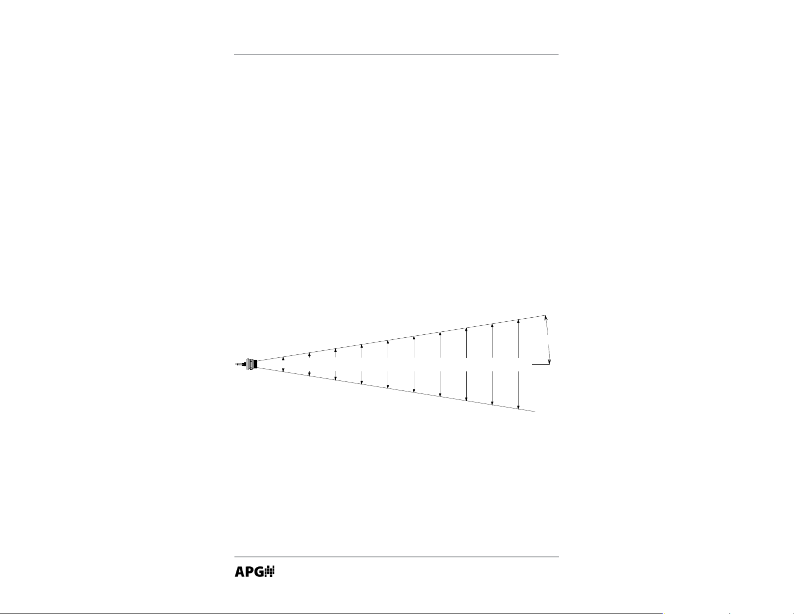
• Mount the sensor in a loca! on that provides an unobstructed column
of air from the sensor to the target. The required width of the air
column depends on several factors, including the angle and refl ec! ve
characteris! cs of any poten! al targets on the edge of the column, the
sensi! vity se$ ng of the sensor, the maximum distance to the target, and
the refl ec! ve characteris! cs of the target itself. Generally speaking a 3 to 4
foot diameter unobstructed column is suffi cient even at longer ranges.
11.4
in
.
1
9
i
n
.
2
2
.
8
in
.
2
6
.6
in
.
30.
4
i
n
.
3
4
.
2
in
.
3
8
i
n
.
3
.
8
in
.
7
.
6
i
n
.
9
°
1
5
.
2
i
n
.
2
ft.
4
f
t
.
3
f
t
.
5
f
t
.
6
f
t
.
7ft
.
8
f
t
.
9
f
t
.
1
0
f
t
.
1
f
t.
dLJƉŝĐĂůďĞĂŵƐƉƌĞĂĚŽĨĂƐĞŶƐŽƌŽƉĞƌĂƟŶŐĂƚŵĂdžŝŵƵŵƐĞŶƐŝƟǀŝƚLJ
Page 7
Rev. B1, 5/13 MNU Series Ultrasonic Sensors
7
Automa! on Products Group, Inc.
APG...Providing tailored solu• ons for measurement applica• ons
Tel: 1/888/525-7300 • Fax: 1/435/753-7490 • www.apgsensors.com • sales@apgsensors.com
• Always mount above the highest an! cipated target level by at least the
published minimum blanking distance. If a target enters into the blanking
area, error in the detec! on will occur. It is always advisable to allow for
suffi cient headroom to ensure that the target does not enter the blanking
area.
• Generally it is advisable to mount the sensor away from any vessel fi ll
spouts. However, if heavy foam is expected, it is o$ en helpful to mount the
Sensor near a fi ll spout where the foam is being dispersed.
• Avoid moun! ng the sensor in the direct center of a tank with a signifi cantly
domed top. A domed top can act as parabolic dish, amplifying small
undesired signals that may be present inside the tank.
• Avoid moun! ng the sensor in close proximity to tank walls, especially on
tanks with corrugated walls or in applica! ons where product buildup on
the tank walls may occur.
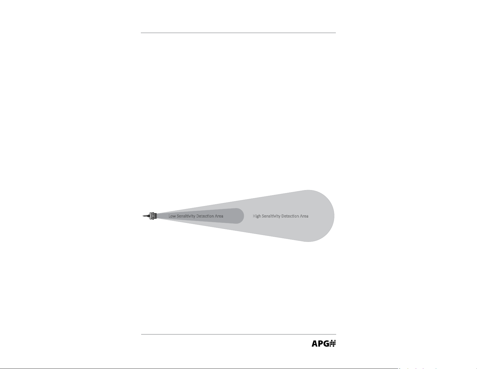
>Žǁ^ĞŶƐŝƟǀŝƚLJĞƚĞĐƟŽŶƌĞĂ,ŝŐŚ^ĞŶƐŝƟǀŝƚLJĞƚĞĐƟŽŶƌĞĂ
Page 8
MNU Series Ultrasonic Sensors Rev. B1, 5/13
8
Automa! on Products Group, Inc.
APG...Providing tailored solu• ons for measurement applica• ons
Tel: 1/888/525-7300 • Fax: 1/435/753-7490 • www.apgsensors.com • sales@apgsensors.com
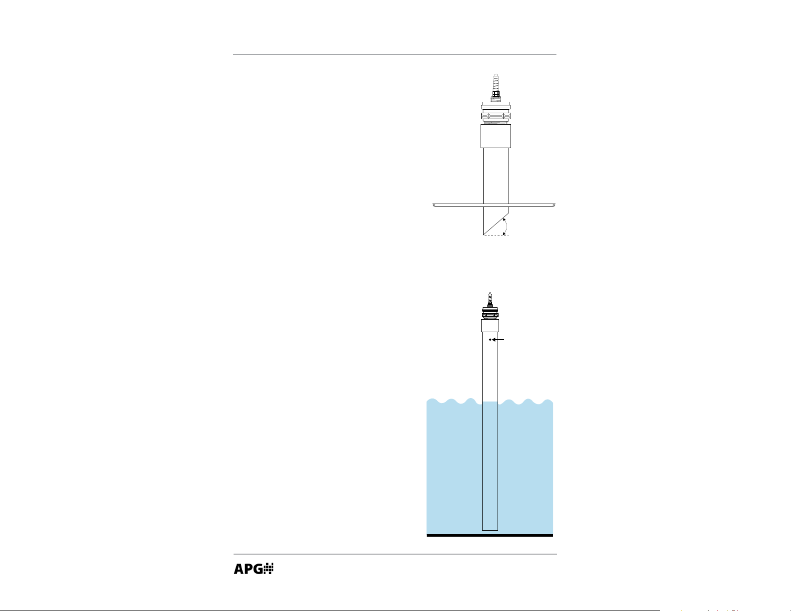
Stand Pipe Moun! ng
Stand pipes are used to provide headroom at
the top of a tank when the target is expected
to come closer to the sensor than the
minimum blanking distance. It’s very cri! cal
that the stand pipe be installed perpendicular
to the target. This is especially important
on longer range applica! ons. The pipe must
have smooth walls (no joints) and no burs or
obstruc! ons. If possible, cut the end of the
pipe at a 10°-45° angle (see drawing). Use
the largest diameter pipe and shortest length
possible. As a general rule, the diameter of
the pipe should be 1/2 the length. The pipe
ID must remain the same through it’s en! re
length.
S! lling Pipe Moun! ng
S! lling pipes provide access to diffi cult areas
and help eliminate problems with foam.
The pipe must have smooth walls (no burs
or joints). Because the sound waves will
concentrate and propagate down the inside
walls of the tube, any irregulari! es on the
tube walls may produce echo returns and
cause false readings. S! lling pipes are limited
to liquid targets that will not leave heavy
deposits on the tube walls. Because the
sound waves are confi ned inside the pipe,
it is usually necessary to greatly reduce the
sensors sensi! vity and pulses se$ ngs. A vent
hole must be provided at the top of the pipe.
Be sure to keep the vent hole inside of the
blanking area.
Cut at angle
when possible
Vent Hole
Page 9
Rev. B1, 5/13 MNU Series Ultrasonic Sensors
9
Automa! on Products Group, Inc.
APG...Providing tailored solu• ons for measurement applica• ons
Tel: 1/888/525-7300 • Fax: 1/435/753-7490 • www.apgsensors.com • sales@apgsensors.com
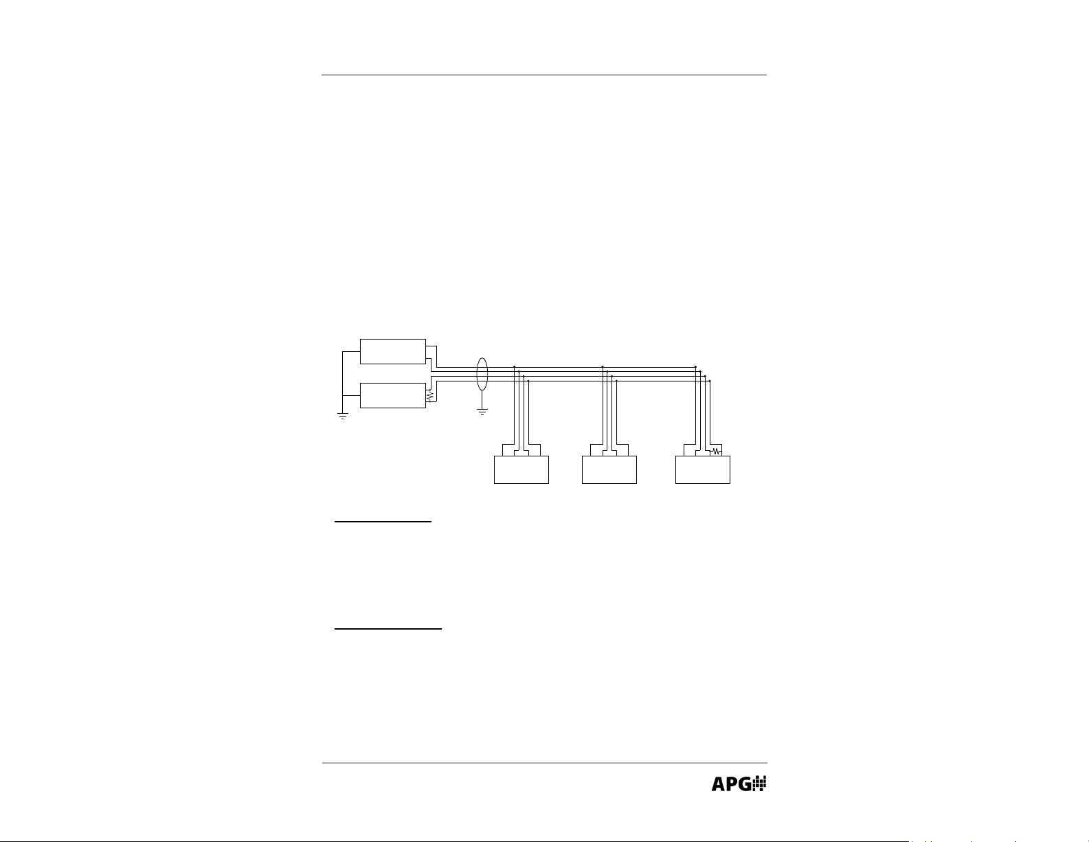
• Wiring
Always use shielded cable. It is recommended that twisted-pair cable be used
between sensors when connec! ng mul! ple sensors to the Modbus network.
NOTE:
Always use a high quality power supply that will deliver clean, stable
voltage.
The MNU series sensors are wired in a daisy-chain confi gura! on, as shown
below. Each sensor should be connected individually and assigned a unique
address before wiring the sensor into the Modbus network.
Power
Supply
Master
Device
RS-485 A
RS-485 B
Vdc
Vdc
+
-
Sensor 1
V+ V- A B
Sensor 2
V+ V- A B
Sensor 3
V+ V- A B
Use Shielded Cable
120 Ohm
Terminating
Resistor
120 Ohm
Terminating
Resistor
Modbus Daisy-Chain Wiring
Mirco Connector:
Pin 1 (Brown) +24 VDC
Pin 2 (White) RS-485 A
Pin 3 (Blue) DC Common
Pin 4 (Black) RS-485 B
4-Conductor Cable:
Red +24 VDC
Black DC Common
White RS-485 A
Green RS-485 B
Page 10

MNU Series Ultrasonic Sensors Rev. B1, 5/13
10
Automa! on Products Group, Inc.
APG...Providing tailored solu• ons for measurement applica• ons
Tel: 1/888/525-7300 • Fax: 1/435/753-7490 • www.apgsensors.com • sales@apgsensors.com
• Sensor Communica! ons
The MNU sensor u! lizes standard Modbus RTU protocol (RS-485). The MNU
sensor can only operate as a slave device. For more informa! on about Modbus
RTU, please visit www.modbus.org.
The MNU sensor will transmit at (allow a minimum delay of 300 ms between
transac! ons):
9600 bps
8 data bits
No parity
1 stop bit
Input Registers (0x04):
Register Returned Data
30300 Raw Distance/Level Reading (in mm, unsigned)
30302 Temperature Reading (in
0
C, signed)
30303-30304 Calculated Reading (in selected units, without decimal place)
NOTE: the Calculated Reading will be returned as a whole number. In order
to a" ain the true result, the Decimal Place se# ng must be taken into account. Refer to Decimal Place se# ng on page 21 for more informa! on.
Holding Registers (0x03):
Register Func! on Value Range
40400 Device Address 1 to 255
40401 Units 1 to 3
40402 Applica! on Type 0-10
40403 Volume Units 0 to 6
40404 Decimal Place 0 to 3
40405 Max Distance 0 to 10364 mm
40406 Full Distance 0 to 10364 mm
40407 Empty Distance 0 to 10364 mm
Page 11

Rev. B1, 5/13 MNU Series Ultrasonic Sensors
11
Automa! on Products Group, Inc.
APG...Providing tailored solu• ons for measurement applica• ons
Tel: 1/888/525-7300 • Fax: 1/435/753-7490 • www.apgsensors.com • sales@apgsensors.com
(con! nued)
Register Func! on Value Range
40408 Sensi! vity 0 to 100
40409 Pulses 0 to 20
40410 Blanking 0 to 10364 mm
40411 Gain Control 0 to 4
40412 Averaging 0 to 100
40413 Filter Window 0 to 10364 mm
40414 Out of Range Samples 0 to 255
40415 Sample Rate 50 to 1000 msec.
40416 Mul! plier 1 to 1999
40417 Off set +/- 10364 mm
40418-40419 reserved n/a
40420 Temperature Compensa! on 0 = off , 1 = on
40421-40435 reserved n/a
40436-40437 Parameter 1 Data 0 to 100,000 mm
40438-40439 Parameter 2 Data 0 to 100,000 mm
40440-40441 Parameter 3 Data 0 to 100,000 mm
40442-40443 Parameter 4 Data 0 to 100,000 mm
40444-40445 Parameter 5 Data 0 to 100,000 mm
Page 12
MNU Series Ultrasonic Sensors Rev. B1, 5/13
12
Automa! on Products Group, Inc.
APG...Providing tailored solu• ons for measurement applica• ons
Tel: 1/888/525-7300 • Fax: 1/435/753-7490 • www.apgsensors.com • sales@apgsensors.com
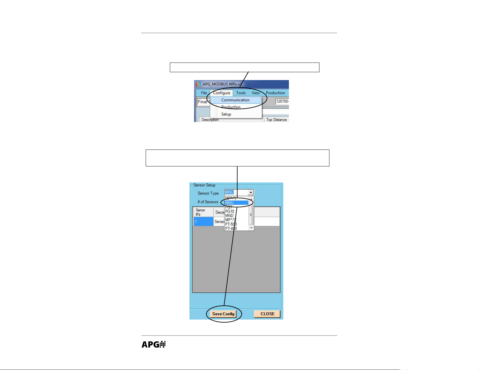
Confi guring So# ware Communica! ons
Step 2: select “MNU” from the Sensor Type menu, then click the “Save
Confi g” bu" on at the bo" om of the screen.
Step 1: select “Communica# on” from the “Confi gure” menu.
Page 13

Rev. B1, 5/13 MNU Series Ultrasonic Sensors
13
Automa! on Products Group, Inc.
APG...Providing tailored solu• ons for measurement applica• ons
Tel: 1/888/525-7300 • Fax: 1/435/753-7490 • www.apgsensors.com • sales@apgsensors.com
Step 3: set the mode of communica! on by selec! ng the .
Select the appropriate Comm Port when using direct serial communica! ons.
Check the “USB Communica! ons (RST-6001)” box when using the RST-6001
communica! ons module.
OR
Page 14

MNU Series Ultrasonic Sensors Rev. B1, 5/13
14
Automa! on Products Group, Inc.
APG...Providing tailored solu• ons for measurement applica• ons
Tel: 1/888/525-7300 • Fax: 1/435/753-7490 • www.apgsensors.com • sales@apgsensors.com
Step 2: change the “Sensor #”
boxes to match the address’ of
the target sensors.
Step 3: Change the Descrip! on labels as desired. The Descrip! on is
used to diff eren! ate between sensors in other areas of the so$ ware.
Step 4: Click “Save
Confi g” then “Close”.
Step 1: select the total number
of sensors you wish to read.
Confi guring So# ware Communica! ons for Mul! ple Sensors
(con! nued)
Page 15

Rev. B1, 5/13 MNU Series Ultrasonic Sensors
15
Automa! on Products Group, Inc.
APG...Providing tailored solu• ons for measurement applica• ons
Tel: 1/888/525-7300 • Fax: 1/435/753-7490 • www.apgsensors.com • sales@apgsensors.com
START
Step 6: Click on a sensor descrip! on to access that sensor’s parameters.
Refer to “Using the So" ware Programming Window” on the next page
for informa! on on adjus! ng sensor parameters.
Step 5: Click on “Start”. The sensor readings should
populate as the so" ware cycles through each sensor.
Page 16

MNU Series Ultrasonic Sensors Rev. B1, 5/13
16
Automa! on Products Group, Inc.
APG...Providing tailored solu• ons for measurement applica• ons
Tel: 1/888/525-7300 • Fax: 1/435/753-7490 • www.apgsensors.com • sales@apgsensors.com
Click on the desired sensor descrip! on to
open that sensor’s programming window.
The register values should automa! cally populate. If not, click
“Receive All” to retrieve the register values from the sensor.
Using the So" ware Programming Window
Sensor readings are displayed
in the Input Registers table.
(con! nued on next page)
Page 17

Rev. B1, 5/13 MNU Series Ultrasonic Sensors
17
Automa! on Products Group, Inc.
APG...Providing tailored solu• ons for measurement applica• ons
Tel: 1/888/525-7300 • Fax: 1/435/753-7490 • www.apgsensors.com • sales@apgsensors.com
To send all the register values as
currently listed, click “Send All”
A green window
indicates successful
communica! on.
A yellow window
indicates a communi-
ca! on failure.
To change an individual parameter, click on the value
you wish to change, enter the desired value, then click
the adjacent “Send” bu" on to implement the change.
To retrieve the register values saved
in a sensor, click “Receive All”
1500
Send
1500
Send
150000
Send
A red window indi-
cates a value outside
the allowable limits
for the parameter.
Page 18

MNU Series Ultrasonic Sensors Rev. B1, 5/13
18
Automa! on Products Group, Inc.
APG...Providing tailored solu• ons for measurement applica• ons
Tel: 1/888/525-7300 • Fax: 1/435/753-7490 • www.apgsensors.com • sales@apgsensors.com
• Parameter Descrip! ons
Device Address (1 to 255) (40400)
Each device within the Modbus network must be assigned a unique address.
Each MNU sensor should be connected to the network individually and assigned an address. By default the each sensor is set to address 1.
Units (1 to 3) (40401)
Determines the unit of measure for the Calculated Reading (input registers
30303-30304) when in Applica! on Types 1, 2 or 7 (see below).
Applica! on Type (0 to 11) (40402)
Determines how the sensor calculates the readings.
Applica! on Type 0: Distance to target
(measurement result in register 30300)
Register Func! on Value Range
40401 Units 1 to 3
40402 Applica! on Type 0
40404 Decimal Place 0 to 3
40405 Max Distance 0 to 10364 mm
Applica! on Type 1: Depth of level
(measurement result in register 30300)
Register Func! on Value Range
40401 Units 1 to 3
40402 Applica! on Type 1
40404 Decimal Place 0 to 3
40405 Max Distance ≥ Empty Distance
40406 Full Distance Typically = Blanking Distance
40407 Empty Distance 0 to 10364 mm
Distance
Level
Page 19

Rev. B1, 5/13 MNU Series Ultrasonic Sensors
19
Automa! on Products Group, Inc.
APG...Providing tailored solu• ons for measurement applica• ons
Tel: 1/888/525-7300 • Fax: 1/435/753-7490 • www.apgsensors.com • sales@apgsensors.com
Applica! on Type 2: Volume of cylindrical tank with or without hemispherical bo" om (measurement result in register 30303-30304)
Register Func! on Value Range
40402 Applica! on Type 2
40403 Volume Units 1 to 7
40404 Decimal Place 0 to 3
40405 Max Distance # Empty Distance
40406 Full Distance Typically = Blanking Distance
40407 Empty Distance 0 to 10364 mm
40436-40437 Tank Diameter 0 to 100,000 mm
40438-40439 Bo" om Radius 0 to 100,000 mm
NOTE: for fl at bo" om tanks, set the Bo" om Radius to 0.
Diameter
Empty
Distance
ŽƩŽŵ
Radius
Full
Distance
or
Page 20

MNU Series Ultrasonic Sensors Rev. B1, 5/13
20
Automa! on Products Group, Inc.
APG...Providing tailored solu• ons for measurement applica• ons
Tel: 1/888/525-7300 • Fax: 1/435/753-7490 • www.apgsensors.com • sales@apgsensors.com
Applica! on Type 3: Volume of cylindrical tank with conical bo" om
(measurement result in register 30303-30304)
Register Func! on Value Range
40402 Applica! on Type 3
40403 Volume Units 1 to 7
40404 Decimal Place 0 to 3
40405 Max Distance # Empty Distance
40406 Full Distance Typically = Blanking Distance
40407 Empty Distance 0 to 10364 mm
40436-40437 Tank Diameter 0 to 100,000 mm
40438-40439 Cone Diameter 0 to 100,000 mm
40440-40441 Cone Length 0 to 100,000 mm
Diameter
Full
Distance
Empty
Distance
Cone
Length
Cone
Diameter
Page 21

Rev. B1, 5/13 MNU Series Ultrasonic Sensors
21
Automa! on Products Group, Inc.
APG...Providing tailored solu• ons for measurement applica• ons
Tel: 1/888/525-7300 • Fax: 1/435/753-7490 • www.apgsensors.com • sales@apgsensors.com
Applica! on Type 4: Volume of rectangular tank with or without chute
bo" om (measurement result in register 30303-30304)
Register Func! on Value Range
40402 Applica! on Type 4
40403 Volume Units 1 to 7
40404 Decimal Place 0 to 3
40405 Max Distance # Empty Distance
40406 Full Distance Typically = Blanking Distance
40407 Empty Distance 0 to 10364 mm
40436-40437 Tank X 0 to 100,000 mm
40438-40439 Tank Y 0 to 100,000 mm
40440-40441 Chute X 0 to 100,000 mm
40442-40443 Chute Y 0 to 100,000 mm
40444-40445 Chute Length 0 to 100,000 mm
Tank X
Chute
Length
Tank Y
Empty
Distance
Full
Distance
or
Chute Y
Chute X
Page 22

MNU Series Ultrasonic Sensors Rev. B1, 5/13
22
Automa! on Products Group, Inc.
APG...Providing tailored solu• ons for measurement applica• ons
Tel: 1/888/525-7300 • Fax: 1/435/753-7490 • www.apgsensors.com • sales@apgsensors.com
Applica! on Type 5: Volume of horizontal cylindrical tank with or without
hemispherical ends (measurement result in register 30303-30304)
Register Func! on Value Range
40402 Applica! on Type 5
40403 Volume Units 1 to 7
40404 Decimal Point 0 to 3
40405 Max Distance ≥ Empty Distance
40406 Full Distance Typically = Blanking Distance
40407 Empty Distance 0 to 10364 mm
40436-40437 Tank Length 0 to 100,000 mm
40438-40439 Tank Diameter 0 to 100,000 mm
40440-40441 End Radius 0 to 100,000 mm
Diameter
Length
Empty
Distance
End
Radius
Full
Distance
Page 23

Rev. B1, 5/13 MNU Series Ultrasonic Sensors
23
Automa! on Products Group, Inc.
APG...Providing tailored solu• ons for measurement applica• ons
Tel: 1/888/525-7300 • Fax: 1/435/753-7490 • www.apgsensors.com • sales@apgsensors.com
Applica! on Type 6: Volume of spherical tank
(measurement result in register 30303-30304)
Register Func! on Value Range
40402 Applica! on Type 6
40403 Volume Units 1 to 7
40404 Decimal Point 0 to 3
40405 Max Distance ≥ Empty Distance
40406 Full Distance Typically = Blanking Distance
40407 Empty Distance 0 to 10364 mm
40436-40437 Tank Diameter 0 to 100,000 mm
Empty
Distance
Diameter
Full
Distance
Page 24

MNU Series Ultrasonic Sensors Rev. B1, 5/13
24
Automa! on Products Group, Inc.
APG...Providing tailored solu• ons for measurement applica• ons
Tel: 1/888/525-7300 • Fax: 1/435/753-7490 • www.apgsensors.com • sales@apgsensors.com
Applica! on Type 7: Pounds
Allows the user to apply a conversion mul! plier to the calculated level reading.
(measurement result in register 30303-30304)
NOTE: the decimal place for the Mul! plier is always assumed to be in the
thousands posi! on, therefore a se" ng of 206250 = 206.250 actual mul! plier.
Example: suppose the product in a tank weighs 206.25 pounds for every
inch of level. Assuming the Units are set to inches (Units = 2), the Mul! plier
would be 206250.
Register Func! on Value Range
40401 Units 1 to 3
40402 Applica! on Type 7
40404 Decimal Place 0 to 3
40405 Max Distance ≥ Empty Distance
40406 Full Distance Typically = Blanking Distance
40407 Empty Distance 0 to 10364 mm
40436-40437 Mul! plier 0 to 1000000 (1000 = 1.000)
Page 25

Rev. B1, 5/13 MNU Series Ultrasonic Sensors
25
Automa! on Products Group, Inc.
APG...Providing tailored solu• ons for measurement applica• ons
Tel: 1/888/525-7300 • Fax: 1/435/753-7490 • www.apgsensors.com • sales@apgsensors.com
Applica! on Type 9: Volume of ver! cal oval tank
(measurement result in register 30303-30304)
Register Func! on Value Range
40402 Applica! on Type 9
40403 Volume Units 1 to 7
40404 Decimal Place 0 to 3
40405 Max Distance ≥ Empty Distance
40406 Full Distance Typically = Blanking Distance
40407 Empty Distance 0 to 10364 mm
40436-40437 Tank Length 0 to 100,000 mm
40438-40439 Tank Depth 0 to 100,000 mm
40440-40441 Tank Width 0 to 100,000 mm
Full
Distance
Empty
Distance
Depth
Length
Width
Page 26

MNU Series Ultrasonic Sensors Rev. B1, 5/13
26
Automa! on Products Group, Inc.
APG...Providing tailored solu• ons for measurement applica• ons
Tel: 1/888/525-7300 • Fax: 1/435/753-7490 • www.apgsensors.com • sales@apgsensors.com
Applica! on Type 10: Volume of horizontal oval tank
(measurement result in register 30303-30304)
Register Func! on Value Range
40402 Applica! on Type 10
40403 Volume Units 1 to 7
40404 Decimal Place 0 to 3
40405 Max Distance ≥ Empty Distance
40406 Full Distance Typically = Blanking Distance
40407 Empty Distance 0 to 10364 mm
40436-40437 Tank Length 0 to 100,000 mm
40438-40439 Tank Depth 0 to 100,000 mm
40440-40441 Tank Width 0 to 100,000 mm
Length
Width
Depth
Empty
Distance
Full
Distance
Page 27

Rev. B1, 5/13 MNU Series Ultrasonic Sensors
27
Automa! on Products Group, Inc.
APG...Providing tailored solu• ons for measurement applica• ons
Tel: 1/888/525-7300 • Fax: 1/435/753-7490 • www.apgsensors.com • sales@apgsensors.com
Applica! on Type 11: Curve Fit (Strapping Chart)
Allows the sensor to mimic a tank strapping chart by using a 3rd degree polynomial equa! on to produce a “curve fi t” approxima! on.
(measurement result in register 30303-30304)
Register Func! on Value Range
40401 Units 1 to 3
40402 Applica! on Type 11
40404 Decimal Place 0 to 3
40406 Full Distance Typically = Blanking
40407 Empty Distance 0 to 10364 mm
40436-40437 Parameter 1 0 to 100,000 mm
40438-40439 Parameter 2 0 to 100,000 mm
40440-40441 Parameter 3 0 to 100,000 mm
40442-40443 Parameter 4 0 to 100,000 mm
Open the APG Modbus so# ware and select “Strapping Chart” from the “Tools”
menu.
Enter the desired data points
into the table.
Use the “Load” bu$ on to recall a previously saved table.
Import data from an electronic
document by copying the data
and then using the “Paste”
bu$ on to populate the table.
OR
OR
Page 28

MNU Series Ultrasonic Sensors Rev. B1, 5/13
28
Automa! on Products Group, Inc.
APG...Providing tailored solu• ons for measurement applica• ons
Tel: 1/888/525-7300 • Fax: 1/435/753-7490 • www.apgsensors.com • sales@apgsensors.com
Once the all data points have been entered, click the “Calculate” bu! on to
determine the values required for the “curve fi t” calcula# on.
Click the “Save to Sensor” bu! on to populate the appropriate Holding Resister
fi elds (see below) and close the Strapping Chart window.
Click the “Send All” bu! on at the bo! om of the Holding Register page to write
the curve fi t values to the sensor.
NOTE: before clicking “Calculate” ensure that
there is only one empty row following the last
line of data (as shown). Use the keyboard
“Delete”key to remove any addi# on empty rows.
Page 29

Rev. B1, 5/13 MNU Series Ultrasonic Sensors
29
Automa! on Products Group, Inc.
APG...Providing tailored solu• ons for measurement applica• ons
Tel: 1/888/525-7300 • Fax: 1/435/753-7490 • www.apgsensors.com • sales@apgsensors.com
Volume Units (0 to 6) (40403)
Determine the unit of measure for the volumetric Applica! on Types.
1 = Cubic Feet
4 = Cubic Meters 7 = Barrels
2 = Million Cubic Feet 5 = Liters
3 = Gallons 6 = Cubic Inches
Decimal Place (0 to 3) (40404)
Used to set the number of decimal places included in the Calculated Reading.
The Calculated Reading will always be returned as a whole number.
Example: a Calculated Reading of 1126.658 (gallons, " 3, etc.) will be returned
as follows:
Decimal Place = 0 Volume = 1127 (rounded to nearest whole number)
Decimal Place = 1 Volume = 11267 (divide by 10 to get true result)
Decimal Place = 2 Volume = 112666 (divide by 100 to get true result)
Decimal Place = 3 Volume = 1126658 (divide by 1000 to get true result)
Maximum Distance (0 to 10364 mm) (40405)
Sets the distance (beginning from the sensor face) to the point where the sensor will stop looking for target signals. Targets detected beyond the Maximum
Distance value will be ignored by the sensor.
Full Distance (0 to 10364 mm) (40406)
Sets the distance (beginning from the sensor face) to the point where the tank
is considered full.
Empty Distance (0 to 10364 mm) (40407)
Sets the distance (beginning from the sensor face) to the point where tank is
considered empty. This will typically be the same as the tank depth unless the
sensor is mounted on a stand pipe.
Page 30

MNU Series Ultrasonic Sensors Rev. B1, 5/13
30
Automa! on Products Group, Inc.
APG...Providing tailored solu• ons for measurement applica• ons
Tel: 1/888/525-7300 • Fax: 1/435/753-7490 • www.apgsensors.com • sales@apgsensors.com
Sensi! vity (0 to 100%) (40408)
Controls the level of amplifi ca" on applied the returning target echoes (signals).
The sensi" vity se# ng is expressed as a percentage; 0 to 100%. When operating in Autosense mode, the Sensi" vity se# ng acts as an upper limit constraint
(refer to Gain Control below for more informa" on on Autosense).
Pulses (0 to 20) (40409)
Controls the number of sound wave pulses being sent in each ultrasonic
burst. The greater the number of pulses, the stronger the transmi$ ed signal.
When opera" ng in Autosense mode, the Pulses se# ng acts as an upper limit
constraint (refer to Gain Control below for more informa" on on Autosense).
Blanking (0 to 10364 mm) (40410)
Sets the distance, beginning at the sensor face, to the point where the sensor
will begin looking for target signals. All targets closer than the blanking distance
will be ignored. The blanking should never be set to less than the minimum
range specifi ca" on of the sensor. If the target enters the blanking area, errant
readings will occur.
Gain Control (0 = Manual Mode; 1 = Autosense Mode) (40411)
Determines how the sensor applies gain (amplifi ca" on) to returning target
echoes. In Manual mode the Sensi" vity and Pules se# ngs are applied as
a sta" c values. In Autosense Mode, the sensor self-adjusts the Pulses and
Sensi" vity levels (within the bounds of their respec" ve se# ngs) in order to
op" mize the signal level.
Averaging (1 to 20) (40412)
Defi nes the number of readings that will be averaged together to become
the Calculated Value. Each qualifi ed reading (see Filter Window and Out of
Range Samples on next page) is placed into a fi rst-in, fi rst-out (FIFO) buff er
and averaged with previous readings. A higher Averaging se# ng will result in
smoother readings, but will also slow the response to rapid target changes.
Page 31

Rev. B1, 5/13 MNU Series Ultrasonic Sensors
31
Automa! on Products Group, Inc.
APG...Providing tailored solu• ons for measurement applica• ons
Tel: 1/888/525-7300 • Fax: 1/435/753-7490 • www.apgsensors.com • sales@apgsensors.com
Filter Window (0 to 10364 mm) (40413)
Sets the width of the target acceptance window. The target acceptance
window is a zone, centered around the current target reading, within which
any target detected will be considered legi! mate and fi gured into the averaging
buff er. Any target detected outside of the Window will be considered “out of
range” and will be ignored based on the se$ ng in the Out of Range Samples
parameter (see below). The Filter Window extends in both direc! ons from the
current target reading. For example, if the sensor is detec! ng a target at 5 % .
and the Filter Window is set at 1 % ., then any target detected between 4 % . and
6 % . will be accepted.
Out of Range Samples (1 to 255) (40414)
Determines the number of consecu! ve target readings that fall outside of the
acceptance window before the “out of range” target is recognized as being
legi! mate and fi gured into the averaging buff er. For example, suppose the
Out Of Range Samples is set to 10. If a target is suddenly detected outside
of the acceptance window, it will be ignored un! l it has been detected for 10
consecu! ve samples, at which point it will be qualifi ed as a legi! mate target. If
the “out of range” target was detected for only 9 consecu! ve samples before
moving out of the sensing area, it would never be acknowledged as a target and
the reading would stay with the last qualifi ed target sample.
Sample Rate (50 to 1000 msec) (40415)
Sets the interval between target readings. Op! ons allow rates from 50 to
1000 msec. A higher Sample Rate will result in a more rapid response to target
movements. Lowering the Sample Rate will help increase sensor lifespan and
decrease the chance of detec! ng errant echoes. It is highly recommended that
the Sample Rate be set only as fast as is necessary for the applica! on. A sample
rate of 500 to 1000 msec. is usually appropriate for slow moving level sensing
applica! ons.
Page 32

MNU Series Ultrasonic Sensors Rev. B1, 5/13
32
Automa! on Products Group, Inc.
APG...Providing tailored solu• ons for measurement applica• ons
Tel: 1/888/525-7300 • Fax: 1/435/753-7490 • www.apgsensors.com • sales@apgsensors.com
Mul! plier (0 to 1999) (40416)
Sets the conversion Mul! plier that will be applied to the sensor readings. The
default is 1000 (see note below) and typically does not need to be adjusted.
However, since the speed of sound is not constant through all environments,
the mul! plier parameter allows the user to adjust for varia! ons in atmosphere
when maximum accuracy is required.
NOTE: the decimal place for the Mul! plier is always assumed to be in the
thousands posi! on, therefore a se" ng of 1025 = 1.025 actual mul! plier.
Off set (-10364 to 10364 mm) (40417)
Used to adjust the zero reference point of the sensor. When the Off set is set to
0, the zero reference of the sensor is at the face of the transducer. Se" ng the
Off set to a nega! ve number will move the zero reference backward (behind the
sensor face), while a posi! ve se" ng will move the reference forward (in front
of the sensor face).
Temperature Compensa! on (0 = Off , 1 = On) (40420)
Used to enable or disable the internal temperature compensa! on of the sensor.
Enabling the internal temperature compensa! on can reduce the eff ects of
temperature changes by 50% or more, depending on the temperature gradient
through the sensing range.
Parameter Data (0 to 100,000 mm) (40436 to 40445)
The Parameter Data registers are used to enter tank dimension or conversion
mul! pliers for all the volumetric Applica! on Types (types 2-10).
Page 33

Rev. B1, 5/13 MNU Series Ultrasonic Sensors
33
Automa! on Products Group, Inc.
APG...Providing tailored solu• ons for measurement applica• ons
Tel: 1/888/525-7300 • Fax: 1/435/753-7490 • www.apgsensors.com • sales@apgsensors.com
•Web Alarming (40430 to 40435)
When the MNU is interfaced with an LOE or RST-5002 web-enabled master
device, it can be confi gured to generate website alarms via levelandfl ow.com
(refer to the LOE or RST-5002 user manual for more informa# on about website
alarms and using levelandfl ow.com).
Trip Alarm 1 (40430) or Alarm 2 (40433) Distance
Sets the level (in mm), beginning the bo$ om of the stem, to the fi rst (lowest)
actua# on point (refer to next page for more informa# on).
Trip Alarm 1 Window (40431 or 40434)
Sets the level (in mm), beginning from the Trip Distance loca# on, to the secondary actua# on point (refer to next page for more informa# on).
Trip Alarm 1 Type (40432 or 40435)
Determines the opera# onal logic performed by the Trip Alarm (refer to chart on
next page for more informa# on).
Confi guring Trip Alarm Types for Website Alarming:
(refer to Trip Types chart on next page)
Placing a “1” in front of any of the Trip Types designates an ac# ve trip point as
an alarm condi# on. For example; Trip Type 3 would be designated as 13, and
would ini# ate a website alarm whenever the trip is ac# ve (on).
Placing a “2” in front of any of the Trip Types designates an inac# ve trip point as
an alarm condi# on. For Example; Trip Type 3 would be designated as 23, and
would ini# ate a website alarm whenever the trip is inac# ve (off ).
Page 34

MNU Series Ultrasonic Sensors Rev. B1, 5/13
34
Automa! on Products Group, Inc.
APG...Providing tailored solu• ons for measurement applica• ons
Tel: 1/888/525-7300 • Fax: 1/435/753-7490 • www.apgsensors.com • sales@apgsensors.com
Type 6: n/a
Type 7 (Loss of Echo): the relay will ac! vate if the sensor enters a loss of echo condi! on (no targets detected).
Type 8 n/a
Type 9 (Rate of Change): allows the user to defi ne a maximum rate of change (distance over ! me), which if
exceeded will ac! vate an alarm. The Trip Distance parameter is used to defi ne the ! me value, and the Trip
Window parameter is used to defi ne the distance value.
Trip
Distance
Trip
Window
Empty
Distance
Zero Reference
Point
ON
ON
Trip Type 1
;ĞdžĐůƵƐŝǀĞͿ
OFF
(Increasing)
ON
Trip Type 2
(hysteresis near)
OFF
OFF
(Decreasing)
ON
OFF
ON
Trip Type 4
;ŝŶĐůƵƐŝǀĞͿ
OFF
OFF
(Decreasing)
ON
OFF
(Increasing)
Trip Type 5
(hysteresis far)
ON
ONOFF
Trip Type 3
(far)
ON OFF
Trip Type 0
(near)
Page 35

Rev. B1, 5/13 MNU Series Ultrasonic Sensors
35
Automa! on Products Group, Inc.
APG...Providing tailored solu• ons for measurement applica• ons
Tel: 1/888/525-7300 • Fax: 1/435/753-7490 • www.apgsensors.com • sales@apgsensors.com
• Inspec! on and Maintenance
The MNU series sensor requires li! le maintenance, but should be inspec" on
periodically to ensure the sensor remains in good working order. Keep the
sensor clean from heavy buildup on the sensing face. On models equipped
with a micro-connector cable connec" on, ensure that the connec" on is
securely " ghtened and sealed against the elements.
Page 36

MNU Series Ultrasonic Sensors Rev. B1, 5/13
36
Automa! on Products Group, Inc.
APG...Providing tailored solu• ons for measurement applica• ons
Tel: 1/888/525-7300 • Fax: 1/435/753-7490 • www.apgsensors.com • sales@apgsensors.com
• Specifi ca! ons
Opera! ng Range
MNU-5400: 4 to 72 in. (101 to 1829 mm)
MNU-7400: 6 to 144 in. (150 to 3658 mm)
MNU-6400: 10 to 180 in. (178 to 4572 mm)
MNU-2400: 1 to 25 ! . (305 to 7620 mm)
MNU-3400: 1.5 to 40 ! . (458 to 12192 mm)
Opera! ng Voltage: 12-24 Vdc
Opera! onal Current Draw: 35 mA @ 12 Vdc; 20 mA @ 24 Vdc
Housing: PBT/Polycarbonate blend
Moun! ng
MNU-2424, 5424, 6424, 7424: 2 in. NPT
MNU-3434: 3 in. NPT
Transducer Type
MNU-2424, 5424, 6424, 7424: PVDF faced ceramic
MNU-3434: PBT/Polycarbonate faced ceramic
Environmental Ra! ng: NEMA 6P
Sample Rate: 1 to 50 Hz (programmable)
Response Time: Programmable (50 ms minimum)
Resolu! on: 0.1 in. (2.5 mm)
Accuracy: +/- 0.25% of detected range (with no temperature gradient)
Sensor Adjustments: Modbus RTU (RS-485).
Opera! ng Temperature: -30 to 140
0
F (-34 to 60 0C)
Beam Pa# ern: 90 off -axis (maximum)
Electrical Connec! on: 4-conductor twisted-pair cable or 4-pin micro-connector
Frequency
MNU-5424: 170 kHz
MNU-7424: 90 kHz
MNU-6424 & 2424: 69 kHz
MNU-3434: 43 kHz
Page 37

Rev. B1, 5/13 MNU Series Ultrasonic Sensors
37
Automa! on Products Group, Inc.
APG...Providing tailored solu• ons for measurement applica• ons
Tel: 1/888/525-7300 • Fax: 1/435/753-7490 • www.apgsensors.com • sales@apgsensors.com
3.06”
4.5”
3/4” NPT
1” NPT
3.06”
2.0”
4.0”
3/4” NPT
1” NPT
MNU-5414
MNU-5414-M
Page 38

MNU Series Ultrasonic Sensors Rev. B1, 5/13
38
Automa! on Products Group, Inc.
APG...Providing tailored solu• ons for measurement applica• ons
Tel: 1/888/525-7300 • Fax: 1/435/753-7490 • www.apgsensors.com • sales@apgsensors.com
• Dimensions
MNU-2424, 5424, 6424, 7424
3.06”
4.15”
3/4” NPT
2” NPT
3.06”
2.0”
3.6”
3/4” NPT
2” NPT
MNU-2424-M, 5424-M,
6424-M, 7424-M
Page 39

Rev. B1, 5/13 MNU Series Ultrasonic Sensors
39
Automa! on Products Group, Inc.
APG...Providing tailored solu• ons for measurement applica• ons
Tel: 1/888/525-7300 • Fax: 1/435/753-7490 • www.apgsensors.com • sales@apgsensors.com
MNU-3434
3/4” NPT
3” NPT
6”
4.17”
2.0”
3/4” NPT
5.52”
4.17”
3” NPT
MNU-3434-M
Page 40

AUTOMATION
APG...Providing tailored solu• ons
for measurement applica• ons
P R O D U C T S
GROUP, INC.
Automa• on Products Group, Inc.
Tel: 1/888/525-7300
1/435/753-7300
Fax: 1/435/753-7490
e-mail: sales@apgsensors.com
www.apgsensors.com
Automa• on Products Group, Inc.
1025 W. 1700 N.
Logan, UT 84321
 Loading...