

Page 1

PRODUCTS
AUTOMATION
Operator’s Manual
GROUP, INC.
LPU-2428
Loop Powered Ultrasonic Level Sensor
Rev. A3, 11/08
Doc. 9002999
Automation Products Group, Inc.
APG...Providing tailored solutions for measurement applications
Tel: 1/888/525-7300 • Fax: 1/435/753-7490 • www .apgsensors.com • E-mail: sales@apgsensors.com
Page 2

LPU-2428 Rev. A3, 11/08
Table of Contents
Warranty ......................................................................................... 3
Introducing...................................................................................... 4
Understanding Ultrasonics............................................................. 5
Installation ...................................................................................... 7
Hazardous Mounting.................................................................... 8
Wiring............................................................................................ 10
Programming................................................................................ 11
Basic Setup................................................................................. 14
Application Setup....................................................................... 15
4-20 mA Setup ........................................................................... 24
Calibration................................................................................. 25
Advanced ................................................................................... 26
Utilities ...................................................................................... 28
Totalization ................................................................................ 29
Programming Example.............................................................. 29
Specifications ................................................................................ 32
Certificate of Compliance ............................................................ 33
Automation Products Group, Inc.
2
APG...Providing tailored solutions for measurement applications
Tel: 1/888/525-7300 • Fax: 1/435/753-7490 • www.apgsensors.com • sales@apgsensors.com
Page 3

Rev. A3, 11/08 LPU-2428
Warranty and W arranty Restrictions
APG warrants its products to be free from defects of material and workmanship
and will, without charge, replace or repair any equipment found defective upon
inspection at its factory, provided the equipment has been returned,
transportation prepaid, within 24 months from date of shipment from factory .
THE FOREGOING WARRANTY IS IN LIEU OF AND EXCLUDES ALL OTHER
WARRANTIES NOT EXPRESSLY SET FORTH HEREIN, WHETHER
EXPRESSED OR IMPLIED BY OPERATION OF LA W OR OTHER WISE
INCLUDING BUT NOT LIMITED TO ANY IMPLIED W ARRANTIES OF
MERCHANT ABILITY OR FITNESS FOR A P AR TICULAR PURPOSE.
No representation or warranty, express or implied, made by any sales
representative, distributor, or other agent or representative of APG which is not
specifically set forth herein shall be binding upon APG. APG shall not be liable
for any incidental or consequential damages, losses or expenses directly or
indirectly arising from the sale, handling, improper application or use of the
goods or from any other cause relating thereto and APG’s liability hereunder, in
any case, is expressly limited to the repair or replacement (at APG’s option) of
goods.
Warranty is specifically at the factory. Any on site service will be provided at
the sole expense of the Purchaser at standard field service rates.
All associated equipment must be protected by properly rated electronic/
electrical protection devices. APG shall not be liable for any damage due to
improper engineering or installation by the purchaser or third parties. Proper
installation, operation and maintenance of the product becomes the
responsibility of the user upon receipt of the product.
Returns and allowances must be authorized by APG in advance. APG will assign
a Return Material Authorization (RMA) number which must appear on all
related papers and the outside of the shipping carton. All returns are subject to
the final review by APG. Returns are subject to restocking charges as determined
by APG’s “Credit Return Policy”.
Automation Products Group, Inc.
APG...Providing tailored solutions for measurement applications
Tel: 1/888/525-7300 • Fax: 1/435/753-7490 • www .apgsensors.com • sales@apgsensors.com
3
Page 4

LPU-2428 Rev. A3, 11/08
Introducing
The LPU-2428 is a loop-powered ultrasonic sensor. The LPU provides a lowpower, non-contact level measurement solution. These units are completely
sealed and are programmed via an RST -4001 programming module. The module
has 5-tactile switches and a 2 line by 8 charater LCD display to provide the user
feedback in programming and sensor performance data.
Sensor features include:
• Loop powered for low power consumption.
• Remote programming.
• Rugged Kynar transducer housing for harsh environments and high degree
of chemical compatibility.
• Microprocessor-controlled.
• Listed by CSA for operation in Class 1 Division 1 Groups C & D and
Class 1 Zone 0 A Ex ia IIB hazardous areas.
• IP65 rating for outdoor applications.
Automation Products Group, Inc.
4
APG...Providing tailored solutions for measurement applications
Tel: 1/888/525-7300 • Fax: 1/435/753-7490 • www.apgsensors.com • sales@apgsensors.com
Page 5

Rev. A3, 11/08 LPU-2428
detection
area
beam spread
low sensitivity
and
pulses
high sensitivity
and
pulses
Understanding Ultrasonics
Ultrasonic sensors measure distance
using a transducer to send out
ultrasonic bursts. Each burst contains
a series of 1-20 pulsed sound waves
that emit in the shape of a cone, reflect
off the target, and are received by the
sensor. The time required for the sound
burst to travel to and from the target is
converted into a distance measurement
by the sensor.
Ultrasonic sensing is affected by
several factors including the target
surface, distance, size, angle, and the
environment. The following
considerations will help ensure the
best possible target conditions.
Surface
The ideal target surface is hard and smooth and perpendicular to the sensor.
This surface will reflect a greater amount of signal than a soft, sound wave
absorbent surface. A target with poor sound wave reflection characteristics will
reduce the operating distance of the sensor and decrease its accuracy.
Automation Products Group, Inc.
APG...Providing tailored solutions for measurement applications
Tel: 1/888/525-7300 • Fax: 1/435/753-7490 • www .apgsensors.com • sales@apgsensors.com
5
Page 6

LPU-2428 Rev. A3, 11/08
1 ft.
2 ft.
3 ft.
4 ft.
5 ft.
6 ft.
7 ft.
8 ft.
9 ft.
10 ft.
Sensor
Typical Beam Pattern of a Ceramic Transducer
at high sensitivity and power settings.
0.317'
0.634'
0.950' 1.267'
1.584' 1.901' 2.217' 2.534'
2.851'
3.168'
Distance
The shorter the distance from the sensor to an object, the stronger the
returning echo will be. Therefore, as the distance increases, the object requires
better reflective characteristics to return a sufficient echo.
Size
A large object will have a greater surface area to reflect the signal than a
small one, therefore, a large target will be detected at a greater distance than a
small target. The surface area recognized as the target is generally the portion
closest to the sensor.
Angle
The inclination of the object's surface facing the ultrasonic sensor affects the
reflectivity of the object. The portion perpendicular to the sensor returns the
echo. If the entire surface is at a great enough angle, the signal will be reflected
away from the sensor and no echo will be detected. Generally a target at an
angle greater than 5° off perpendicular will not be detected.
Environmental Conditions
T emperature, humidity, gases, dust, and pressure may also affect the sensor’s
performance. APG ultrasonic sensors automatically compensate for many of
these conditions. However, these conditions can degrade the sensor’s
performance enough it may be necessary to use a longer-range sensor than
normal conditions would require.
6
APG...Providing tailored solutions for measurement applications
Tel: 1/888/525-7300 • Fax: 1/435/753-7490 • www.apgsensors.com • sales@apgsensors.com
Automation Products Group, Inc.
Page 7

Rev. A3, 11/08 LPU-2428
DO NOT mount the sensor
where the beam will intersect
objects such as fill streams,
pipes, ladder rungs, wall seams,
or corrugated tank walls.
Installation
The LPU sensor should be mounted so that it has a clear sound path to the
level monitored. Mount the sensor away from tank walls and inlets. The path
should be free from obstructions and as open as possible for the 9° off axis
beam pattern. Follow the guidelines mentioned in "Understanding Ultrasonics".
When using a stand pipe to mount the sensor above the tank, the stand pipe
should be seamless and no longer than 4 inches to provide a smooth path for
the sound waves to propagate into the tank. Seams from couplers, nipples or
gaskets can cause erroneous echoes and degrade the sensors performance.
The LPU can be mounted in a coupler, or flange using the 2” NPT threaded case.
Caution: Do not over tighten! The sensor should be threaded in only hand
tight.
The minimum detection range of the LPU is approximately 1 ft. The sensor
should be mounted to ensure the target does not come closer than the
minimum range or erroneous readings may result.
APG...Providing tailored solutions for measurement applications
Tel: 1/888/525-7300 • Fax: 1/435/753-7490 • www .apgsensors.com • sales@apgsensors.com
Automation Products Group, Inc.
7
Page 8

LPU-2428 Rev. A3, 11/08
Automation Products Group, Inc.
APG...Providing tailored solutions for measurement applications
8
Tel: 1/888/525-7300 • Fax: 1/435/753-7490 • www.apgsensors.com • sales@apgsensors.com
Page 9

Rev. A3, 11/08 LPU-2428
Automation Products Group, Inc.
APG...Providing tailored solutions for measurement applications
Tel: 1/888/525-7300 • Fax: 1/435/753-7490 • www .apgsensors.com • sales@apgsensors.com
9
Page 10

LPU-2428 Rev. A3, 11/08
Wiring
1. Sensor has two wires:
Red - +24V DC
Black - 4-20ma output
2. Connect Red wire to +24V DC supply.
3. Connect Black wire to “Load” (input of PLC or other type of load
that is greater than 150 ohms)
4. To program sensor connect positive terminal of RST to the sensor red wire
and connect the negative terminal to the sensor black wire.
5. To program using the computer software connect USB cable
between the RST-4001 and the computer.
Note: Use the following wiring diagram when connecting to an intrinsically
safe barrier (only required for operation in hazardous locations).
Recommended barrier is the Stahl 9001/51-280-110-141, or equivalent.
10
Automation Products Group, Inc.
APG...Providing tailored solutions for measurement applications
Tel: 1/888/525-7300 • Fax: 1/435/753-7490 • www.apgsensors.com • sales@apgsensors.com
Page 11

Rev. A3, 11/08 LPU-2428
Programming
The LPU is programmed using the RST -4001 programmer via the keypad &
display or the USB interface & computer software.
RST Programming:
The LCD display shows the distance measurement. The display is also used
to view the individual modes and their values when programming.
The LPU has five programming or navigation buttons, LEFT Arrow, RIGHT
Arrow , UP Arrow, DOWN Arrow, and ENTER (I/O). The arrow buttons allow the
user to move through the pages in order to access and change parameters.
Once a parameter has been changed press the I/O to save.
To select a page, press the UP Arrow or DOWN Arrow button until the
desired page is displayed. Press the Right arrow to move into that page. Then
press the UP or DOWN Arrow button to move to the desired parameter. When
the parameter is shown press the RIGHT Arrow button. The display will show
the name of this parameter on the lower line and the current value on the upper
line of the display. To change the parameter’s value, press the UP Arrow or
DOWN Arrow button until the desired value is displayed.
To store or save the changed value, press the I/O button once. At this point,
the parameter value has been saved. The values are stored in nonvolatile
memory, and will not be lost when power is turned off.
Use the provided terminal strip and
resistor to establish communication
with the RST-4001. Follow the wiring
diagram shown on the previous page.
Automation Products Group, Inc.
APG...Providing tailored solutions for measurement applications
Tel: 1/888/525-7300 • Fax: 1/435/753-7490 • www .apgsensors.com • sales@apgsensors.com
11
Page 12

LPU-2428 Rev. A3, 11/08
• Computer Programming
The utility program used for setting up the sensor is supplied on a 3.5 inch
CD. Install the software by running the Windows Installer Package titled,
“Setup”. The installation process will prompt you as needed to complete the
installation. This will load the operating program to your hard drive. The setup
program can be run from the Windows “START” menu “RUN” option by
entering the file location and name, or by going to W indows Explorer, locating
the file and double clicking on “LPU-2428.EXE”. The setup program will create
an “APG” folder under the Windows program menu.
When the program screen comes up, there are several buttons and windows
to view information. The lower right side of the screen contains two windows
indicating the communication status of the sensor and computer. It will indicate
"Sensor NO Communication", or "Sensor Communicating". If an error is
indicated, then check for proper connections. Allow a moment for the
communication to be established while watching the status window to indicate
"Sensor Communicating". If this fails to establish communication, plug the USB
cable into the second port on the back of the computer. After communication is
established, click on the "Receive" button to load the sensor settings into the
programming windows. Changes to the parameters are accomplished by
clicking in the appropriate text box window, entering the desired value, then
clicking the "Send" button. The "Reset" button will load the factory settings
into the sensor. The program is closed by clicking on the "Exit" button.
12
Automation Products Group, Inc.
APG...Providing tailored solutions for measurement applications
Tel: 1/888/525-7300 • Fax: 1/435/753-7490 • www.apgsensors.com • sales@apgsensors.com
Page 13

Rev. A3, 11/08 LPU-2428
For software users the LPU can be set up using the following seven pages.
Note: When entering parameter changes in the software, be sure to SEND
these changes to the sensor before exiting the software. Failure to do so will
result in unchanged parameter values.
Main:
Displays distance or level. A graphical representation is displayed if measuring
level, volume, or flow.
Basic Setup:
Submenu contains Units, Application, Flow/Volume Units, Flow Rate, and
Response Time.
Note: Changing unit and rate values in Basic Setup will NOT update values
found in the App. Setup and 4-20 Setup pages.
App. Setup:
Submenu contains Volume T ank Type, Flow Type, Max/Full Distance, Zero/
Empty Distance, and values for flow or volume.
4-20 Setup:
Submenu contains Min & Max mA Setpoints, Fail Safe, and Fail Safe Delay.
Calibration (not required on most applications):
Submenu contains Min & Max mA Value, Min & Max mA Trim, Multiplier, and
Offset.
Advanced:
Submenu contains T emperature Compensation, Gain Control, Sensitivity, Pulses,
and Blanking.
Utilities:
Submenu contains Low & High Distance Simulation, Simulation Cycle Time,
Reset, File System, and Software Version.
Automation Products Group, Inc.
APG...Providing tailored solutions for measurement applications
Tel: 1/888/525-7300 • Fax: 1/435/753-7490 • www .apgsensors.com • sales@apgsensors.com
13
Page 14

LPU-2428 Rev. A3, 11/08
Basic Setup (BasicSet)
Units (Units)
Selects the unit of measure that will be used throughout the setup
process.
Feet, Inches, Meters, Millimeters
Default: Feet
14
Application (Out Func)
Selects function of measurement.
Distance, Level, Volume, Flow,
Linearization Table, Submersible
Default: Distance
Volume Units (Vol Unit)
Selects the units of volumetric measurements.
Cubic Feet, Million Cubic Feet,
Gallons, Cubic Meters, Liters
Default: Cubic Feet
Automation Products Group, Inc.
APG...Providing tailored solutions for measurement applications
Tel: 1/888/525-7300 • Fax: 1/435/753-7490 • www.apgsensors.com • sales@apgsensors.com
Page 15

Rev. A3, 11/08 LPU-2428
Flow Rate (TimeUnit)
Selects the time unit to be used in the flow rate calculation.
Per Second, Per Minute,
Per Hour, Per Day
Default: Per Minute
Response Time (Response)
Selects the desired response time. Faster response times equate to a
less stable output.
Standard (most filtering)
Fast
Immediate (least filtering)
Default: Standard
Application (App.) Setup (Applicat)
Max Distance - Distance Mode (Max Dist)
Selects the maximum operating range of the sensor.
1.00 – 25.00 ft
Default: 25.00 ft
Automation Products Group, Inc.
APG...Providing tailored solutions for measurement applications
Tel: 1/888/525-7300 • Fax: 1/435/753-7490 • www .apgsensors.com • sales@apgsensors.com
15
Page 16

LPU-2428 Rev. A3, 11/08
Full Distance - Level & Volume Mode (Ful Dist)
The distance from the sensor face to the top of the tank. This
parameter is usually set to zero if the sensor is mounted at the top of
the tank.
0.00 – 25.00 ft
Default: 1.00 ft
Empty Distance - Level & Volume Mode (Emp Dist)
The distance from the sensor face to the bottom of the tank.
1.00 – 25.00 ft
Default: 25.00 ft
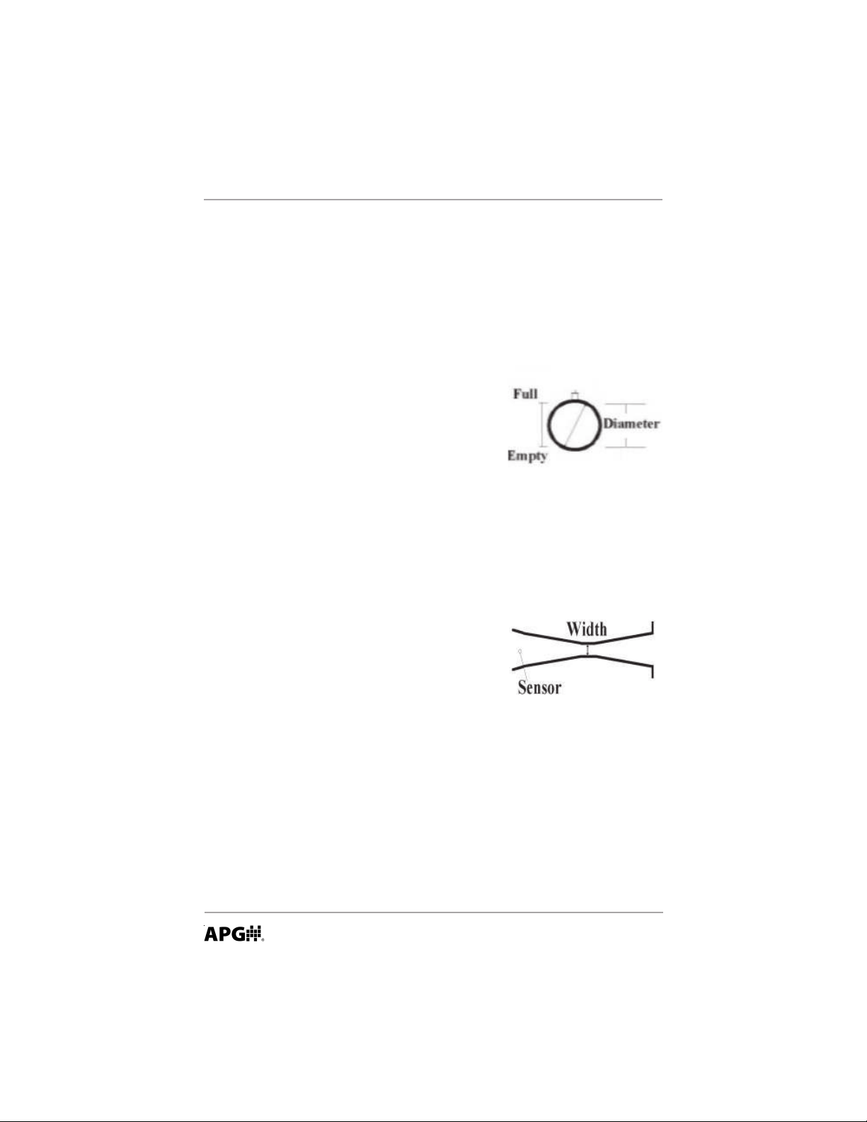
Volume Tank Type - Volume Mode (TankType)
Standing Cylindrical Tank with Hemispherical Bottom (SCTWHB)
Full Distance
0.00 – 25.00 ft
Default: 1.00 ft
Empty distance
1.00 – 25.00 ft
Default: 25.00 ft
T ank Diameter
0.00 – 100.00 ft
Radius of Hemisphere
0.00 – 100.00 ft
16
Standing Cylindrical Tank with Conical Bottom (SCTWCB)
Full Distance
0.00 – 25.00 ft
Default: 1.00 ft
Empty distance
1.00 – 25.00 ft
Default: 25.00 ft
T ank Diameter
0.00 – 100.00 ft
Automation Products Group, Inc.
APG...Providing tailored solutions for measurement applications
Tel: 1/888/525-7300 • Fax: 1/435/753-7490 • www.apgsensors.com • sales@apgsensors.com
Page 17

Rev. A3, 11/08 LPU-2428
Cone Diameter
0.00 – 100.00 ft
Cone Height
0.00 – 25.00 ft
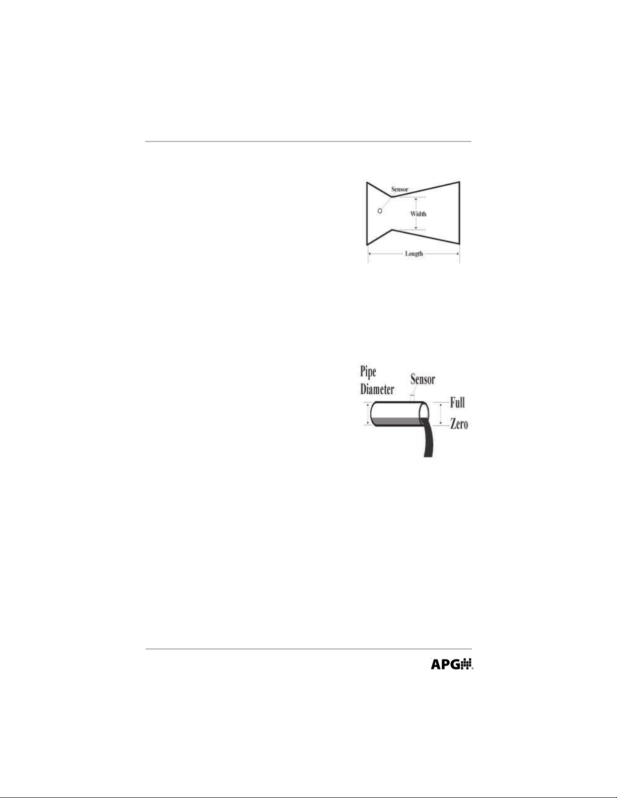
Standing Rectangular Tank with or without Chute (SRT)
Full Distance
0.00 – 25.00 ft
Default: 1.00 ft
Empty distance
1.00 – 25.00 ft
Default: 25.00 ft
Tank Length
0.00 – 100.00 ft
Tank Width
0.00 – 100.00 ft
Chute Length
0.00 – 25.00 ft
Chute Width
0.00 – 25.00 ft
Chute Height
0.00 – 25.00 ft
Horizontal Cylindrical Tank (HCT)
Full Distance
0.00 – 25.00 ft
Default: 1.00 ft
Empty distance
1.00 – 25.00 ft
Default: 25.00 ft
Tank Length
0.00 – 100.00 ft
Automation Products Group, Inc.
APG...Providing tailored solutions for measurement applications
Tel: 1/888/525-7300 • Fax: 1/435/753-7490 • www .apgsensors.com • sales@apgsensors.com
17
Page 18
LPU-2428 Rev. A3, 11/08
T ank Diameter
0.00 – 100.00 ft
Radius of Hemisphere
0.00 – 25.00 ft
Spherical Tank (ST)
Full Distance
0.00 – 25.00 ft
Default: 1.00 ft
Empty Distance
1.00 – 25.00 ft
Default: 25.00 ft
T ank Diameter
0.00 – 100.00 ft
Flow Type - Flume (FlowType)
Parshall (Parshall)
Max Flow
0.00 – 25.00 ft
Default: 1.00 ft
Zero Flow
1.00 – 25.00 ft
Default: 25.00 ft
Constant K
0.00 – 12000.00
Exponent n
0.00 – 2.00
Cutthroat (CutThroa)
18
Max Flow
0.00 – 25.00 ft
Default: 1.00 ft
Zero Flow
Automation Products Group, Inc.
APG...Providing tailored solutions for measurement applications
Tel: 1/888/525-7300 • Fax: 1/435/753-7490 • www.apgsensors.com • sales@apgsensors.com
Page 19
Rev. A3, 11/08 LPU-2428
1.00 – 25.00 ft
Default: 25.00 ft
Constant K
0.00 – 480.00
Exponent n1
0.00 – 2.00
Throat Width
0.00 – 25.00 ft
Exponent n2
0.00 – 2.00
Flow Type - Weir (Weir)
California Pipe (Californ)
Max Flow
1.00 – 25.00 ft
Default: 1.00 ft
Zero Flow
1.00 – 25.00 ft
Default: 25.00 ft
Constant K
0.00 – 1200.00
Exponent n1
0.00 – 2.00
Diameter of Pipe
0.00 – 25.00 ft
Exponent n2
0.00 – 3.00
Rectangular w/ constrictions (Rect w/c)
Max Flow
0.00 – 25.00 ft
Default: 1.00 ft
Automation Products Group, Inc.
APG...Providing tailored solutions for measurement applications
Tel: 1/888/525-7300 • Fax: 1/435/753-7490 • www .apgsensors.com • sales@apgsensors.com
19
Page 20

LPU-2428 Rev. A3, 11/08
Zero Flow
1.00 – 25.00 ft
Default: 25.00 ft
Constant K
0.00 – 420.00
Exponent n
0.00 – 2.00
Crest Length
0.00 – 25.00 ft
Rectangular w/o constrictions (Rect w/o)
Max Flow
0.00 – 25.00 ft
Default: 1.00 ft
Zero Flow
1.00 – 25.00 ft
Default: 25.00 ft
Constant K
0.00 – 420.00
Exponent n
0.00 – 2.00
Crest Length
0.00 – 25.00 ft
20
Trapezoidal (Trapazod)
Max Flow
0.00 – 25.00 ft
Default: 1.00 ft
Zero Flow
1.00 – 25.00 ft
Default: 25.00 ft
Constant K
Automation Products Group, Inc.
APG...Providing tailored solutions for measurement applications
Tel: 1/888/525-7300 • Fax: 1/435/753-7490 • www.apgsensors.com • sales@apgsensors.com
Page 21

Rev. A3, 11/08 LPU-2428
0.00 – 420.00
Exponent n
0.00 – 2.00
Crest Length
0.00 – 25.00 ft
Triangular or V-Notch (Triangul)
Max Flow
0.00 – 25.00 ft
Default: 1.00 ft
Zero Flow
1.00 – 25.00 ft
Default: 25.00 ft
Constant K
0.00 – 270.00
Exponent n
0.00 – 3.00
Equation (Equation)
Q=KHn (1)
Max Flow
0.00 – 25.00 ft
Default: 1.00 ft
Zero Flow
1.00 – 25.00 ft
Default: 25.00 ft
Constant K
0.00 – 10e308
Exponent n
0.00 – 10e308
Automation Products Group, Inc.
APG...Providing tailored solutions for measurement applications
Tel: 1/888/525-7300 • Fax: 1/435/753-7490 • www .apgsensors.com • sales@apgsensors.com
21
Page 22

LPU-2428 Rev. A3, 11/08
Q=KLHn (2)
Max Flow
0.00 – 25.00 ft
Default: 1.00 ft
Zero Flow
1.00 – 25.00 ft
Default: 25.00 ft
Constant K
0.00 – 10e308
Exponent n
0.00 – 10e308
Length
0.00 – 10e308
Q=K[L-XH]Hn (3)
Max Flow
0.00 – 25.00 ft
Default: 1.00 ft
Zero Flow
1.00 – 25.00 ft
Default: 25.00 ft
Constant K
0.00 – 10e308
Exponent n
0.00 – 10e308
Length
0.00 – 10e308
Constant X
0.00 – 10e308
Q=K[B-A/D]n1P
n2
(4)
22
Max Flow
0.00 – 25.00 ft
Default: 1.00 ft
Automation Products Group, Inc.
APG...Providing tailored solutions for measurement applications
Tel: 1/888/525-7300 • Fax: 1/435/753-7490 • www.apgsensors.com • sales@apgsensors.com
Page 23

Rev. A3, 11/08 LPU-2428
Zero Flow
1.00 – 25.00 ft
Default: 25.00 ft
Constant K
0.00 – 10e308
Exponent n1
0.00 – 10e308
Constant D
0.00 – 10e308
Exponent n2
0.00 – 10e308
Linearization Table (Only available through computer software)
Used for non-linear open channels and tanks. Linearization table holds
up to 32 entries.
Max Distance
0.00 – 25.00 ft
Default: 1.00 ft
Zero Distance
1.00 – 25.00 ft
Default: 25.00 ft
Automation Products Group, Inc.
APG...Providing tailored solutions for measurement applications
Tel: 1/888/525-7300 • Fax: 1/435/753-7490 • www .apgsensors.com • sales@apgsensors.com
23
Page 24

LPU-2428 Rev. A3, 11/08
Submersible (Submersi)
Used to directly replace a pressure transducer.
Submersible Range
0.00 – 25.00 ft
Default: 1.00 ft
Depth Distance: this parameter is used to limit the high end of
the analog output so that it will not go above a programmed
value. This setting becomes the output that is selected at the
20 mA distance. It can be used if it is desired for the sensor to
directly replace a pressure transducer.
1.00 – 25.00 ft
Default: 25.00 ft
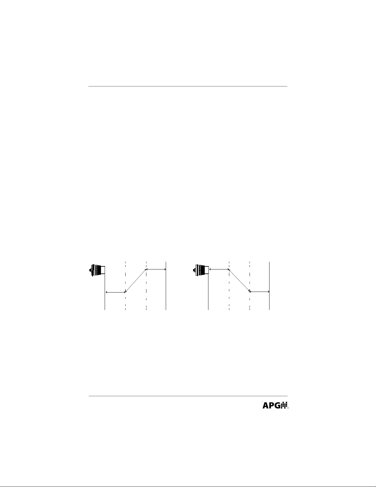
4-20 Setup (4-20 Set)
In Distance mode, the zero reference is from the face of the sensor. In
Level, Volume, or Flow modes, zero is referenced from the Zero
Distance, Empty Distance, or Zero Flow .
Minimum (Min) mA Setpoint (MinMaSet)
Sets the minimum mA distance, level, volume, or flow.
24
APG...Providing tailored solutions for measurement applications
Tel: 1/888/525-7300 • Fax: 1/435/753-7490 • www.apgsensors.com • sales@apgsensors.com
Automation Products Group, Inc.
Page 25
Rev. A3, 11/08 LPU-2428
Zero Point Max. Distance Zero Point Max. Distance
20 ma
4 ma
4 ma
20 ma
4ma
set point
20ma
Set Point
4ma
set point
20ma
Set Point
0.00 – 25.00 ft (Distance/Level)
Default: 1.00 ft
Maximum (Max) mA Setpoint (MaxMaSet)
Sets the maximum mA distance, level, volume, or flow.
0.00 – 25.00 ft (Distance/Level)
Default: 25.00 ft
Fail Safe (FailSafe)
Determines the output condition of the sensor in the event of a Loss of
Echo.
Hold, 3.8 mA, 22 mA
Default: Hold
Fail Safe Delay (FS Delay)
Sets the delay in seconds before the sensor will output a Fail Safe
condition.
15 – 9999 Seconds
Default: 15 Seconds
Calibration (Calibrat)
Min mA Value (MinMaVal)
Limits the low end of the mA output.
4.00 – Max mA Value
Default: 4.00
Automation Products Group, Inc.
APG...Providing tailored solutions for measurement applications
Tel: 1/888/525-7300 • Fax: 1/435/753-7490 • www .apgsensors.com • sales@apgsensors.com
25
Page 26

LPU-2428 Rev. A3, 11/08
Max mA Value (MaxMaVal)
Limits the high end of the mA output.
Min mA Value – 20.00
Default: 20.00
Min mA Trim (Min Trim)
Fine tunes the minimum mA current. For example, if the 4 mA on the
input device is reading 3.95 mA, increasing this parameter will increase
the minimum mA output.
0 – 999
Default: 500
Max mA Trim (Max Trim)
Fine tunes the maximum mA current. For example, if the 20 mA on the
input device is reading 20.15, decreasing this parameter will decrease
the maximum mA output.
0 – 999
Default: 500
Multiplier (Multipli)
Calibrates the sensor for variations in the speed of sound due to
irregular atmospheric conditions.
0 – 1.999
Default: 1.000
Offset (Offset)
Adjusts the zero reference at the sensor face.
-3.00 ft to +3.00 ft
Default: 0.00
Advanced (Advanced)
Temperature Compensation (TempComp)
Compensates for changes in the speed of sound due to temperature
changes. Note: if the internal temperature compensation is used, care
must be taken that the sensor is not exposed to direct sunlight. The
26
APG...Providing tailored solutions for measurement applications
Tel: 1/888/525-7300 • Fax: 1/435/753-7490 • www.apgsensors.com • sales@apgsensors.com
Automation Products Group, Inc.
Page 27

Rev. A3, 11/08 LPU-2428
radiant heat of the sun can heat the sensor above the ambient
temperature causing the sensor to over compensate for temperature
changes.
ON/OFF
Default: ON
Gain Control (GainCont)
Selects the gain control functions in the sensor.
Manual = user controls the Sensitivity & Pulses
AutoSense = sensor controls Sensitivity & Pulses
Hard Target = user controls the Sensitivity & Pulses
but the gain comes up slower
Soft Target = user controls the Sensitivity & Pulses
but the gain comes up faster
Default: AutoSense
Sensitivity (Sensitiv)
Sets the maximum level of gain that is applied to the echo. If Gain
Control is set to AutoSense, this parameter limits the maximum gain
used by the AutoSense feature.
0 to 100 %
Default: 100%
Pulses (Pulses)
Sets the number of pulses per transmit burst. If Gain Control is set to
AutoSense, this parameter limits the maximum pulses used by the
AutoSense feature. In acoustically active applications or small
enclosed areas, decreasing the number of pulses helps to reduce
multiple echoes.
0 – 16 pulses
Default: 16
Blanking (Blanking)
Sets a dead band distance in front of the sensor. Because of the
physical properties of an ultrasonic sensor, objects cannot be detected
approximately one foot from the face of the transducer. The Blanking
Automation Products Group, Inc.
APG...Providing tailored solutions for measurement applications
Tel: 1/888/525-7300 • Fax: 1/435/753-7490 • www .apgsensors.com • sales@apgsensors.com
27
Page 28

LPU-2428 Rev. A3, 11/08
can be extended and used to ignore unwanted targets close to the
sensor such as welds, seams, pipe fittings, and gaskets.
1.00 – 25.00 ft
Default: 1.00 ft
Utilities (Utilitie)
Simulation allows the user to input a simulated low level, high level and
the cycle time of the simulation. After these parameters are entered and
the simulation is activated the level reading will move linearly between
the programmed points at the specified interval.
Low Distance Simulation (LoDisSim)
1.00 – 25.00 ft
Default: 1.00
High Distance Simulation (HiDisSim)
1.00 – 25.00 ft
Default: 25.00
Simulation Cycle Time (SimCycle)
28
ON/OFF 0 – 9 seconds = OFF , 15 – 9999 = ON
Default = OFF
Reset (Reset)
Resets the sensor to factory defaults.
No Reset – Sensor Reset
Default: No Reset
File System (Only available through computer software)
Allows the user to save, load and edit text files that contain sensor
parameters.
Sensor to File
File to Sensor
Compare Sensor to File
Default: none
Automation Products Group, Inc.
APG...Providing tailored solutions for measurement applications
Tel: 1/888/525-7300 • Fax: 1/435/753-7490 • www.apgsensors.com • sales@apgsensors.com
Page 29

Rev. A3, 11/08 LPU-2428
Software Version (Version)
Displays the current software version running in the sensor.
Totalization (Totalize)
The sensor will have 2 flow totalizers. Totalization will update to
software in increments of one minute.
Non resetable totalizer
Resettable totalizer
Reset - Option to reset one totalizer
Programming Example:
Examples for each set of application (i.e., distance, level, volume, flow,
linearization table, and submersible) can be found by clicking the Instructions
button in the computer software. The following Volume application is taken
from these examples.
The LPU-2428 is mounted at the top of a 10 ft standing cylindrical tank with
diameter of 3 ft. The sensor needs to be setup to monitor volume in gallons
from 1 to 9 ft (remember sensor has a 1 foot blanking distance).
Automation Products Group, Inc.
APG...Providing tailored solutions for measurement applications
Tel: 1/888/525-7300 • Fax: 1/435/753-7490 • www .apgsensors.com • sales@apgsensors.com
29
Page 30

LPU-2428 Rev. A3, 11/08
Click Basic Setup.
Select Units to Feet.
Set Application to Volume.
Select Volume Units to Gallons.
Press Send to save (Wait until progress bar completes).
Click App. setup.
Set Tank Type to SCTWBH (Standing Cylindrical Tank with Hemispherical
Bottom).
Set Full Distance to 1 ft.
Set Empty Distance to 10 ft.
Set Tank Diameter to 3 ft. and set Radius of Hemi. to 0 ft.
30
Automation Products Group, Inc.
APG...Providing tailored solutions for measurement applications
Tel: 1/888/525-7300 • Fax: 1/435/753-7490 • www.apgsensors.com • sales@apgsensors.com
Page 31

Rev. A3, 11/08 LPU-2428
Click 4-20 setup.
Set Min Ma Set point (4mA). This value is usually set to zero.
Set Max Ma set point (20mA).
Press Send to save (wait until progress bar completes).
Automation Products Group, Inc.
APG...Providing tailored solutions for measurement applications
Tel: 1/888/525-7300 • Fax: 1/435/753-7490 • www .apgsensors.com • sales@apgsensors.com
31
Page 32

LPU-2428 Rev. A3, 11/08
Specifications - LPU-2428
Operating Range ............................. 1 ft. to 25 ft. (0.3 m - 7.62 m)
Supply Voltage ................................ 12 to 28 VDC
Output............................................. 4-20 mA (Max 600 ohms @ 24 VDC)
4-20 mA (Max 150 ohms @ 12 VDC)
(Includes barrier resistance)
Resolution ......................................0.1 in. (2.54 mm)
Accuracy ......................................... +/- 0.25% of range with no temp gradient
Sensor Adjustments .......................Interface through RST-4001
Maximum Current Draw .................. 4-20 mA (22 mA max in Fail Safe)
Transducer Type .............................Flat ceramic sealed PVDF face
Operating Temperature................... -40 to 60°C
Internal Temp. Compensation .......Yes
Sample Rate ....................................3 sec at 4 mA - 0.6 sec at 20 mA
Beam Pattern...................................9° off axis
Enclosure ........................................ NEMA 4X , IP65
Cable Connection ........................... 2 terminals
Approvals.......................................Class I, Div. 1, Groups C & D
Class I, Zone 0, AEx ia IIB, T3; IP65
Dimensions - in./mm
32
APG...Providing tailored solutions for measurement applications
Tel: 1/888/525-7300 • Fax: 1/435/753-7490 • www.apgsensors.com • sales@apgsensors.com
Automation Products Group, Inc.
Page 33

Rev. A3, 11/08 LPU-2428
Automation Products Group, Inc.
APG...Providing tailored solutions for measurement applications
Tel: 1/888/525-7300 • Fax: 1/435/753-7490 • www .apgsensors.com • sales@apgsensors.com
33
Page 34

LPU-2428 Rev. A3, 11/08
34
Automation Products Group, Inc.
APG...Providing tailored solutions for measurement applications
Tel: 1/888/525-7300 • Fax: 1/435/753-7490 • www.apgsensors.com • sales@apgsensors.com
Page 35

Rev. A3, 11/08 LPU-2428
Automation Products Group, Inc.
APG...Providing tailored solutions for measurement applications
Tel: 1/888/525-7300 • Fax: 1/435/753-7490 • www .apgsensors.com • sales@apgsensors.com
35
Page 36

AUTOMATION
APG...Providing tailored solutions
for measurement applications
Automation Products Group, Inc.
T el: 1/888/525-7300
Fax: 1/435/753-7490
e-mail: sales@apgsensors.com
www.apgsensors.com
GROUP, INC.
1/435/753-7300
PRODUCTS
Automation Products Group, Inc.
1025 W. 1700 N.
Logan, UT 84321
 Loading...