

Page 1

PRODUCTS
AUTOMATION
Operator’s Manual
GROUP, INC.
LPU-2127
Rev. A5, 1/14
APG...Providing tailored solutions for measurement applications
Tel: 1/888/525-7300 • Fax: 1/435/753-7490 • www.apgsensors.com • E-mail: sales@apgsensors.com
Automation Products Group, Inc.
Page 2

LPU-2127 Rev. A5, 1/14
Table of Contents
Warranty ......................................................................................... 3
Introducing...................................................................................... 4
Understanding Ultrasonics ............................................................. 5
Installation ...................................................................................... 7
Hazardous Mounting.................................................................... 8
Wiring.............................................................................................. 9
Programming ................................................................................ 10
Operation ................................................................................... 11
Calibration ................................................................................. 13
Utilities ...................................................................................... 14
Mode Sheet ................................................................................... 16
Specifications ................................................................................ 19
Certificate of Compliance ............................................................ 20
Automation Products Group, Inc.
2
APG...Providing tailored solutions for measurement applications
Tel: 1/888/525-7300 • Fax: 1/435/753-7490 • www.apgsensors.com • sales@apgsensors.com
Page 3

Rev. A5, 1/14 LPU-2127
• Warranty and Warranty Restrictions
APG warrants its products to be free from defects of material and workmanship
and will, without charge, replace or repair any equipment found defective upon
inspection at its factory, provided the equipment has been returned,
transportation prepaid, within 24 months from date of shipment from factory.
THE FOREGOING WARRANTY IS IN LIEU OF AND EXCLUDES ALL OTHER
WARRANTIES NOT EXPRESSLY SET FORTH HEREIN, WHETHER
EXPRESSED OR IMPLIED BY OPERATION OF LAW OR OTHERWISE
INCLUDING BUT NOT LIMITED TO ANY IMPLIED WARRANTIES OF
MERCHANTABILITY OR FITNESS FOR A PARTICULAR PURPOSE.
No representation or warranty, express or implied, made by any sales
representative, distributor, or other agent or representative of APG which is not
specifically set forth herein shall be binding upon APG. APG shall not be liable
for any incidental or consequential damages, losses or expenses directly or
indirectly arising from the sale, handling, improper application or use of the
goods or from any other cause relating thereto and APG’s liability hereunder, in
any case, is expressly limited to the repair or replacement (at APG’s option) of
goods.
Warranty is specifically at the factory. Any on site service will be provided at
the sole expense of the Purchaser at standard field service rates.
All associated equipment must be protected by properly rated electronic/
electrical protection devices. APG shall not be liable for any damage due to
improper engineering or installation by the purchaser or third parties. Proper
installation, operation and maintenance of the product becomes the
responsibility of the user upon receipt of the product.
Returns and allowances must be authorized by APG in advance. APG will
assign a Return Material Authorization (RMA) number which must appear on
all related papers and the outside of the shipping carton. All returns are subject
to the final review by APG. Returns are subject to restocking charges as
determined by APG’s “Credit Return Policy”.
Automation Products Group, Inc.
APG...Providing tailored solutions for measurement applications
Tel: 1/888/525-7300 • Fax: 1/435/753-7490 • www.apgsensors.com • sales@apgsensors.com
3
Page 4

LPU-2127 Rev. A5, 1/14
Introducing
The LPU series are loop-powered ultrasonic sensors. The LPU provides a
low-power non-contact level measurement solution. These units are provided
with 4-tactile switches and a 4-digit LCD display to provide the user feedback
in programming and sensor performance data.
Sensor features include:
• Loop powered for low power consumption.
• Built-in keypad and display for easy setup and distance readings.
• Rugged Kynar transducer housing for harsh environments and high degree
of chemical compatibility.
• Microprocessor-controlled.
• Listed by CSA for operation in Class 1 Division 2 Groups C & D and Class
1 Zone 2 A Ex nA IIB hazardous areas.
• NEMA 4X rating for outdoor applications.
Automation Products Group, Inc.
4
APG...Providing tailored solutions for measurement applications
Tel: 1/888/525-7300 • Fax: 1/435/753-7490 • www.apgsensors.com • sales@apgsensors.com
Page 5
Rev. A5, 1/14 LPU-2127
detection
area
beam spread
low sensitivity
and
pulses
high sensitivity
and
pulses
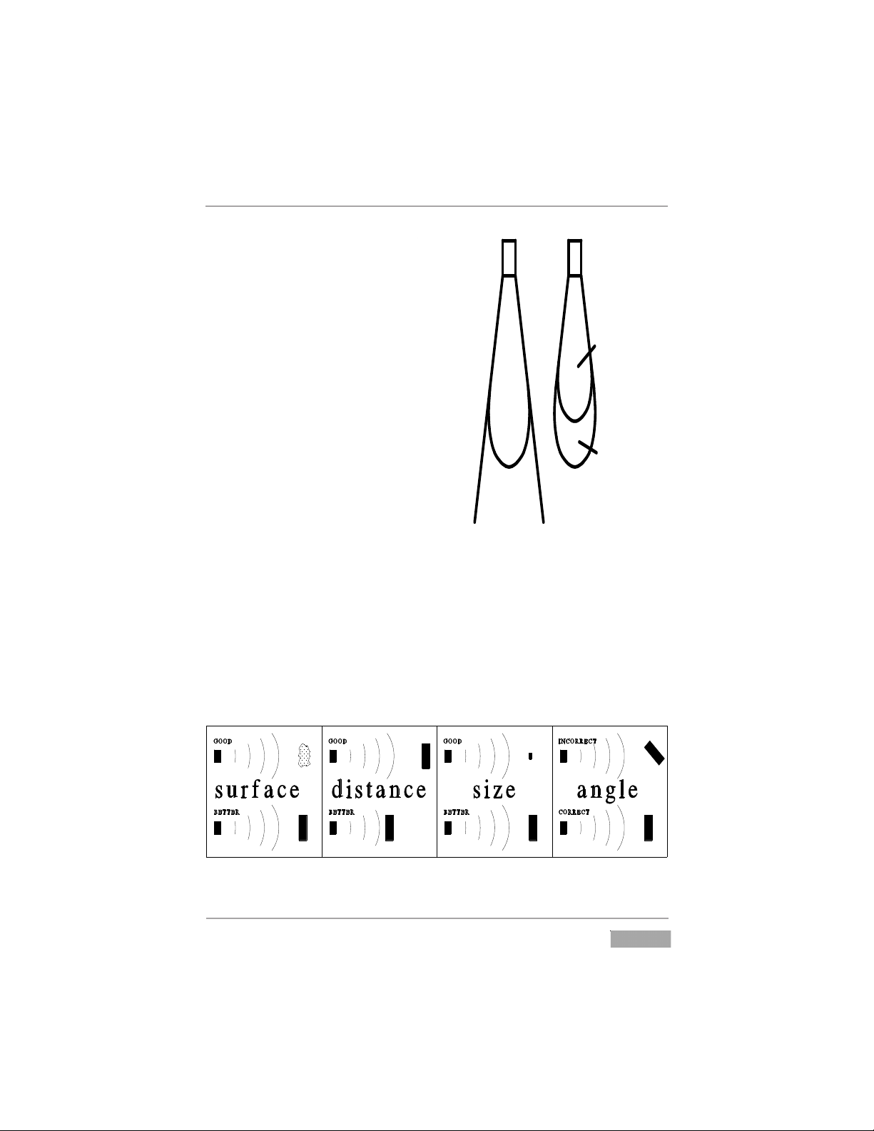
Understanding Ultrasonics
Ultrasonic sensors measure distance
using a transducer to send out
ultrasonic bursts. Each burst contains a
series of 1-20 pulsed sound waves that
emit in the shape of a cone, reflect off
the target, and are received by the
sensor. The time required for the sound
burst to travel to and from the target is
converted into a distance measurement
by the sensor.
Ultrasonic sensing is affected by
several factors including the target
surface, distance, size, and angle. The
following considerations will help
ensure the best possible target
conditions.
Surface
The ideal target surface is hard and smooth and perpendicular to the sensor.
This surface will reflect a greater amount of signal than a soft, sound wave
absorbent surface. A target with poor sound wave reflection characteristics will
reduce the operating distance of the sensor and decrease its accuracy.
APG...Providing tailored solutions for measurement applications
Tel: 1/888/525-7300 • Fax: 1/435/753-7490 • www.apgsensors.com • sales@apgsensors.com
Automation Products Group, Inc.
5
Page 6

LPU-2127 Rev. A5, 1/14
Distance
The shorter the distance from the sensor to an object, the stronger the
returning echo will be. Therefore, as the distance increases, the object requires
better reflective characteristics to return a sufficient echo.
Size
A large object will have a greater surface area to reflect the signal than a
small one, therefore, a large target will be detected at a greater distance than a
small target. The surface area recognized as the target is generally the portion
closest to the sensor.
Angle
The inclination of the object's surface facing the ultrasonic sensor affects the
reflectivity of the object. The portion perpendicular to the sensor returns the
echo. If the entire surface is at a great enough angle, the signal will be reflected
away from the sensor and no echo will be detected. Generally a target at an
angle greater than 5 degrees off perpendicular will not be detected.
Automation Products Group, Inc.
6
APG...Providing tailored solutions for measurement applications
Tel: 1/888/525-7300 • Fax: 1/435/753-7490 • www.apgsensors.com • sales@apgsensors.com
Page 7
Rev. A5, 1/14 LPU-2127
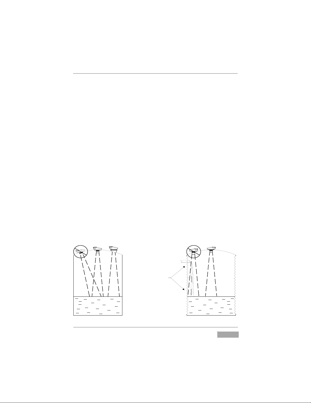
DO NOT mount the sensor
where the beam will intersect
objects such as fill streams,
pipes, ladder rungs, wall seams,
or corrugated tank walls.
Installation
The LPU sensor should be mounted so that it has a clear sound path to the
level monitored. Mount the sensor away from tank walls and inlets. The path
should be free from obstructions and as open as possible for the 9° off axis
beam pattern. Follow the guidelines mentioned in "Understanding
Ultrasonics", earlier in this manual. When using a stand pipe to mount the
sensor above the tank, the stand pipe should be seamless and no longer than 4
inches to provide a smooth path for the sound waves to propagate into the
tank. Seams from couplers, nipples or gaskets can cause erroneous echoes and
degrade the sensors performance. The LPU can be mounted in a coupler, or
flange using the 2” NPT threaded case.
Caution: Do not over tighten! The sensor should be threaded in only hand
tight.
The minimum detection range of the LPU is approximately 1 ft. The sensor
should be mounted to ensure the target does not come closer than the
minimum range or erroneous readings may result.
See the Hazardous Mounting section of this manual before mounting the
LPU sensor in a hazardous area.
APG...Providing tailored solutions for measurement applications
Tel: 1/888/525-7300 • Fax: 1/435/753-7490 • www.apgsensors.com • sales@apgsensors.com
Automation Products Group, Inc.
7
Page 8

LPU-2127 Rev. A5, 1/14
Automation Products Group, Inc.
APG...Providing tailored solutions for measurement applications
8
Tel: 1/888/525-7300 • Fax: 1/435/753-7490 • www.apgsensors.com • sales@apgsensors.com
Page 9
Rev. A5, 1/14 LPU-2127
4.25
Ammeter
COM
mA
Power Supply
(24Vdc)
+
-
4 to 20ma Out
+24vdc
Load Resistance
or Input Card
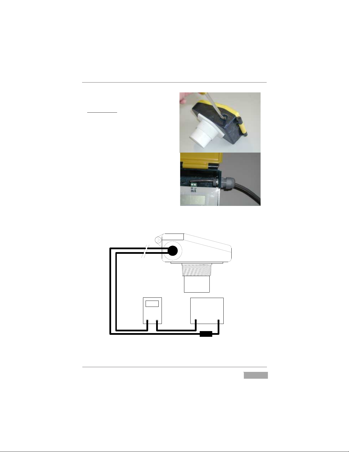
Wiring
Cable Entry
1. Remove the cable knock out with
lid closed.
2. Clear flashing.
3. Open lid.
4. Install cable gland or conduit
connection.
5. Connect cable as shown:
12 to 28 VDC to (+) Terminal
4 to 20 ma output to (-) Terminal
APG...Providing tailored solutions for measurement applications
Automation Products Group, Inc.
Tel: 1/888/525-7300 • Fax: 1/435/753-7490 • www.apgsensors.com • sales@apgsensors.com
9
Page 10

LPU-2127 Rev. A5, 1/14
Programming
The LPU is programmed using modes, similar to a digital wrist watch. The
LPU display and programming buttons can be accessed by loosening the screw
that secures and seals the sensor’s lid. The LCD display shows the distance
measurement. The display is also used to view the individual modes and their
values when programming.
The LPU has four programming buttons, MODE UP, MODE DOWN, VALUE
UP, and VALUE DOWN. The MODE UP/DN buttons allow the user to select
the desired mode while VALUE UP/DN buttons allow the user to view and alter
the settings.
To select a mode, press the MODE UP or MODE DOWN button until the
desired mode is displayed. Press the VALUE UP or VALUE DOWN button once
to view the current setting of that mode.
To change the selected mode setting, press the VALUE UP or VALUE DOWN
button until the desired value is displayed.
To STORE or SAVE the changed mode value, press the MODE UP or MODE
DOWN button once. At this point, the display will show the distance
measurement. The values are stored in a nonvolatile memory, and will not be
lost when power is turned off.
A list of the 17 modes is located on the LPU MODE SHEET near the end of
this manual.
10
Automation Products Group, Inc.
APG...Providing tailored solutions for measurement applications
Tel: 1/888/525-7300 • Fax: 1/435/753-7490 • www.apgsensors.com • sales@apgsensors.com
Page 11
Rev. A5, 1/14 LPU-2127
Zero Point Max. Distance Zero Point Max. Distancemode 11 mode 12 mode 11 mode 12
20 ma
4 ma
4 ma
20 ma
Operation
MODE DESCRIPTION PARAMETERS
1 Units Range = 0-2
Default = 0
0 = feet
1 = inches
2 = mm
Mode 1 is used to select the units of measurement that will be used
throughout the setup process and also for display. The units will also
determine the resolution of the display and the outputs. The resolution is: feet
0.01, inches 0.1 and millimeters 1.
NOTE: All modes must be set using the units selected in Mode 1.
MODE DESCRIPTION PARAMETERS
2 4 mA distance Units = Mode 1
Range = 0-9999
Default = 1.00 ft.
Mode 2 sets the 4 mA distance.
MODE DESCRIPTION PARAMETERS
3 20 mA distance Units = Mode 1
Range = 0-9999
Default = 25.00 ft.
Mode 3 sets the 20 mA distance.
APG...Providing tailored solutions for measurement applications
Tel: 1/888/525-7300 • Fax: 1/435/753-7490 • www.apgsensors.com • sales@apgsensors.com
Automation Products Group, Inc.
11
Page 12

LPU-2127 Rev. A5, 1/14
Operation (continued)
MODE DESCRIPTION PARAMETERS
4 Response Time Range = 1-3
Default = 1
1 = 3.3 ft/min (1m/min)
2 = 15ft/min (4.5m/min)
3 = >15 ft/min (4.5/min)
Mode 4 is used to select the desired response time. The response time
adjustment is the limit to which the LPU-2127 can keep up with different rates
of change. The response time parameter automatically sets internal filter
parameters for the programmed rate of change. More filter equates to a steadier
output. The most filter is used in setting 1, the least in setting 3.
MODE DESCRIPTION PARAMETERS
5 Fail-safe Range = 0 - 2
Default = 1
0 = hold last
1 = 22 mA
2 = 3.75 mA
Mode 5 sets the output condition that the sensor will revert to in the event of
a loss of echo condition. If this mode is set to 0, the sensor will hold the last
reading until the signal is regained. If set to 1, the output of the sensor will go
to 22 mA If set to 2, the output will go to 3.75 mA.
MODE DESCRIPTION PARAMETERS
6 Fail-safe Units = Seconds
Delay Range = 5-9999
Default = 15
Mode 6 sets the delay, in seconds, before the output will show a loss of echo
condition. When the LPU does not receive an echo, it will hold the last valid
condition for the number of seconds entered in Mode 5. When this time has
expired, the display and output will change to their fail-safe settings.
Most applications do not require the user to manipulate modes beyond 6.
Automation Products Group, Inc.
12
APG...Providing tailored solutions for measurement applications
Tel: 1/888/525-7300 • Fax: 1/435/753-7490 • www.apgsensors.com • sales@apgsensors.com
Page 13

Rev. A5, 1/14 LPU-2127
Calibration
MODE DESCRIPTION PARAMETERS
7 4 mA Trim Range = 0-9999
Default = 5000
Mode 7 fine tunes the minimum current sourced on the analog output.
MODE DESCRIPTION PARAMETERS
8 20 mA Trim Range = 0-9999
Default = 5000
Mode 8 fine tunes the maximum current sourced on the analog output.
MODE DESCRIPTION PARAMETERS
9 Calibration Range = 0-1999
Default = 1000
Mode 9 is used to calibrate the sensor for variations in the speed of sound
due to variations in atmospheres. The default of 1000 is used for most
applications. Assume a decimal after the first digit.
MODE DESCRIPTION PARAMETERS
10 Distance Offset Units = Mode 1
Range = -3.00 to 3.00
Default = 0
Mode 10 is used to change the zero point of the sensor.
APG...Providing tailored solutions for measurement applications
Automation Products Group, Inc.
Tel: 1/888/525-7300 • Fax: 1/435/753-7490 • www.apgsensors.com • sales@apgsensors.com
13
Page 14

LPU-2127 Rev. A5, 1/14
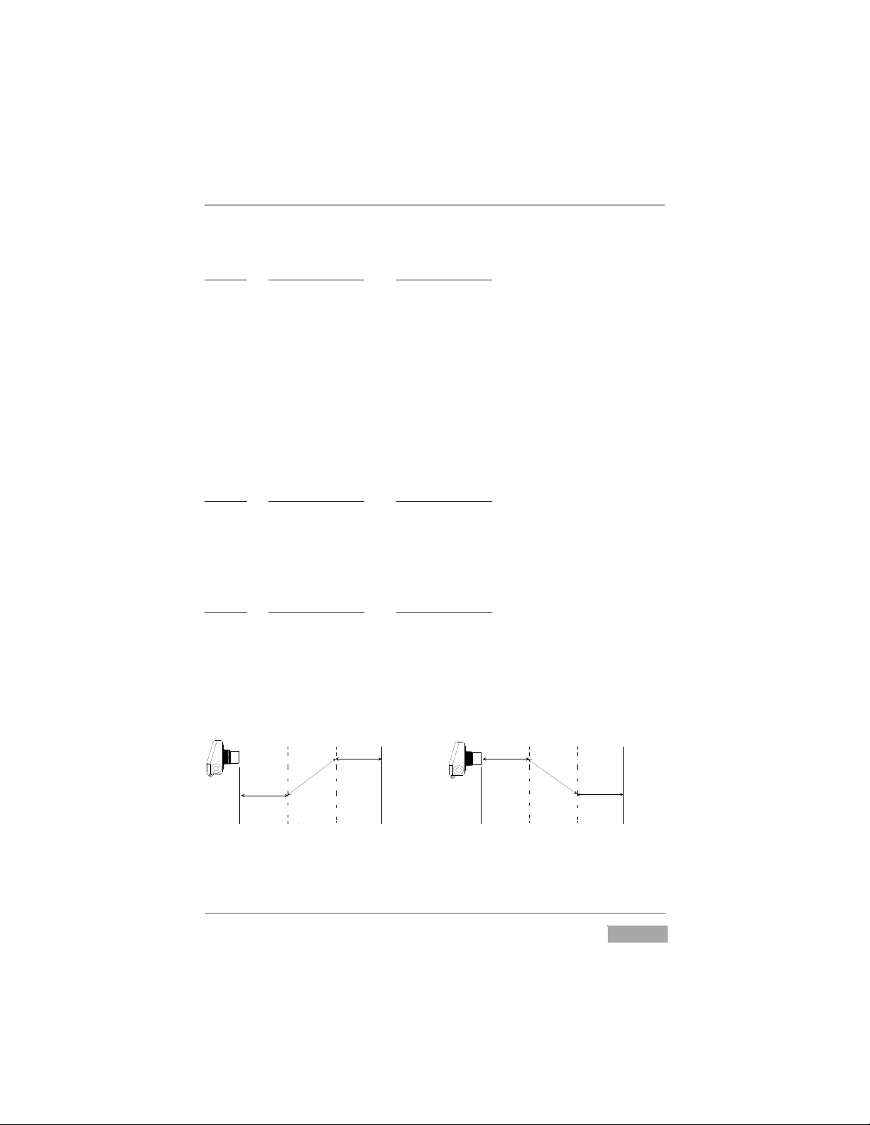
Step 1: Point the sensor at a target that is approximately at the
maximum measurement range. Adjust the Mul plier value so
that the sensor distance reading matches the actual measured
distance to the target.
Distance Calibra on
Use a wall or other large ß at target for calibra on at longer ranges.
Step 3: Repeat steps 1 and 2 un l the reading at each endpoint
matches the actual measured distance. The accuracy at both endpoint should improve with each repe on of steps 1 and 2.
measure
measure
Step 2: Point the sensor at a target that is approximately at the
minimum measurement range. Adjust the O! set value so that the
sensor distance reading matches the actual measured distance to
the target.
Automation Products Group, Inc.
14
APG...Providing tailored solutions for measurement applications
Tel: 1/888/525-7300 • Fax: 1/435/753-7490 • www.apgsensors.com • sales@apgsensors.com
Page 15

Rev. A5, 1/14 LPU-2127
Utilities
MODE DESCRIPTION PARAMETERS
11 Temperature Range = 0 - 2
Compensation Default = 1
0 = OFF
1 = ON
2 = View Temperature (degrees C)/ON
Mode 11 activates or deactivates the internal temperature compensation
circuit. The speed of sound changes with changes in temperature, therefore
changes in temperature can affect distance measurements. These affects can be
minimized by activating temperature compensation. If the mode is exited
while viewing temperature, temperature compensation is turned ON.
MODE DESCRIPTION PARAMETERS
12 AutoSense Range = 0 - 1
Default = 1
0 = Manual (user controls Sensitivity and Pulses)
1 = AutoSense (sensor controls Sensitivity and
Pulses)
Mode 12 activates or deactivates AutoSense. When operating with this
mode active, the LPU-2127 will automatically change the sensitivity and
pulses to match the application. Modes 13 and 15 limit the maximum level
that sensitivity and pulses can be manipulated when operating in AutoSense.
Modes 13 and 15 set the sensitivity and pulses when operating in manual
mode.
MODE DESCRIPTION PARAMETERS
13 Sensitivity Range = 0 - 100%
Default = 100%
Mode 13 sets the level of gain that is applied to the echo. When operating in
AutoSense, this parameter limits the gain that can be applied to the echo. If
operating in manual, this parameter sets the receive gain. When in manual
mode, set the sensitivity to the minimum value that will allow the target to be
reliably tracked through the full range of environmental conditions.
Automation Products Group, Inc.
APG...Providing tailored solutions for measurement applications
Tel: 1/888/525-7300 • Fax: 1/435/753-7490 • www.apgsensors.com • sales@apgsensors.com
15
Page 16

LPU-2127 Rev. A5, 1/14
Utilities (Continued)
MODE DESCRIPTION PARAMETERS
14 Blanking Units = Determined by Mode 1
Range = 0.5 -16 ft.
Default = 1.00 ft.
Mode 14 sets the blanking distance. The blanking distance is the zone from
the sensor to a point where the first echo will be accepted. Because of the
physical properties of an ultrasonic sensor, objects cannot be detected closer
than approximately 1 foot from the face of the transducer. This distance varies
according to how much energy is being transmitted (Mode 5) and the
installation. Low pulses and soft mounting may allow target detection as close
as 6 inches. The blanking distance can also be used to ignore unwanted targets
close to the sensor such as welds, seams, pipe fittings, or gaskets.
MODE DESCRIPTION PARAMETERS
15 Pulses Range = 1-20
Default = 16
Mode 15 sets the maximum number of pulses the sensor can transmit when
operating in AutoSense or simply the number of pulses when operating in
manual (Mode 12). The LPU emits a burst of pulses and measures the time it
takes for the burst to travel to and from the target. The more pulses that are
sent in a burst, the stronger the returning echo. When operating in manual
mode, increase the strength of the transmission by increasing the number of
pulses for detecting soft targets in damping environments. In acoustically
active environments or small enclosed areas, decrease the number of pulses to
decrease the energy transmitted and reduce multiple echoes.
MODE DESCRIPTION
16 Software Version
Mode 16 displays the software version of the LPU.
MODE DESCRIPTION
17 Reset
Mode 17 resets the LPU to factory default settings
Automation Products Group, Inc.
16
APG...Providing tailored solutions for measurement applications
Tel: 1/888/525-7300 • Fax: 1/435/753-7490 • www.apgsensors.com • sales@apgsensors.com
Page 17

Rev. A5, 1/14 LPU-2127
Mode Sheet
MODE DESCRIPTION PARAMETERS EXPLANATION
1 Units Range = 0 - 2
0 - feet
1- inches
2 - mm
Default = 0
2 4mASet Point Units = Mode 1
Range = 0 - 9999
Default = 1.00
3 20mA Set Point Units = Mode 1
Range = 0 - 9999
Default = 25.00
4 Response Time Range = 1-3
Default = 1
1 = 3.3 ft/min (1m/min)
2 = 15ft/min (4.5m/min)
3 = >15 ft/min (4.5/min)
5 Fail-Safe Range = 0 - 2
Default = 0
0 = Hold last reading
1 = 22ma
2 = 3.75ma
6 Fail-Safe Units = seconds
Delay Range=5-9999
Default = 15
Sets the units to be displayed and
used in setup. NOTE: Set Mode 1
before any other modes.
Sets the end point for the 4 mA
analog limit.
Sets the end point for the 20 mA
analog limit.
Sets the reaction rate of the sensor.
Sets the output status in the event
of a loss of echo condition.
Sets the delay in seconds before
the output will show a loss of echo
condition.
7 4mA Trim Range = 0 - 9999
Default = 5000
8 20mA Trim Range = 0 - 9999
Default = 5000
9 Calibration Range = 0000 - 1999
Default = 1000
Automation Products Group, Inc.
APG...Providing tailored solutions for measurement applications
Tel: 1/888/525-7300 • Fax: 1/435/753-7490 • www.apgsensors.com • sales@apgsensors.com
Fine tunes the 4 mA analog
output.
Fine tunes the 20 mA analog
output.
Sets the calibration factor.
Assume a decimal after first digit.
17
Page 18

LPU-2127 Rev. A5, 1/14
Mode Sheet (continued)
MODE DESCRIPTION PARAMETERS EXPLANATION
10 Offset Distance Range =-999 - +999
Default = 0
11 Temperature Range = 0 - 2
Compensation Default = 1
0 = OFF
1 = ON
2 = View/ON
12 Autosense Range = 0 - 1
Default = 1
0 = OFF
1 = ON
13 Sensitivity Range = 0 - 100%
Default = 100
14 Blanking Units = Mode 1
Range = 0.5 to 16 ft.
Default = 1.00
15 Pulses Units = Pulses
Range = 1 - 20
Default = 16
16 Software
Version
Sets an offset for the display.
Activates or deactivates internal
Temperature Compensation.
Activates or deactivates AutoSense.
Sets to top sensitivity level. Zero is
the lowest sensitivity settomg and
100 is the highest.
Sets a dead zone in front of the
transducer where echoes are
ignored.
Sets the number of ultrasonic
pulses transmitted in each burst. 20
being the strongest transmit setting.
Displays the Software Version
17 Reset Range = 0 - 1
Default = 0
Automation Products Group, Inc.
18
APG...Providing tailored solutions for measurement applications
Tel: 1/888/525-7300 • Fax: 1/435/753-7490 • www.apgsensors.com • sales@apgsensors.com
Resets the mode parameters to their
default values. Entering a 1 will
reset the parameters.
Page 19

Rev. A5, 1/14 LPU-2127
Signal Strenth Indicator
Bars located on the left side of the LCD display indicate the strength of the return signal
from the sensor.
Excellent
Good
Fair
Loss of Echo
Automation Products Group, Inc.
APG...Providing tailored solutions for measurement applications
Tel: 1/888/525-7300 • Fax: 1/435/753-7490 • www.apgsensors.com • sales@apgsensors.com
19
Page 20

LPU-2127 Rev. A5, 1/14
5.500"
6.050"
2.000"
4.000"
2.400"
2.300"
2" NPT
Specifications — LPU-2127
Operating Range ............................ 1 ft. to 25 ft. (0.3 m - 7.62 m)
Supply Voltage ............................... 12 to 28 VDC
Output ............................................. 4-20 mA (Max 600 ohms @ 24 VDC)
4-20 mA (Max 150 ohms @ 12 VDC)
(Includes barrier resistance)
Resolution ...................................... 0.1 in. (2.54 mm)
Accuracy .........................................+/- 0.25% of range with no temp gradient
Sensor Adjustments ........................Programmable modes
Maximum Current Draw ................ 22 mA max
Transducer Type .............................Flat ceramic sealed PVDF face
Operating Temperature................... -40 to 60°C
Internal Temp. Compensation ....... Yes
Sample Rate ................................... 3 seconds at 4ma - 0.6seconds at 20 ma
Beam Pattern .................................. 9° off axis
Enclosure........................................ NEMA 4X , IP65
Cable Connection .......................... 2 terminals
Dimensions
20
Automation Products Group, Inc.
APG...Providing tailored solutions for measurement applications
Tel: 1/888/525-7300 • Fax: 1/435/753-7490 • www.apgsensors.com • sales@apgsensors.com
Page 21
Rev. A5, 1/14 LPU-2127
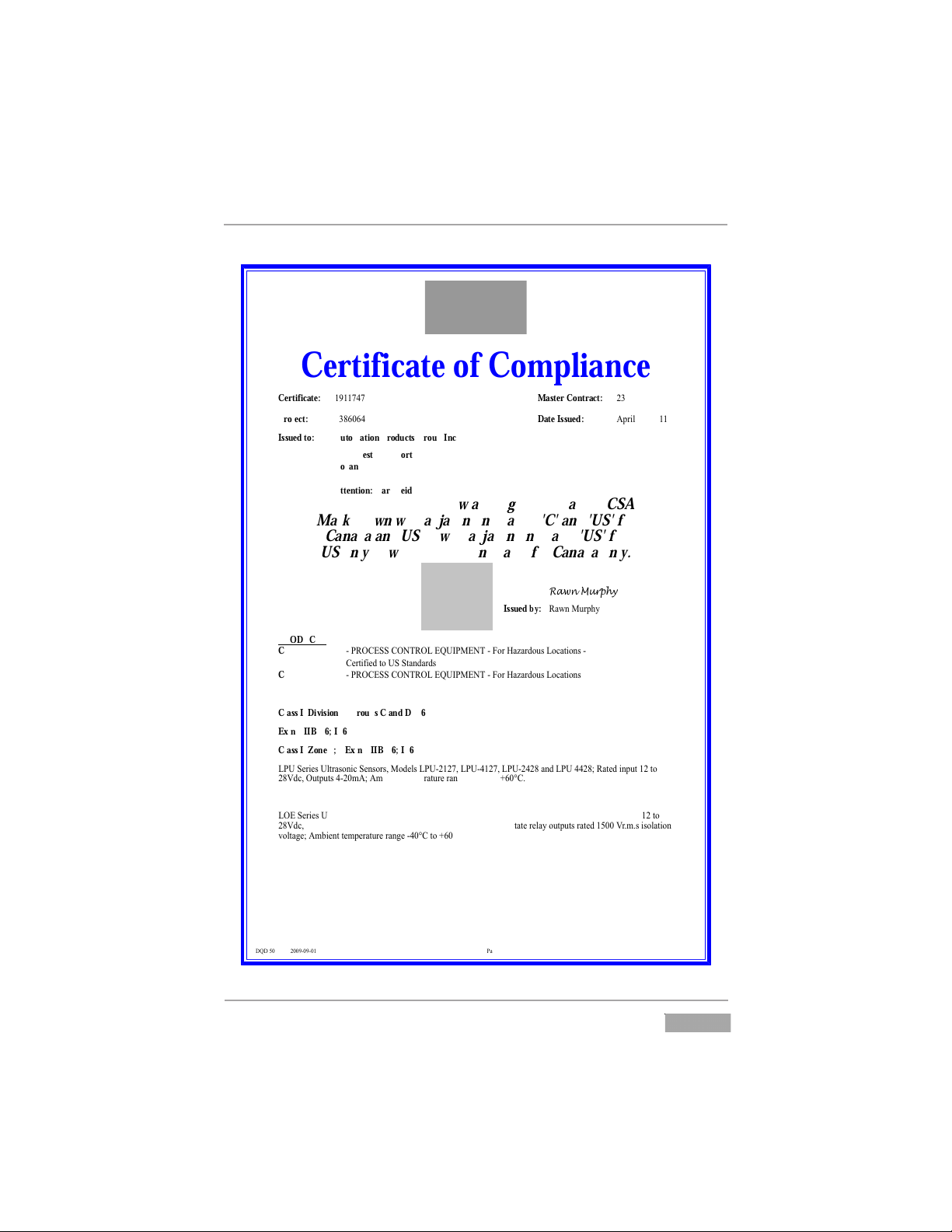
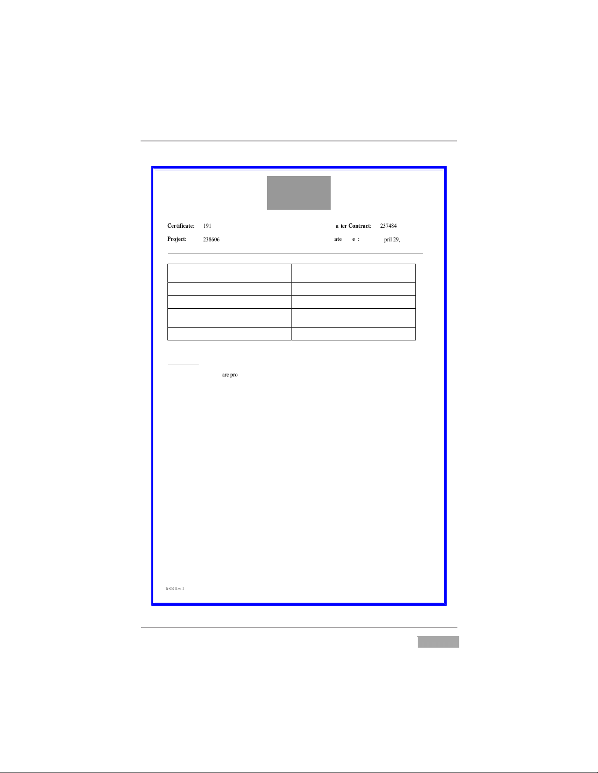
Certificate of Compliance
Certificate:
! "#"
Master Contract:
$%"#&#
Project:
$%&'('#
Date Issued:
)*+,-.$!/.$(
010.2(".3456.$((!7(!7( 89:4;.
Issued to: Automation Products Group Inc
1025 West 1700 North
Logan, UT 84321
USA
Attention: Karl Reid
The products listed below are eligible to bear the CSA
Mark shown with adjacent indicators 'C' and 'US' for
Canada and US or with adjacent indicator 'US' for
US only or without either indicator for Canada only.
!"#$%&'()*
Issued by:
39<=.>?+*@A
PRODUCTS
CLASS 2258 82
7.83BCDEE.CBFG3BH.D1IJ8>DFG.7.KL+.M9N9+OL?P.HLQ9R,L=P.7
C4+R,S,4O.RL.IE.ER9=O9+OP
CLASS 2258 02
7.83BCDEE.CBFG3BH.D1IJ8>DFG.7.KL+.M9N9+OL?P.HLQ9R,L=P
.
Class I, Division 2, Groups C and D, T6
Ex nA IIB T6; IP65
Class I, Zone 2; AEx nA IIB T6; IP65
H8I.E4+,4P.I-R+9PL=,Q.E4=PL+P/.>LO4-P.H8I7$ $"/.H8I7# $"/.H8I7$#$&.9=O.H8I.##$&T.39R4O.,=*?R. $.RL
$&UOQ/.B?R*?RP.#7$(V)T.)VW,4=R.R4V*4+9R?+4.+9=:4.7#(XC.RL.Y'(XC6.
.
HBD.E4+,4P.I-R+9PL=,Q.E4=PL+P/.>LO4-P.HBD7$ $'/.HBD7' $'/.9=O.HBD7% %'T.39R4O.,=*?R.#&U0C.L+. $.RL
$&UOQ/.$((.V).QL=R9,=,=:.R<L.L*R,Q9--A7QL?*-4O.>BEKDG.PL-,O7PR9R4.+4-9A.L?R*?RP.+9R4O. 2((.U+6V6P.,PL-9R,L=
5L-R9:4T.)VW,4=R.R4V*4+9R?+4.+9=:4.7#(XC.RL.Y'(XC6
FLR4;
Z.G@4.HBD.E4+,4P.P@9--.W4.*L<4+4O.WA.9.P?,R9W-4.Q4+R,S,4O.C-9PP.$.*L<4+.P?**-A6
Automation Products Group, Inc.
APG...Providing tailored solutions for measurement applications
Tel: 1/888/525-7300 • Fax: 1/435/753-7490 • www.apgsensors.com • sales@apgsensors.com
21
Page 22

LPU-2127 Rev. A5, 1/14
Certificate:
! "#"
Master Contract:
$%"#&#
Project:
$%&'('#
Date Issued:
)*+,-.$!/.$(
010.2(".3456.$((!7(!7( 89:4;.$
.
CLASS 2258 04 - PROCESS CONTROL EQUIPMENT - Intrinsically Safe, Entity - For Hazardous
Locations
CLASS 2258 84 - PROCESS CONTROL EQUIPMENT - Intrinsically Safe, Entity - For Hazardous
Locations - Certified to US Standards
Class I, Division 1, Groups C and D, T3
Ex ia IIB, T3 (Canada); IP65
Class I, Zone 0; AEx ia IIB, T3 (USA); IP65
<8=7$#$&.9>?.<8=7##$&.@-A+9BC>,D.B4>BC+BE.39A4?.,>*@A. $.AC.$&F0G/.H@A*@AB.#7$(I)/.)IJ,4>A.A4I*4+9A@+4
+9>:4.7#(KG.AC.L'(KG6..M>A,AN.89+9I4A4+B.FI9O.P.$&F0G/.QI9O.P. %(I)/.8,6.(6! R/.G,.P.(>S/.<,.P. (TU/
,>A+,>B,D9--N.B9V4.WX4>.DC>>4DA4?.,>.9DDC+?9>D4.W,AX.Q>BA9--9A,C>.?+9W,>:.!(($"#"6
.
.
.
APPLICABLE REQUIREMENTS
.
.
.G)YZG[).[A9>?9+?.G$$6$.YC6.(7\! ]4>4+9-.34^@,+4I4>AB.7.G9>9?,9>.M-4DA+,D9-.GC?4/.89+A
QQ
.G[).[A9>?9+?.G$$6$.YC6 #$7\ !&" 8+CD4BB.GC>A+C-.M^@,*I4>A.Q>?@BA+,9-.8+C?@DAB
.G)YZG[).[A9>?9+?.G$$6$.YC6 2"7!$ Q>A+,>B,D9--N.[9V4.9>?.YC>7Q>D4>?,54.M^@,*I4>A.VC+
=B4.,>.U9_9+?C@B.<CD9A,C>B
.G)YZG[).[A9>?9+?.G$$6$.YC6$ %7\ !&" YC>7,>D4>?,54.M-4DA+,D9-.M^@,*I4>A.VC+.=B4.,>.G-9BB.Q/
0,5,B,C>.$.U9_9+?C@B.<CD9A,C>B.Q>?@BA+,9-.8+C?@DAB
.G)YZG[).[A9>?9+?.M'(("!7(7($ M-4DA+,D9-.)**9+9A@B.VC+.MO*-CB,54.]9B.)AICB*X4+4B.`
89+A.(;.]4>4+9-.34^@,+4I4>AB
.G)YZG[).[A9>?9+?.M'(("!7 7($ M-4DA+,D9-.)**9+9A@B.VC+.MO*-CB,54.]9B.)AICB*X4+4B.`
89+A. ;.Q>A+,>B,D.[9V4AN.a,a
.G)YZG[).[A9>?9+?.M'(("!7 27($ M-4DA+,D9-.)**9+9A@B.VC+.MO*-CB,54.]9B.)AICB*X4+4B.7
89+A. 2;.bN*4.CV.8+CA4DA,C>.a>a
.G)YZG[).[A9>?9+?.G$$6$.YC6.'(2$!7(2 04:+44B.CV.8+CA4DA,C>.8+C5,?4?.JN.M>D-CB@+4B.cQ8
GC?4d
.=<.[A9>?9+?.2(& Q>?@BA+,9-.GC>A+C-.M^@,*I4>A
.=<.[A9>?9+?.! % Q>A+,>B,D9--N.[9V4.)**9+9A@B.9>?.)BBCD,9A4?.)**9+9A@B
VC+.=B4.,>.G-9BB.Q/.QQ/.9>?.QQQ/.0,5,B,C>. /.U9_9+?C@B
cG-9BB,V,4?d.<CD9A,C>B
22
Automation Products Group, Inc.
APG...Providing tailored solutions for measurement applications
Tel: 1/888/525-7300 • Fax: 1/435/753-7490 • www.apgsensors.com • sales@apgsensors.com
Page 23
Rev. A5, 1/14 LPU-2127
Certificate:
! "#"
Master Contract:
$%"#&#
Project:
$%&'('#
Date Issued:
)*+,-.$!/.$(
010.2(".3456.$((!7(!7( 89:4;.%
.)<=>?>=).=@9AB9+B. $6 $6( 7$((" <CA,AD4AB,54.E-4D@+,D9-.EFG,*H4A@.IC+.JK4.,A.L-9KK
>.9AB.>>/.0,5,K,CA.$/.9AB.L-9KK.>>>.0,5,K,CAK. .9AB.$
M9N9+BCGK.OL-9KK,I,4BP.QCD9@,CAK
.JQ.=@9AB9+B.'(("!7( E-4D@+,D9-.)**9+9@GK.IC+.ER*-CK,54.S9K.)@HCK*T4+4K.U
89+@.(;.S4A4+9-.34FG,+4H4A@K
JQ.=@9AB9+B.'(("!7 E-4D@+,D9-.)**9+9@GK.IC+.ER*-CK,54.S9K.)@HCK*T4+4K
89+@. ;.>A@+,AK,D.=9I4@V.W,W
JQ.=@9AB9+B.'(("!7 2 E-4D@+,D9-.)**9+9@GK.IC+.ER*-CK,54.S9K.)@HCK*T4+4K
89+@. 2;.E-4D@+,D9-.)**9+9@GK.X,@T.YV*4.CI.8+C@4D@,CA
WAW
>EL.'(2$! 04:+44K.CI.8+C@4D@,CA.8+C5,B4B.ZV.EAD-CKG+4K.O>8
LCB4P
..
MARKINGS
YT4.IC--CX,A:.H9+[,A:K.9+4.*+C5,B4B.CA.L=)7)DD4*@4B.OL-9KK."!$$7( /.\,-4.AGHZ4+.!!% 'P.9BT4K,54.-9Z4K@CD[.8+CBGD@.<GHZ4+."&" .H9AGI9D@G+4B.ZV.%].LCH*9AV/.XT,DT.,K.KG,@9Z-4.IC+.,ABCC+.C+.CG@BCC+.GK4.CA
8-9K@,D.S+CG*.^>>/.9@.9.H9R,HGH.K4+5,D4.@4H*4+9@G+4.CI.&(_L.C+.T,:T4+6..YT4.-9Z4-.K@CD[.KT9--.Z4.*+,A@4B.X,@T
CA4.CI.@T4.9**+C54B.*+,A@4+.9AB.,A[.DCHZ,A9@,CAK.9K.K*4D,I,4B.,A.@T4.H9AGI9D@G+4+K.-,K@,A:.9AB.@T4.I,A,KT4B.-9Z4,K.9II,R4B.@C.@T4.TCGK,A:6
` ]9AGI9D@G+4+aK.A9H4/.b)G@CH9@,CA.8+CBGD@K.S+CG*c/.C+.L=).]9K@4+.LCA@+9D@.<GHZ4+.b$%"#&#c/.9Bd9D4A@
@C.@T4.L=).]9+[.,A.-,4G.CI.]9AGI9D@G+4+aK.A9H46
` ]CB4-.AGHZ4+;.9K.K*4D,I,4B.,A.@T4.83e0JLY=.K4D@,CA/.9ZC546
` E-4D@+,D9-.+9@,A:K;.9K.K*4D,I,4B.,A.@T4.83e0JLY=.K4D@,CA/.9ZC546
` )HZ,4A@.@4H*4+9@G+4.+9@,A:;.9K.K*4D,I,4B.,A.@T4.83e0JLY=.K4D@,CA/.9ZC54.OH9V.Z4.9ZZ+45,9@4BP6
` ]9AGI9D@G+,A:.B9@4.,A.]]ff.IC+H9@/.C+.K4+,9-.AGHZ4+/.@+9D49Z-4.@C.HCA@T.CI.H9AGI9D@G+46
` YT4.L=).]9+[.X,@T.bLc.9AB.bJ=c.,AB,D9@C+K/.9K.KTCXA.CA.@T4.L4+@,I,D9@4.CI.LCAIC+H,@V6
` M9N9+BCGK.QCD9@,CA.B4K,:A9@,CA;.9K.K*4D,I,4B.,A.@T4.83e0JLY=.K4D@,CA/.9ZC546
` Y4H*4+9@G+4.LCB4;.9K.K*4D,I,4B.,A.@T4.83e0JLY=.K4D@,CA/.9ZC54.O]9V.9**49+.CA.DCA@+C-.B+9X,A:P6
` L-9KK.>.0,5,K,CA. .9BB,@,CA9-.]9+[,A:K.7
` bER,9c.IC--CX4B.ZV.b>>gc
` b><Y3><=>L)QQf.=)\Ec
` bh)3<><SU.Ei8Qe=>e<.M)j)30.U.=Jg=Y>YJY>e<.e\.Le]8e<E<Y=.])f.>]8)>3
><Y3><=>L.=)\EYfc.OEFG,59-4A@.XC+B,A:.,K.9DD4*@9Z-4P6
` bh)3<><SU.Ye.83E^E<Y.>S<>Y>e<.e\.\Q)]])gQE.e3.Le]gJ=Y>gQE.)Y]e=8ME3E=/
0>=Le<<EY.8ehE3.gE\e3E.=E3^>L><Sc6
` b>AK@9--.*4+.0+9X,A:.!(($"#&c.OC+.4FG,59-4A@P;.9K.K*4D,I,4B.,A.@T4.83e0JLY=.K4D@,CA/.9ZC54
` L-9KK.>.0,5,K,CA.$.9BB,@,CA9-.]9+[,A:K.U
` bER.A)c.IC--CX4B.ZV.b>>gc
` bh)3<><SU.0e.<eY.0>=Le<<ELY.E1J>8]E<Y.J<QE==.)3E).>=.k<eh.Ye.gE.<e<7
M)j)30eJ=c6
` bh)3<><S.U.8eYE<Y>)Q.EQELY3e=Y)Y>L.LM)3S><S.M)j)30.U.=EE.><=Y3JLY>e<=c.OC+
4FG,59-4A@P6
APG...Providing tailored solutions for measurement applications
Automation Products Group, Inc.
Tel: 1/888/525-7300 • Fax: 1/435/753-7490 • www.apgsensors.com • sales@apgsensors.com
23
Page 24

LPU-2127 Rev. A5, 1/14
Certificate:
! "#"
Master Contract:
$%"#&#
Project:
$%&'('#
Date Issued:
)*+,-.$!/.$(
010.2(".3456.$((!7(!7( 89:4;.#
< =>+.?@4.A8B.C4+,4D.B-?+9D>E,F.C4ED>+D/.?@4.G>+HD.I34J4+4EF4.,ED?9--9?,>E.H+9G,E:.EKLM4+.!(($"#2N.O>+
4PK,59-4E?Q;.9D.D*4F,J,4H.,E.?@4.83R0BSTC.D4F?,>E/.9M>54
< =>+.?@4.ARU.C4+,4D.B-?+9D>E,F.C4ED>+D/.?@4.G>+HD.I34J4+4EF4.,ED?9--9?,>E.H+9G,E:.EKLM4+.!((%#'!N.O>+
4PK,59-4E?Q;.9D.D*4F,J,4H.,E.?@4.83R0BSTC.D4F?,>E/.9M>54
< =>+.?@4.ARU.C4+,4D.B-?+9D>E,F.C4ED>+D/.?@4.L9EK9-.D@9--.F>E?9,E.?@4.J>-->G,E:.G>+HD;..IV)3WXWY.Z
WRWSRW0BSTX[U.CB3=)SU.R=.T\U.\RBCXWY.])^._U.S\)3YU0._^.WRWSRW0BSTX[U
]U0X)/.SAU)W.VXT\.).0)]8.SART\N
Note - Jurisdictions in Canada may require these markings to also be provided in French language. It is the
responsibility of the manufacturer to provide bilingual marking, where applicable, in accordance with the
requirements of the Provincial Regulatory Authorities. It is the responsibility of the manufacturer to determine
this requirement and have bilingual wording added to the "Markings".
Automation Products Group, Inc.
APG...Providing tailored solutions for measurement applications
24
Tel: 1/888/525-7300 • Fax: 1/435/753-7490 • www.apgsensors.com • sales@apgsensors.com
Page 25
Rev. A5, 1/14 LPU-2127
APG...Providing tailored solutions for measurement applications
Automation Products Group, Inc.
Tel: 1/888/525-7300 • Fax: 1/435/753-7490 • www.apgsensors.com • sales@apgsensors.com
25
Page 26

LPU-2127 Rev. A5, 1/14
26
Automation Products Group, Inc.
APG...Providing tailored solutions for measurement applications
Tel: 1/888/525-7300 • Fax: 1/435/753-7490 • www.apgsensors.com • sales@apgsensors.com
Page 27

PRODUCTS
AUTOMATION
Operator’s Manual
GROUP, INC.
APG...Providing tailored solutions for measurement applications
Tel: 1/888/525-7300 • Fax: 1/435/753-7490 • www.apgsensors.com • E-mail: sales@apgsensors.com
Automation Products Group, Inc.
 Loading...