

Page 1

AUT OMATION
Operator’s Manual
PRODUCTS
GROUP, INC.
LOE-2126
LOE-3136
LOE-6126
Internet Enabled Ultrasonic Sensor
Rev. B, 1/12
Automation Products Group, Inc.
APG...Providing tailored solutions for measurement applications
Tel: 1/888/525-7300 • Fax: 1/435/753-7490 • www.apgsensors.com • E-mail: sales@apgsensors.com
Page 2

LOE Series Rev. B, 1/12
Table of Contents
Warranty......................................................................................... 3
Understanding Ultrasonics .......................................................... 4-5
Installa on ...................................................................................... 6
Powering the LOE ........................................................................... 7
Extended Network .......................................................................... 8
Sensor Setup (DHCP) ...................................................................... 9
Accessing the Internal Web Pages .................................................. 9
Network Se ngs .......................................................................... 10
Basic Parameters ..................................................................... 11-14
Trip Point Control .................................................................... 15-18
Confi guring Website Alarms ...................................................... 18
Applica on Parameters ........................................................... 19-24
Modbus Se ngs ...................................................................... 25-26
Using Level and Flow Website ................................................. 27-33
Se ng Website Alarms ........................................................ 28-31
Sensor Rest .............................................................................. 32-33
Specifi ca ons ................................................................................ 34
Dimensions ................................................................................... 35
Automation Products Group, Inc.
APG...Providing tailored solutions for measurement applications
2
Tel: 1/888/525-7300 • Fax: 1/435/753-7490 • www.apgsensors.com • sales@apgsensors.com
Page 3

Rev. B, 1/12 LOE Series
Warranty and Warranty Restric ons
APG warrants its products to be free from defects of material and workmanship
and will, without charge, replace or repair any equipment found defec ve
upon inspec on at its factory, provided the equipment has been returned,
transporta on prepaid, within 24 months from date of shipment from factory.
THE FOREGOING WARRANTY IS IN LIEU OF AND EXCLUDES ALL OTHER
WARRANTIES NOT EXPRESSLY SET FORTH HEREIN, WHETHER EXPRESSED OR
IMPLIED BY OPERATION OF LAW OR OTHERWISE INCLUDING BUT NOT LIMITED
TO ANY IMPLIED WARRANTIES OF
MERCHANTABILITY OR FITNESS FOR A PARTICULAR PURPOSE.
No representa on or warranty, express or implied, made by any sales
representa ve, distributor, or other agent or representa ve of APG which is
not specifi cally set forth herein shall be binding upon APG. APG shall not be
liable for any incidental or consequen al damages, losses or expenses directly
or indirectly arising from the sale, handling, improper applica on or use of the
goods or from any other cause rela ng thereto and APG’s liability hereunder, in
any case, is expressly limited to the repair or replacement (at APG’s op on) of
goods.
Warranty is specifi cally at the factory. Any on site service will be provided at
the sole expense of the Purchaser at standard fi eld service rates.
All associated equipment must be protected by properly rated electronic/
electrical protec on devices. APG shall not be liable for any damage due
to improper engineering or installa on by the purchaser or third par es.
Proper installa on, opera on and maintenance of the product becomes the
responsibility of the user upon receipt of the product.
Returns and allowances must be authorized by APG in advance. APG will
assign a Return Material Authoriza on (RMA) number which must appear
on all related papers and the outside of the shipping carton. All returns are
subject to the fi nal review by APG. Returns are subject to restocking charges as
determined by APG’s “Credit Return Policy”.
Automation Products Group, Inc.
APG...Providing tailored solutions for measurement applications
Tel: 1/888/525-7300 • Fax: 1/435/753-7490 • www.apgsensors.com • sales@apgsensors.com
3
Page 4
LOE Series Rev. B, 1/12
• Understanding Ultrasonics
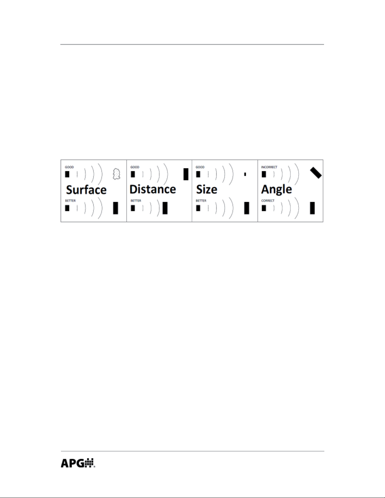
Ultrasonic sensors use a transducer to transmit bursts of ultrasonic sound
waves. Each burst contains a series of pulsed sound waves that emit in the
shape of a cone, refl ect off the target, and are detected by the sensor. The me
required for the sound waves to travel to and from the target is converted into
a distance measurement by the sensor. Ultrasonic sensing is aff ected by several
factors including the target surface, distance, size, and angle. The following
considera ons will help ensure the best possible target condi ons.
Surface
The ideal target surface is hard and smooth. This type of surface will refl ect a
greater amount of signal than a so or uneven surface. Sound wave absorbent
materials, such as granules and powders, will reduce the opera ng range of the
sensor and decrease measurement accuracy.
Distance
Sound wave a enua on increases as the distance traveled increases.
Therefore, targets at longer ranges require be er refl ec ve characteris cs than
targets that are closer to the sensor.
Size
A large object will have a greater surface area to refl ect the signal than a
smaller one. Therefore, a large target will be detected at a greater distance
than a small target. The surface area recognized as the target will generally be
the por on closest to the sensor.
Automation Products Group, Inc.
APG...Providing tailored solutions for measurement applications
4
Tel: 1/888/525-7300 • Fax: 1/435/753-7490 • www.apgsensors.com • sales@apgsensors.com
Page 5
Rev. B, 1/12 LOE Series
Angle
The inclina on of the object’s surface in rela on to the sensor face will aff ect
the strength of the refl ected sound waves. Surfaces perpendicular to the
sensor will refl ect more signal directly back to the sensor. If a surface is more
than a few degrees off perpendicular, enough of the signal will be refl ected
away from the sensor that the target will not be detected. Generally speaking,
a target angle greater than 5 degrees off perpendicular will not be detected.
The target angle becomes increasingly cri cal as the distance to the target
increases.
Environmental Condi ons
Temperature, humidity, vapors, dust, and pressure can aff ect the sensor’s
performance. APG ultrasonic sensors are designed to compensate for many of
these condi ons. However, if the condi ons are extreme, sensor performance
can be degraded enough to require the use of a longer-range sensor than
normal condi ons would require. Ultrasonic sensors may not be suitable for
applica ons with heavy chemical vapors (such as solvents or gasoline), heavy
dust or when signifi cant surface foam is present.
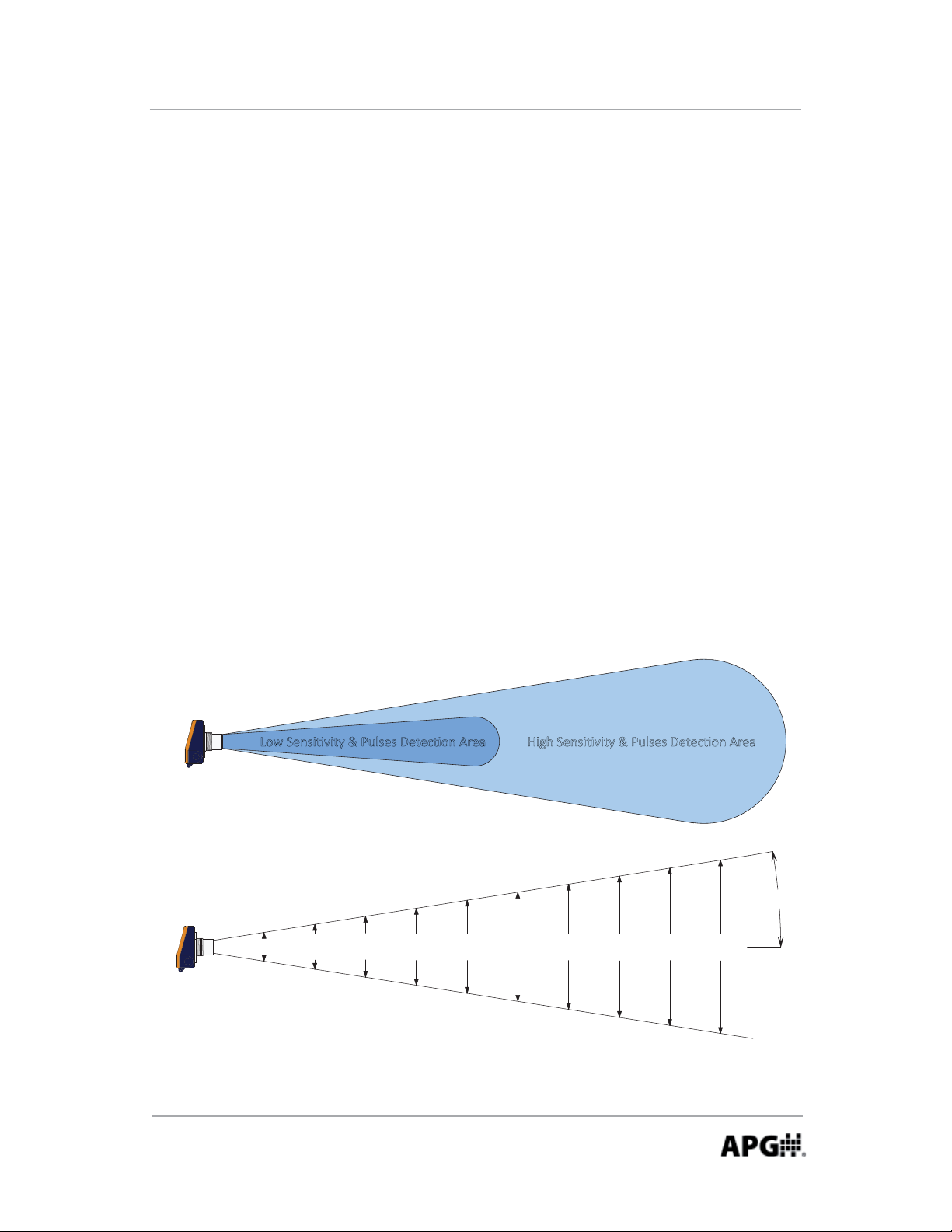
>Žǁ^ĞŶƐŝƟǀŝƚLJΘWƵůƐĞƐĞƚĞĐƟŽŶƌĞĂ ,ŝŐŚ^ĞŶƐŝƟǀŝƚLJΘWƵůƐĞƐĞƚĞĐƟŽŶƌĞĂ
.
8
f
f
7
t
f
t
.
6
f
t
.
5
.
4
f
t
.
f
3
2
f
f
t.
1
3
.
8
in
e
a
m
a
l
b
c
y
p
i
T
t.
in
7
.
6
.
e
a
d
s
p
r
t
.
in
1
1
.4
.
n
o
f
a
.
2
.
in
1
5
a
tr
u
l
1
9
s
e
n
ic
s
o
.
.
in
8
in
2
2
p
e
s
o
o
r
n
.
in
.6
.
2
6
g
a
a
t
in
r
t
.
3
m
t
3
4
n
.
i
0
.
4
m
u
im
a
x
Automation Products Group, Inc.
APG...Providing tailored solutions for measurement applications
Tel: 1/888/525-7300 • Fax: 1/435/753-7490 • www.apgsensors.com • sales@apgsensors.com
t
.
1
0
f
t
.
9
.
2
in
s
e
f
9
°
.
.
3
8
in
t
g
.
in
s
e
t
it
iv
y
n
s
it
5
Page 6
LOE Series Rev. B, 1/12
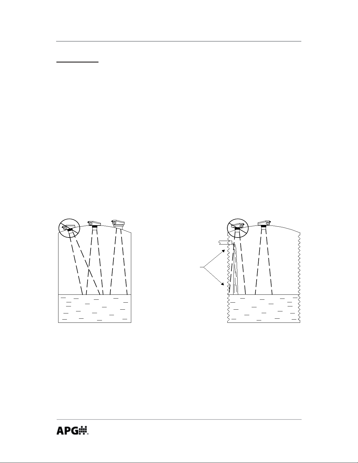
DO NOT mount the sensor
where the beam will intersect
objects such as fill streams,
pipes, ladder rungs, wall seams,
or corrugated tank walls.
Installa on
The LOE must be mounted in a loca on with an unobstructed column of air to
the target. The beam-spread chart on the previous page can be used as a rough
guide to determine the required diameter of the air column for ranges of 10
feet or less. A 3 to 4 foot diameter air column is typically suffi cient even at the
maximum range of the sensor.
The sensor should be mounted to ensure the target does not come closer than
the minimum sensing range (blanking distance).
The sensor should be mounted so that the sensor face is perpendicular to the
target surface. Even just a few degrees off -perpendicular can cause a loss of
echo condi on. Proper alignment becomes increasingly important as the range
to the target increases.
Stand Pipe Moun ng
When using a stand pipe to raise the sensor above a tank, use a single seamless
piece of pipe to provide the sound waves a smooth path to propagate into the
tank. Because the sound waves becomes concentrated along the pipe walls,
even small sharp edges, such as seams or burs, can cause errant readings.
6
Automation Products Group, Inc.
APG...Providing tailored solutions for measurement applications
Tel: 1/888/525-7300 • Fax: 1/435/753-7490 • www.apgsensors.com • sales@apgsensors.com
Page 7
Rev. B, 1/12 LOE Series
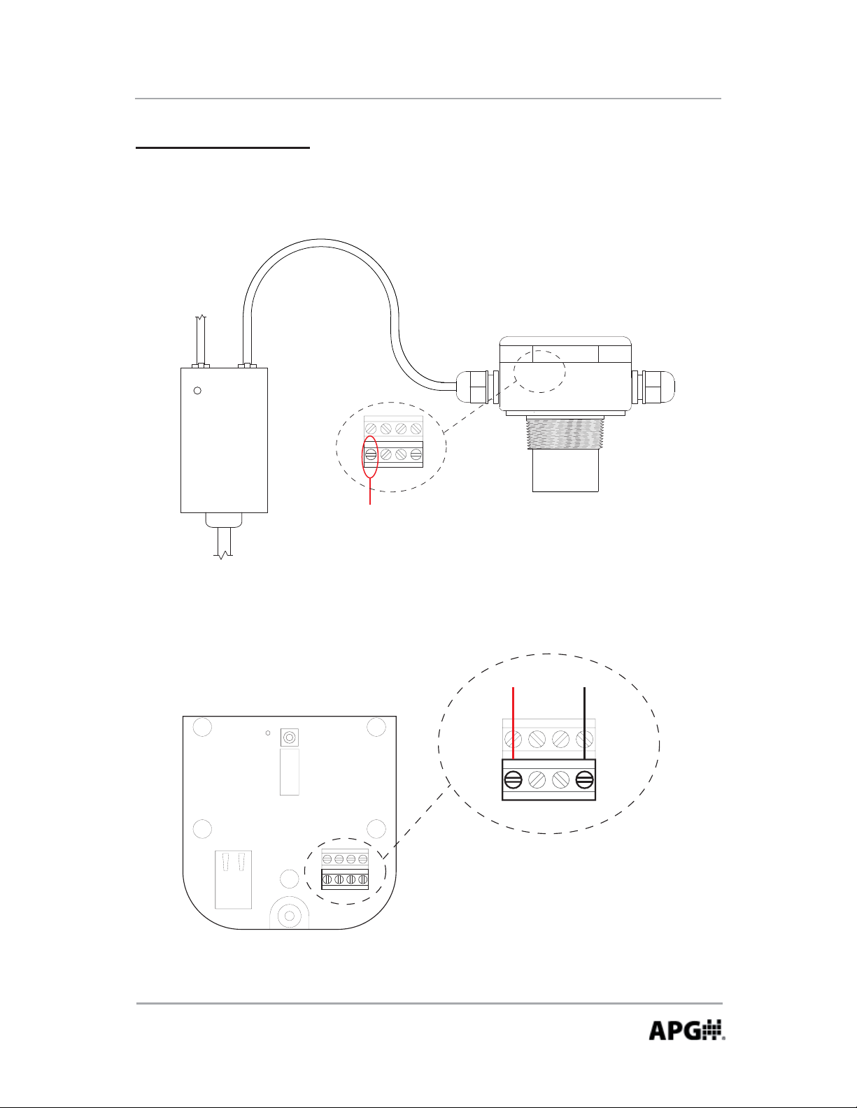
Powering the LOE
The LOE can be powered using a 48 V POE connec on or a standard 12-28 Vdc
power supply.
POE Wiring
To
Network
Connection
LAN + DCLAN
POWER
POE
Power
Injector
24V BAGND
RS-485
To A C
power
12-28 Vdc Power Supply Wiring
COM
OK
SEND/
RESET
24V B A GND
RS-485
Terminal inside housing
supplies 24 Vdc to power
attached Modbus devices
when powering the LOE
from a POE source.
To 12-28 Vdc Power Supply
+
24V BAGND
RS-485
-
Automation Products Group, Inc.
APG...Providing tailored solutions for measurement applications
Tel: 1/888/525-7300 • Fax: 1/435/753-7490 • www.apgsensors.com • sales@apgsensors.com
7
Page 8
LOE Series Rev. B, 1/12
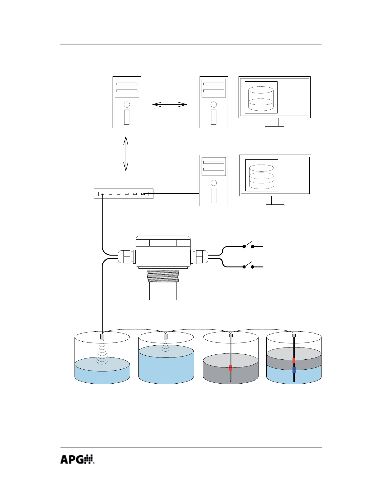
Extended Network
Server Hosting
Website and
Logged Data
Connection
to
Internet
Network / Internet Connection
Computer
on
Internet
Computer
on
Local
Network
Solid State Relays
Modbus Input
8
MNU Ultrasonic Sensors MP Magnetostrictive Float Level Sensors
Automation Products Group, Inc.
APG...Providing tailored solutions for measurement applications
Tel: 1/888/525-7300 • Fax: 1/435/753-7490 • www.apgsensors.com • sales@apgsensors.com
Page 9
Rev. B, 1/12 LOE Series
Sensor Setup via DHCP (automa c IP confi gura on)
Connect the LOE to a network that provides access to the internet, and apply
power to the sensor. The COM LED should begin to fl ash once every 30
seconds, indica ng the DHCP is a emp ng to establish communica on with the
web site. Once communica on is established, the COM LED will illuminated.
NOTE: see Troubleshoo ng DHCP if COM LED con nues to fl ash from more than
2-3 minutes.
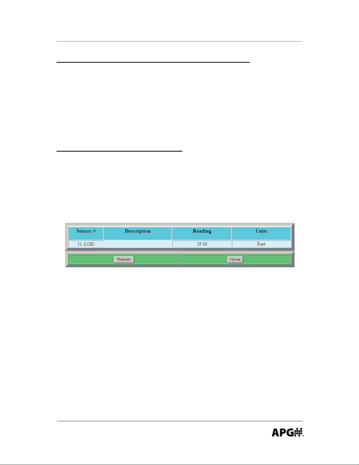
Accessing the Internal Web Pages
To access the sensor’s se ngs, open an Internet browser, and in the address
bar enter: loe_# where # is the sensor’s serial number beginning at the
fi rst whole number. For example if the serial number is L000001275, then
you would enter loe_1275 into the browser address bar. The following screen
should appear:
NOTE: if typing the loe_# does not work, it may indicate the DHCP has saved
a previous name for the IP assigned. Power down the sensor and have the
System Administrator delete this name from the DHCP server.
Next, click the “Home” bu on and use the following default login when
prompted:
Username: admin Password: password
NOTE: use the Security link on the main page to set the desired Username
and Password.
Automation Products Group, Inc.
APG...Providing tailored solutions for measurement applications
Tel: 1/888/525-7300 • Fax: 1/435/753-7490 • www.apgsensors.com • sales@apgsensors.com
9
Page 10
LOE Series Rev. B, 1/12
Chick the “Home” bu on again to enter the main page. The sensor parameters
are described in the ensuing pages.
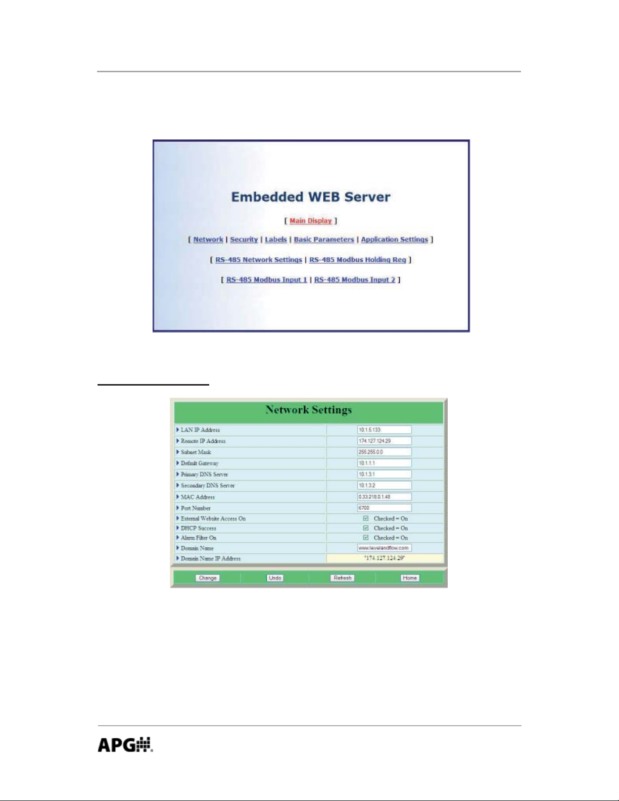
Network Se ngs
The Network Se ngs are provided for advanced users only and shouldn’t nor-
mally require changes. The LOE comes defaulted with DHCP enabled, meaning
the sensor only requires access to internet and it will automa cally connect to
the www.levelandfl ow.com website and confi gure its own Network Se ngs.
NOTE: refer to page
APG...Providing tailored solutions for measurement applications
10
Tel: 1/888/525-7300 • Fax: 1/435/753-7490 • www.apgsensors.com • sales@apgsensors.com
18 for a descrip on of the Alarm Filter func on.
Automation Products Group, Inc.
Page 11
Rev. B, 1/12 LOE Series
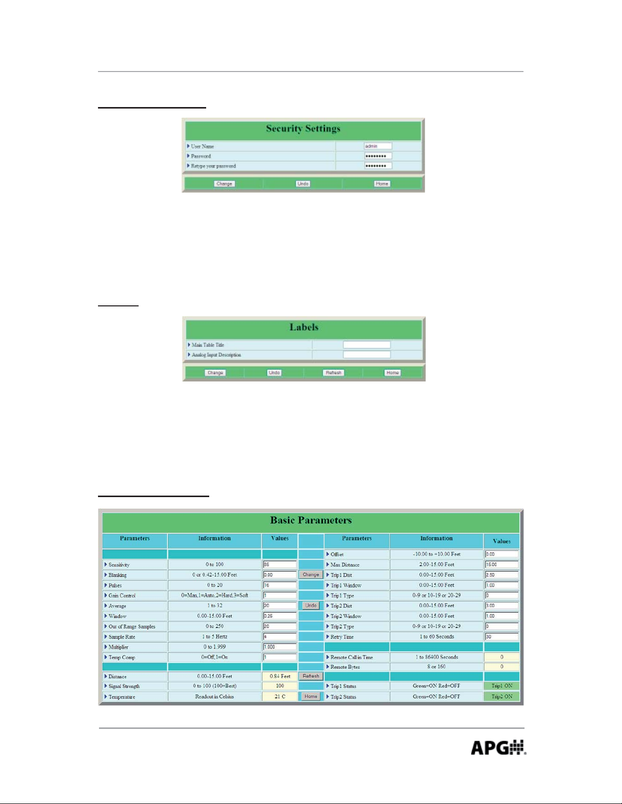
Security Se ngs
The Security Se ngs allow the user to set the username and password required
to access the sensor se ngs. The default Username is admin and the Password
is password.
Labels
Allows the user to assign custom labels to the Main Display. Labels apply only
to the internal webpage--labels on the www.levelandfl ow.com website must be
set through the website.
Basic Parameters
Automation Products Group, Inc.
APG...Providing tailored solutions for measurement applications
Tel: 1/888/525-7300 • Fax: 1/435/753-7490 • www.apgsensors.com • sales@apgsensors.com
11
Page 12

LOE Series Rev. B, 1/12
Basic Parameters (con nued)
Sensi vity
Controls the level of amplifi ca on applied to the target signal. The sensi vity
se ng is expressed as a percentage; 0 to 100%. When opera ng in Autosense
mode, the Sensi vity se ng acts as an upper limit constraint (see Gain Control
for details).
Blanking
Sets the distance, beginning at the sensor face, to the point where the sensor
will begin looking for target signals. All targets closer than the blanking distance
will be ignored. The blanking should never be set to less than the minimum
range specifi ca on of the sensor. If the target enters the blanking area, errant
readings will occur.
NOTE: the LOE-6126 has the ability to track a target to as close as 1” from
the sensor face. This feature is limited to targets that will remain perfectly
perpendicular to the sensor face.
Control to 1 (Autosense) and then se ng the Blanking to 0.
This feature is enabled by se ng the Gain
Pulses
Controls the number of sound wave pulses being sent in each ultrasonic
burst. The greater the number of pulses, the stronger the transmi ed signal.
When opera ng in Autosense mode, the Pulses se ng acts as an upper limit
constraint (see Gain Control for details).
Gain Control (0, 1, 2, 3)
Determines the method in which gain is applied to returning target signals. In
Manual mode, the Sensi vity and Pules se ngs are applied as a sta c values.
In Autosense Mode, the sensor self-adjusts the Pulses and Sensi vity levels
(within the bounds of their respec ve se ngs) in order to op mize the signal
strength.
0 = Manual Mode (sta c Sensi vity & Pulses values)
1 = Autosense (auto-adjus ng Sensi vity & Pulses values)
2 = Hard-Target (increases gain slowly as distance increases)
3 = So -Target (increases gain quickly as distance increase)
12
Automation Products Group, Inc.
APG...Providing tailored solutions for measurement applications
Tel: 1/888/525-7300 • Fax: 1/435/753-7490 • www.apgsensors.com • sales@apgsensors.com
Page 13

Rev. B, 1/12 LOE Series
Basic Parameters (con nued)
Averaging
Defi nes the number of target readings that will be averaged together. Each
qualifi ed sample (see Filter Window and Out of Range Samples below) is placed
into a fi rst-in, fi rst-out (FIFO) buff er and averaged with previous samples to gen-
erate a steady output. A higher Averaging se ng will result in smoother read-
ings, but will also result in slower the response me to rapid target changes.
Window
Sets the width of the target acceptance window. The target acceptance
window is a zone, centered around the current target reading, within which
any target detected will be considered legi mate and fi gured into the averaging
buff er. Any target detected outside of the Window will be considered “out of
range” and will be ignored based on the se ng in the Out of Range Samples
parameter (see below). The Filter Window extends both direc ons, both closer
than and further away from, the current target reading. For example, if the
sensor is detec ng a target at 5 . and the Filter Window is set at 1 ., then any
target detected between 4 . and 6 . will be accepted.
Out of Range Samples
Determines the number of consecu ve target readings that must fall outside
of the acceptance window before the “out of range” target is recognized and
included in the averaging buff er. For example, suppose the Out Of Range
Samples is set to 10. If a target is suddenly detected outside of the acceptance
window, it will be ignored un l it has been detected for 10 consecu ve samples,
at which point it will be qualifi ed as a legi mate target. If the “out of range”
target was detected for only 9 consecu ve samples before moving out of the
sensing area, it would never be acknowledged as a target and the reading
would stay with the last qualifi ed target sample.
Sample Rate
Sets the interval between target readings. Op ons allow rates from once per
second (1 Hz) to 5 mes per second (5 Hz). It is highly recommended that the
Sample Rate be set only as fast as is necessary for the applica on.
Automation Products Group, Inc.
APG...Providing tailored solutions for measurement applications
Tel: 1/888/525-7300 • Fax: 1/435/753-7490 • www.apgsensors.com • sales@apgsensors.com
13
Page 14

LOE Series Rev. B, 1/12
Basic Parameters (con nued)
Mul plier
Sets the conversion Mul plier that will be applied to the sensor readings. The
default is 1.000 (see note below) and typically does not need to be adjusted.
However, since the speed of sound is not constant through all environments,
the mul plier parameter allows the user to adjust for varia ons in atmosphere
when maximum accuracy is required.
Temperature Compensa on (0 = Off , 1 = On)
Used to enable or disable the internal temperature compensa on of the sen-
sor. Enabling the internal temperature compensa on can reduce the eff ects of
temperature changes by 50% or more, depending on the temperature gradient
through the sensing range.
Off set
Used to adjust the zero reference point of the sensor. When the Off set is set to
0, the zero reference of the sensor is at the face of the transducer. Se ng the
Off set to a nega ve number will move the zero reference backward (behind the
sensor face), while a posi ve se ng will move the reference forward (in front
of the sensor face).
Maximum Distance
Sets the distance (beginning from the sensor face) to the point where the sensor will stop looking for target signals. Targets detected beyond the Maximum
Distance value will be ignored by the sensor.
Automation Products Group, Inc.
APG...Providing tailored solutions for measurement applications
14
Tel: 1/888/525-7300 • Fax: 1/435/753-7490 • www.apgsensors.com • sales@apgsensors.com
Page 15

Rev. B, 1/12 LOE Series
Trip Point Relay Control
The standard version of the LOE comes equipped with two solid-state relay
outputs (trip points), which can be programmed to perform one of several
logic func ons. In addi on, the LOE can be confi gured to ini ate immediate
email and/or text message alerts whenever either of the trip relays ac vates or
deac vates (see Immediate Website Alarms for more informa on).
NOTE: all Trip Point distance values are referenced from the face of the
sensor, regardless of the type of calculated reading being performed by the
sensor (level, volume, etc.). Refer to Trip Type chart for more informa on.
Trip Distance: sets the distance from the sensor face to the closest ac on point
(refer to Trip Type chart).
Trip Window: sets the distance, beginning from the Trip Distance loca on, to
the farthest ac on point (refer to Trip Type chart).
Trip Type: determines the type of opera onal logic performed by the trip point
relay (see descrip ons below and refer to the Trip Type chart).
Type 0 (Near): ac vates the relay when a target is closer than the Trip
Distance. The Trip Window is not used with Trip Type 0.
Type 1 (Exclusive): ac vates the relay when a target is closer than the Trip
Distance or farther than the Trip Distance + the Trip Window.
Type 2 (Hysteresis Near): When the target comes closer than the Trip
Distance, the relay will ac vate and remain on un l the target moves
beyond the Trip Distance + Trip Window. The relay will then deac vate and
remain off un l the target once again comes closer than the Trip Distance.
Used for emptying control or high alarm with hysteresis to prevent cha er.
Type 3 (Far): ac vates the relay when the target is beyond the Trip Distance.
The Trip Window is not used with Trip Type 3.
Automation Products Group, Inc.
APG...Providing tailored solutions for measurement applications
Tel: 1/888/525-7300 • Fax: 1/435/753-7490 • www.apgsensors.com • sales@apgsensors.com
15
Page 16

LOE Series Rev. B, 1/12
Trip Point Relay Control (con nued)
Type 4 (Inclusive): ac vates when the target is within the trip window. This
can be used for various presence detec on applica on.
Type 5 (Hysteresis Far): When the target moves beyond the Trip Distance
+ Trip Window, the relay will ac vate and remain on un l the target moves
closer than the Trip Distance. The relay will then deac vate and remain off
un l the target once again moves beyond the Trip Distance + Trip Window.
Used for fi lling control or low alarm with hysteresis to prevent cha er.
Type 6: Disables the trip point relay.
Type 7 (Loss of Echo): the relay will ac vate if the sensor enters a loss of
echo condi on (no targets detected).
Type 8 (Timed Relay): sets the relay to ac vate at a specifi ed interval. The
Trip Distance parameter sets the me interval between relay ac va ons (in
minutes), and the Trip Window determine how long the relay remains ac ve
at each interval (in seconds).
Type 9 (Rate of Change): allows the user to defi ne a maximum rate of
change (distance over me), which if exceeded will ac vate the relay. The
Trip Distance parameter is used to defi ne the me value, and the Trip
Window parameter is used to defi ne the distance value.
Retry Time
Sets the delay between a empts to connect to the Website a er a failed
connec on. The Retry Time is also used to set the delay before repor ng trip
alarms to the website. Refer to Alarm Filter .
16
Automation Products Group, Inc.
APG...Providing tailored solutions for measurement applications
Tel: 1/888/525-7300 • Fax: 1/435/753-7490 • www.apgsensors.com • sales@apgsensors.com
Page 17

Rev. B, 1/12 LOE Series
Trip Type Chart
Trip Typ e 0
(near)
Trip Typ e 1
(exclusive)
Trip Type 2
(hysteresis near)
Trip
Distance
ON
(closed)
ON
(closed)
ON
(closed)
Trip
Window
OFF
(open)
OFF
(open)
ON
(closed)
OFF
(open)
ON
(closed)
OFF
(open)
OFF
(open)
ON
(closed)
Trip Typ e 3
(far)
OFF
(open)
ON
(closed)
OFF
(open)
Trip Typ e 4
(inclusive)
ON
OFF
(open)
Trip Type 5
(hysteresis far)
(closed)
OFF
(open)
ON
(closed)
Automation Products Group, Inc.
APG...Providing tailored solutions for measurement applications
Tel: 1/888/525-7300 • Fax: 1/435/753-7490 • www.apgsensors.com • sales@apgsensors.com
17
Page 18

LOE Series Rev. B, 1/12
Website Alarms: the LOE’s trip relay outputs can be confi gured to report to the
levelandfl ow.com website whenever an alarm condi on is detected, regardless
of the sensors fi xed call-in interval. An Immediate alarm can then be setup on
the website to ini ate email and/or text message alerts whenever an alarm is
reported (see using the levelandfl ow website for more informa on).
NOTE: Immediate website alarms are subject to the Retry Time delay (30 to
180 second) as set in the LOE’s Basic Parameters page. Addi onal delays may
occur in establishing a connec on to the website, depending on the speed
and quality of the local internet connec on.
Confi guring the LOE for Website Alarms:
Placing a “1” in front of any of the Trip Types designates a closed or ac ve
output as an alarm condi on. For example; Trip Type 3 would be designated
as 13, and would send out an immediate alarm whenever the trip relay is
ac ve (closed).
Placing a “2” in front of any of the Trip Types designates an open or inac ve
output as an alarm condi on. For Example; Trip Type 3 would be designated
as 23, and would immediately report an alarm whenever the trip relay is
inac ve (open).
Alarm Filter: (located in the LOE’s Network Se ngs page) enabling the Alarm
Filtering op on can help prevent nuisance email and/or text message alerts
from being sent. If Alarm Filtering is enabled, all alarms condi ons that clear
before the Retry Time delay expires will not be reported to the website, and no
alert messages will be sent. If Alarm Filtering is disabled, all trip alarms will be
reported to the website (and alert messages sent), even if the alarm condi on
has cleared when the Retry Time expires.
18
Automation Products Group, Inc.
APG...Providing tailored solutions for measurement applications
Tel: 1/888/525-7300 • Fax: 1/435/753-7490 • www.apgsensors.com • sales@apgsensors.com
Page 19

Rev. B, 1/12 LOE Series
Applica on Parameters
Full Distance
Sets the distance (beginning from the sensor face) to the point where the tank
is considered full. Typically set to the Blanking Distance (see Basic Parameters).
Empty Distance
Sets the distance (beginning from the sensor face) to the point where tank is
considered empty. This will typically be the same as the tank depth unless the
sensor is mounted on a stand pipe.
Applica on Type
Determines the type of calculated measurement the sensor will perform. The
LOE can measure the distance to the target, the depth of a level, or one of several volumetric calcula ons (refer to pages 13-21).
Automation Products Group, Inc.
APG...Providing tailored solutions for measurement applications
Tel: 1/888/525-7300 • Fax: 1/435/753-7490 • www.apgsensors.com • sales@apgsensors.com
19
Page 20
LOE Series Rev. B, 1/12
0 = Distance (factory default): measures the distance from
the face of the sensor to the target surface. Required
parameter se ngs: Units
Distance
1 = Level: subtracts the measured target distance from
the user defi ned Empty Distance to provide a depth of
level measurement. Required parameter se ngs: Units,
Full Distance, Empty Distance.
Level
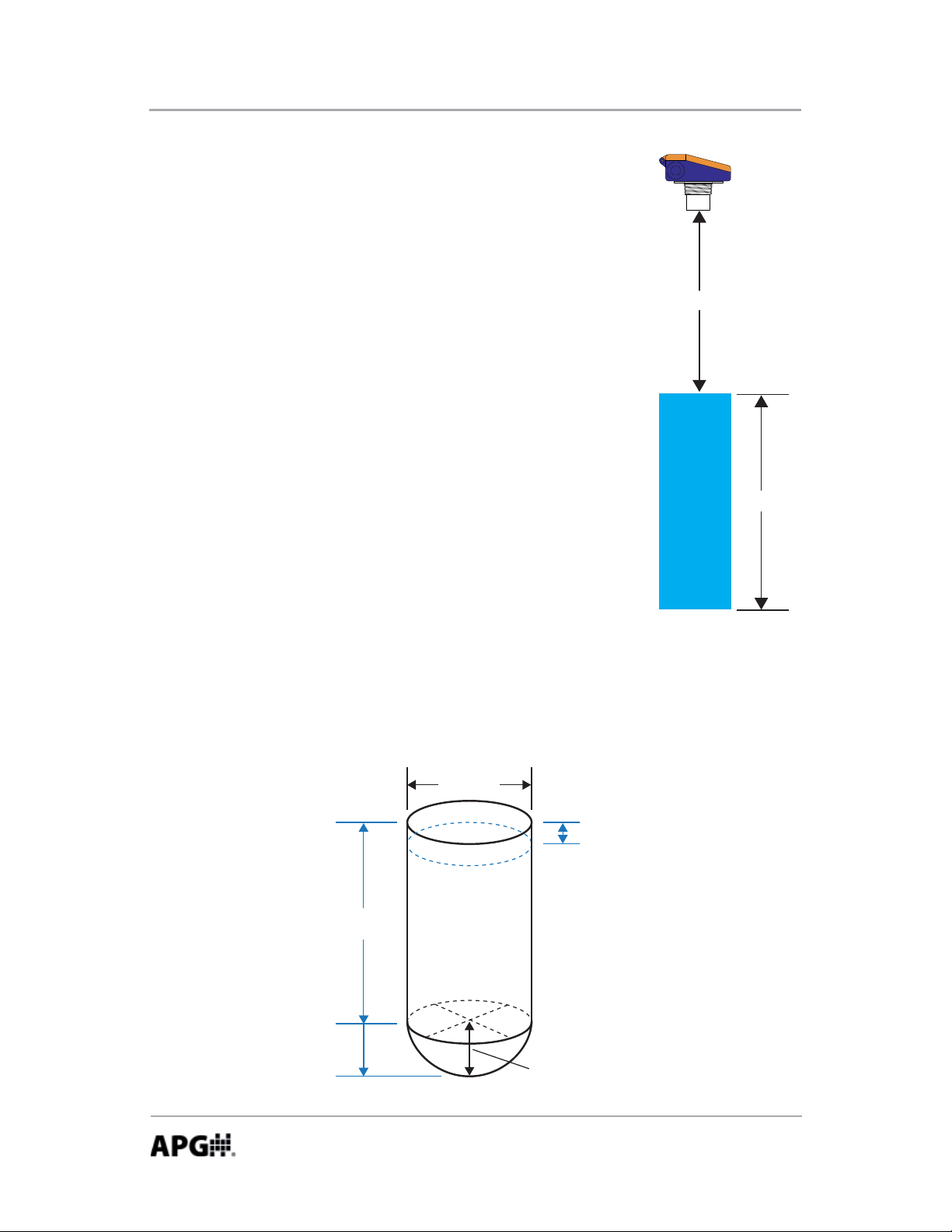
2 = Standing Cylindrical Tank with Hemispherical Bo om
Enter all dimensions shown below into the Tank Parameter fi elds and select the
desired Volume Units.
Diameter
Full
Distance
Empty
Distance
or
ŽƩŽŵ
Radius
20
Automation Products Group, Inc.
APG...Providing tailored solutions for measurement applications
Tel: 1/888/525-7300 • Fax: 1/435/753-7490 • www.apgsensors.com • sales@apgsensors.com
Page 21

Rev. B, 1/12 LOE Series
3 = Standing Cylindrical Tank with Conical Bo om
Enter all dimensions shown below into the Tank Parameter fi elds and select the
desired Volume Units.
Diameter
Full
Distance
Empty
Distance
Cone
Length
Cone
Diameter
4 = Standing Rectangular Tank with Chute
Enter all dimensions shown below into the Tank Parameter fi elds and select the
desired Volume Units.
Full
Distance
Empty
Distance
or
Tank X
Tank Y
Chute
Length
Chute Y
Chute X
Automation Products Group, Inc.
APG...Providing tailored solutions for measurement applications
Tel: 1/888/525-7300 • Fax: 1/435/753-7490 • www.apgsensors.com • sales@apgsensors.com
21
Page 22

LOE Series Rev. B, 1/12
5 = Horizontal Cylindrical Tank with Spherical Ends
Enter all dimensions shown below into the Tank Parameter fi elds and select the
desired Volume Units.
Full
Distance
Diameter
End
Radius
Length
Empty
Distance
6 = Spherical Tank
Enter all dimensions shown below into the Tank Parameter fi elds and select the
desired Volume Units.
Full
Distance
Empty
Distance
Diameter
7 = Pounds: allows the user to apply a conversion mul plier to the calculated
level reading. The conversion Mul plier is entered in Tank Parameter 1.
Example: suppose the level depth is calculated to be 5.45 feet (based on
the Empty Distance se ng). If the conversion Mul plier is set to 7.150, the
calculated result would be (7.15 x 5.45) 38.968.
Automation Products Group, Inc.
APG...Providing tailored solutions for measurement applications
22
Tel: 1/888/525-7300 • Fax: 1/435/753-7490 • www.apgsensors.com • sales@apgsensors.com
Page 23

Rev. B, 1/12 LOE Series
9 = Ver cal Oval Tank
Enter all dimensions shown below into the Tank Parameter fi elds and select the
desired Volume Units.
Full
Distance
Empty
Distance
Width
Depth
Length
10 = Horizontal Oval Tank
Enter all dimensions shown below into the Tank Parameter fi elds and select the
desired Volume Units.
Full
Distance
Empty
Distance
Depth
Length
Width
Automation Products Group, Inc.
APG...Providing tailored solutions for measurement applications
Tel: 1/888/525-7300 • Fax: 1/435/753-7490 • www.apgsensors.com • sales@apgsensors.com
23
Page 24

LOE Series Rev. B, 1/12
Volume Units: selects the unit of measure for the volumetric Applica on
Types (types 2-6, 9, 10).
1 = Feet^3
2 = Million feet^3
3 = Gallons
4 = Meters^3
5 = Liters
Tank Parameters: used to enter tank dimensions or the conversion mul plier,
depending on the Applica on Type selected (see Applica on Types for more
informa on).
NOTE: the Tank Parameter labels will automa cally change to refl ect the
parameters required for the Applica on Type selected.
Units: selects the Units of measurement for the distance or level Applica on
Type (types 0 or 1), and sets the Units of measure to be used for all parameters
requiring dimensional value.
1 = Feet
2 = Inches
3 = Meters
24
Automation Products Group, Inc.
APG...Providing tailored solutions for measurement applications
Tel: 1/888/525-7300 • Fax: 1/435/753-7490 • www.apgsensors.com • sales@apgsensors.com
Page 25

Rev. B, 1/12 LOE Series
Modbus
The LOE has the capability to interface with up to 10 of APG’s Modbus based
sensors. The LOE acts as the Master device, querying the Modbus sensors and
repor ng their readings to the website along with the LOE’s own readings.
NOTE: each Modbus sensor will show up on the website as a sub-sensor to
it’s LOE master. For example, if the LOE’s serial number is L00001219, then
Modbus sensor 1 would be displayed as L00001219_1 and so forth.
RS-485 Modbus Input 1 & 2
These pages are used to confi gure the parameters of Modbus sensor currently
selected (see “Sensor Number to View” under “RS_485 Network Se ngs”
page). Not all parameters are applicable to every Modbus sensor. Refer to the
Modbus sensor’s user manual for parameter descrip ons.
RS-485 Modbus Holding Registers
This page is available to view the readings of the Modbus sensor that is currently selected.
Modbus TCP/IP
Using the LOE’s IP address and port number 502, the LOE’s readings can be
polled at address number 11 on registers 30303-30304.
Example:
0001: Transac on Iden fi er
0000: Protocol Iden fi er
0006: Message Length (6 bytes to follow)
0B: The Unit Iden fi er (0B hex = 11)
04: The Func on Code (read Holding Registers)
012E: The Data Address of the fi rst register requested. (12E hex = 303)
0002: The total number of registers requested. (read 2 registers; 303 to 304)
Byte order (hex values)
00 01 00 00 00 06 0B 04 01 2E 00 02
Automation Products Group, Inc.
APG...Providing tailored solutions for measurement applications
Tel: 1/888/525-7300 • Fax: 1/435/753-7490 • www.apgsensors.com • sales@apgsensors.com
25
Page 26

LOE Series Rev. B, 1/12
RS-485 Se ngs
Baud Se ngs: selects the communica on baud rate between the LOE and the
a ached Modbus sensors. Refer to the Modbus sensor’s documenta on for
the appropriate se ng (typically 9600 Baud).
Number of Sensors On Line: sets the number of Modbus sensors that are connected to the LOE.
Sensor Number to View: used to select the sensor number to be viewed or
programmed (also see “New Sensor Number” below). The parameters of the
selected sensor will populate the RS-485 Modbus Input pages, and the sensor’s
readings can be viewed in the RS-485 Holding Register page.
New Sensor Number: used to change the sensor number of the sensor currently being viewed (see “Sensor Number to View” above). Each Modbus sensor connected to the LOE must be assigned a unique sensor number (0 to 10).
Duplicate sensor numbers will cause errors in communica on.
Delay Between Call-in Times: sets the delay between cycles of querying all attached Modbus sensors.
26
Automation Products Group, Inc.
APG...Providing tailored solutions for measurement applications
Tel: 1/888/525-7300 • Fax: 1/435/753-7490 • www.apgsensors.com • sales@apgsensors.com
Page 27

Rev. B, 1/12 LOE Series
Using the levelandfl ow.com website
APG’s www.levelandfl ow.com website provides access to sensor readings, as
well as the capability to setup email/text-message alerts and remotely adjust
sensor parameters (dependent on assigned user access rights).
General Naviga on
Sites Tab: Displays the list of sites assigned to the user.
Click on a site box to view the list of the sensors that are assigned to that site.
Click on an individual sensor to access the readings data as well as to adjust
sensor parameters (for those with access rights).
Profi le Tab: allows the user to manage their profi le.
NOTE: the La tude, Longitude and Zoom se ng are for se ng your default
view when entering the Google Maps feature. Simply click the Set bu on,
fi nd your loca on on the map and click on the loca on to set a marker.
Ensure the zoom at the desired level and click the “Set User’s Google map
start loca on” bu on to save the loca on.
Data Logging and Retrieval
Begin Date and End Date: Used to set the me period for the data to be
retrieved.
Chart: Retrieves the data in the form of a line chart.
Excel: Retrieves the data as an Microso Excel fi le.
View Data: Retrieves a list of sensor readings along with the associated me
stamp.
Alarm History: displays a list of alarms that have previously occured.
View Parameters: displays a list of all sensor parameters as of the last me the
sensor logged into the website.
Automation Products Group, Inc.
APG...Providing tailored solutions for measurement applications
Tel: 1/888/525-7300 • Fax: 1/435/753-7490 • www.apgsensors.com • sales@apgsensors.com
27
Page 28

LOE Series Rev. B, 1/12
Sensor Se ngs
Edit Info: allows the user to assign descrip on tags, set me zone informa on,
and set a sensor loca on on the Google Maps feature.
Se ng the Sensor Google Maps Loca ons: click on the “Edit Info” bu on and
then click the “Set” bu on, fi nd the sensor’s loca on on the map and click on
it’s loca on to set a marker. Ensure the zoom at the desired level and click
the “Set sensors Google map loca on” bu on to save the loca on.
Edit Parameters: allows users (with access rights) to adjustment sensor
parameters.
NOTE: parameter changes made from the website will only take eff ect a er
the LOE reports to the website at the next scheduled call-in interval.
Edit Alarms: allows users (with access rights) to add alarms to send email or
text message alerts whenever an alarm condi on occurs and when the alarm
condi on clears (see website “Se ng Website Alarms” sec on below).
Website Alarms
There are three diff erent types of website alarms: Immediate, Interval, and
Heartbeat. Refer to descrip ons below.
Immediate Alarms: results from an alarm condi on on one of the LOE’s solid
state relays (Trip 1 & Trip 2). If one of the trip relays enters an alarm condi on,
the LOE will report the alarm to the website without wai ng for the next
scheduled call-in interval.
NOTE: in addi on to se ng an alarm on the website, the LOE’s trip relays
must also be confi gured for website alarming. See “Confi guring the LOE for
Website Alarms” on page X for details.
28
Automation Products Group, Inc.
APG...Providing tailored solutions for measurement applications
Tel: 1/888/525-7300 • Fax: 1/435/753-7490 • www.apgsensors.com • sales@apgsensors.com
Page 29

Rev. B, 1/12 LOE Series
Interval Alarms: alarm condi on is based solely on the sensor readings as
reported at the scheduled call-in interval. i.e. the alarm is a func on of the
website and is not generated by the sensor itself.
Heartbeat Alarm: once every 4 hours the website checks the call-in status of all
sensors that have been assigned a heartbeat alarm. If the LOE missed the last
scheduled login, an alert message would then be sent to no fy the user(s) that
the sensor is not reported to the website.
Immediate Alarm Se ngs
NOTE: the trip relay(s) must be confi gured for website alarming. See
“Confi guring the LOE for website alarms” on page
Label: sets the alarm label that will be included in the alert message tle.
X for details.
Message: allows the user to enter a brief message that will be included in the
body of the email or text alert message.
Call Type: selects the type of alert message to be sent. If “None” is selected,
the alarm condi on will show on the website but no message will be sent.
Sent: (view only) shows the status of the Delay count (see Delay below).
Delay: sets the number of mes the alarm must ac vate before an alarm
message will be sent. Se ng the Delay to 0 will disable the alarm.
Auto Clear: when checked, the Delay count will reset to 0 and begin again at
the end of each cycle, resul ng in a new alert message each me the Delay
count is reached. If Auto Clear is unchecked, the alert message will be sent
when the Delay count is reached, but no further messages will be sent unless
the alarm condi on clears and then reac vates and is processed though the
Delay count fi lter. If the alarm condi on clears and Auto Clear is unchecked, an
“Alarm Clear” message will be sent to the contact.
Contact: selects the user to receive the alert message (based the email address
and/or cell phone number in their user profi le).
Automation Products Group, Inc.
APG...Providing tailored solutions for measurement applications
Tel: 1/888/525-7300 • Fax: 1/435/753-7490 • www.apgsensors.com • sales@apgsensors.com
29
Page 30

LOE Series Rev. B, 1/12
Interval Alarm Se ngs
Label: sets the alarm label that will be included in the alert message tle.
Message: allows the user to enter a brief message that will be included in the
body of the email or text alert message.
Call Type: selects the type of alert message to be sent. If “None” is selected,
the alarm condi on will show on the website but no message will be sent.
Alarm Point: defi nes the value (in the unit of measure of the sensor reading)
for the alarm condi on. If the box below is checked, the alarm condi on will
occur whenever the sensor reading is greater than the Alarm Point value. If
le unchecked, the alarm condi on will be whenever the sensor reading is less
than the Alarm Point value.
Off set Clear: sets an off set, star ng from the Alarm Point and extending away
from the alarm zone, that must be reached before the alarm condi on will
clear. This is to prevent repeated alarm cha er if the target is fl uctua ng back
and forth across the Alarm Point.
Sent: (view only) shows the status of the Delay count (see Delay below).
Delay: sets the number of mes the alarm must ac vate before an alarm
message will be sent. Se ng the Delay to 0 will disable the alarm.
Auto Clear: when checked, the Delay count will reset to 0 and begin again at
the end of each cycle, resul ng in a new alert message each me the Delay
count is reached. If Auto Clear is unchecked, the alert message will be sent
when the Delay count is reached, but no further messages will be sent unless
the alarm condi on clears and then reac vates and is processed though the
Delay count fi lter. If the alarm condi on clears and Auto Clear is unchecked, an
“Alarm Clear” message will be sent to the contact.
Contact: selects the user to receive the alert message (based the email address
and/or cell phone number in their user profi le).
Automation Products Group, Inc.
APG...Providing tailored solutions for measurement applications
30
Tel: 1/888/525-7300 • Fax: 1/435/753-7490 • www.apgsensors.com • sales@apgsensors.com
Page 31

Rev. B, 1/12 LOE Series
Heartbeat Alarm Se ngs
Label: sets the alarm label that will be included in the alert message tle.
Message: allows the user to enter a brief message that will be included in the
body of the email or text alert message.
Call Type: selects the type of alert message to be sent. If “None” is selected,
the alarm condi on will show on the website but no message will be sent.
Sent: (view only) shows the status of the Delay count (see Delay below).
Delay: sets the number of mes the alarm must ac vate before an alarm
message will be sent. Se ng the Delay to 0 will disable the alarm.
Auto Clear: when checked, the Delay count will reset to 0 and begin again at
the end of each cycle, resul ng in a new alert message each me the Delay
count is reached. If Auto Clear is unchecked, the alert message will be sent
when the Delay count is reached, but no further messages will be sent unless
the alarm condi on clears and then reac vates and is processed though the
Delay count fi lter. If the alarm condi on clears and Auto Clear is unchecked, an
“Alarm Clear” message will be sent to the contact.
Contact: selects the user to receive the alert message (based the email address
and/or cell phone number in their user profi le).
Adding a new contact to an exis ng alarm
If more than one contact needs to receive an email and/or text message alert, a
duplicate alarm must be added and assigned to the new contact. Simply select
the alarm you wish to duplicate, click on the “Copy” bu on, select the new
“Contact”, and click the “Add” bu on.
Automation Products Group, Inc.
APG...Providing tailored solutions for measurement applications
Tel: 1/888/525-7300 • Fax: 1/435/753-7490 • www.apgsensors.com • sales@apgsensors.com
31
Page 32

LOE Series Rev. B, 1/12
Sensor Reset
Cau on! Performing the following procedure will reset all Network se ngs,
including disabling the DHCP. A crossover Ethernet cable will be required to
access the LOE’s internal webpage and re-enable the DHCP.
Disconnected the sensor from power. Press and hold down the reset bu on
while reapplying power. Con nue to hold the bu on for another 10 seconds
a er applying power. The LOE is now reset to default parameter values. In
order to access the internal webpage, follow the instruc ons below:
Computer Setup:
1. Click Start, Control Panel, and then open the Network Connec ons.
2. Right click on the Local Area Connec on and click Prope es.
3. In the center box scroll down and select Internet Protocol (TCP/IP) and then
click the Proper es bu on.
4. Select Use the following IP address and enter in the following:
IP Address: 169.254.0.201
Subnet Mask: 255.255.255.0
NOTE: if “Use the following IP address” is already checked and network
parameters have been assigned, contact your network administrator for
assistance.
LOE Setup:
5. Connect the sensor to a computer’s Ethernet port using a crossover Ethernet
cable.
NOTE: if a POE-injector is being used, the crossover cable will be between
the computer and the injector’s LAN port. Use a standard Ethernet cable
between the injector’s LAN+DC port and the LOE.
6. Apply power to the LOE. The sensor should start cking and the COM LED
should fl ash approximately every 30 seconds.
32
Automation Products Group, Inc.
APG...Providing tailored solutions for measurement applications
Tel: 1/888/525-7300 • Fax: 1/435/753-7490 • www.apgsensors.com • sales@apgsensors.com
Page 33

Rev. B, 1/12 LOE Series
7. Open the computer’s Internet browser and enter the LOE’s default IP address
192.254.0.200 into the browser address bar (i.e., h p://169.254.0.200). This
should bring up the LOE’s Internal webpage.
8. Enter the Network Se ngs page and check the boxes to enable the External
webpage Access and the DHCP, then click “Change”. The sensor will no longer
respond.
9. Disconnect the LOE from the computer and use a standard Ethernet cable
to connect the LOE to a connec on that provides access to the Internet. A er
a few seconds, the Com LED should illuminate and remain solid, indica ng the
LOE has established communica on with the website.
10. Go back to step 1-3 and change the computer Ethernet port’s Internet
Protocal proper es back to “Obtain an IP address automa cally”.
Automation Products Group, Inc.
APG...Providing tailored solutions for measurement applications
Tel: 1/888/525-7300 • Fax: 1/435/753-7490 • www.apgsensors.com • sales@apgsensors.com
33
Page 34

LOE Series Rev. B, 1/12
Specifi ca ons
Opera ng Range
LOE-2126 .....................................1 to 25 feet (305 to 7620 mm)
LOE-3136 .....................................1.5 to 40 feet (457 to 12192 mm)
LOE-6126 .....................................6 to 180 inches (152 to 4572 mm)
Opera ng Voltage ............................48 VDC Power over Ethernet (POE); requires
POE injector or switch
Total Current Draw ..........................40mA @ 48 VDC
Maximum Power Ra ng ..................2.0 W
Ra ngs .............................................IP65
Available Outputs ............................Ethernet TCP/IP to internal web page or
APG website
Ethernet TCP/IP Modbus
2 - Isolated solid state relays (400 V, 130 mA
max.)
Resolu on .......................................0.1 in. (2.54 mm)
Accuracy ..........................................+/- 0.25% of range with no temp gradient
Sensor Adjustments ........................Programmable modes via website
Transducer Type ..............................Flat ceramic sealed PVDF face
Opera ng Temperature ...................-40 to 140°F (-40 to 60°C)
Sample Rate.....................................1 to 12 Hz
Beam Pa ern ...................................9° off axis
Cable Connec on ............................RJ-45 + terminal strip for relaysf
34
Automation Products Group, Inc.
APG...Providing tailored solutions for measurement applications
Tel: 1/888/525-7300 • Fax: 1/435/753-7490 • www.apgsensors.com • sales@apgsensors.com
Page 35
Rev. B, 1/12 LOE Series
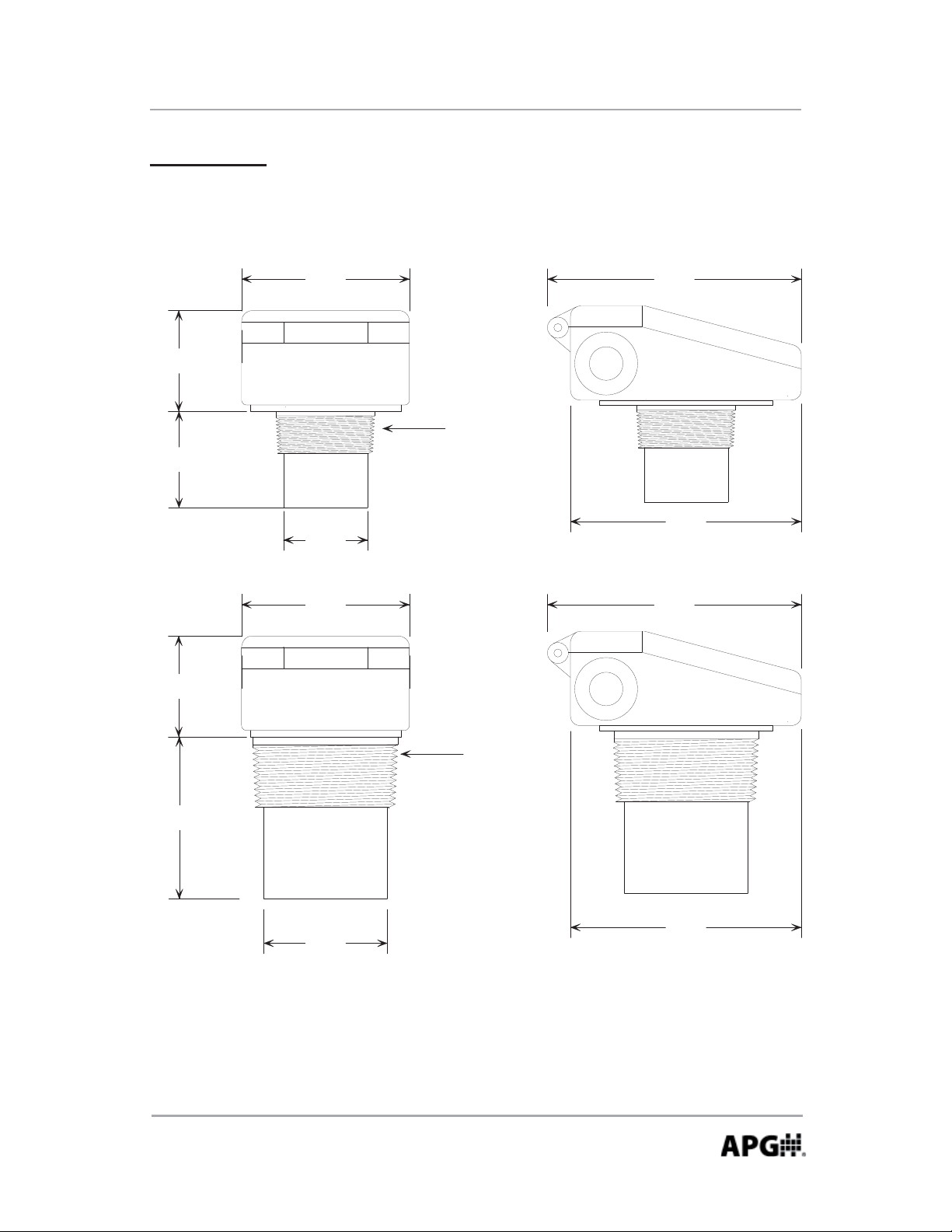
Dimensions
LOE-2126 & 6126
4
.
0
0
"
2
.
4
0
"
T
P
N
"
2
2
.
3
0
"
2
.
"
0
0
LOE-3136
6
.
0
5
"
"
5
.
5
0
0
"
4
.0
0
"
.4
2
T
P
N
3
"
6
"
3
.
8
"
3
.
0
0
"
5
6
.0
0
"
5
.
5
Automation Products Group, Inc.
APG...Providing tailored solutions for measurement applications
Tel: 1/888/525-7300 • Fax: 1/435/753-7490 • www.apgsensors.com • sales@apgsensors.com
35
Page 36

AUT OMATION
PRODUCTS
GROUP, INC.
APG...Providing tailored solutions
for measurement applications
Automation Products Group, Inc.
Tel: 1/888/525-7300
1/435/753-7300
Fax: 1/435/753-7490
e-mail: sales@apgsensors.com
www.apgsensors.com
Automation Products Group, Inc.
1025 W. 1700 N.
Logan, UT 84321
 Loading...