

Page 1

APG
True Echo
™
Guided Wave Radar Level Transmitter
User Manual
For the GWR200
R
Doc #9004784
Rev A, 05/2016
Page 2

Table of Contents
Introduction ................................................................................................................ iii
Warranty and Warranty Restrictions .................................................................... iv
Chapter 1: Specications and Options ....................................................................1
Dimensions ........................................................................................................................................1
Specications ...................................................................................................................................2
Model Number Congurator ......................................................................................................... 3
Wiring Diagram ................................................................................................................................ 4
Chapter 2: Installation and Removal Procedure and Notes ................................5
Tools Needed ....................................................................................................................................5
Installation Notes ............................................................................................................................ 5
Tensile Forces .................................................................................................................................. 5
Mounting Instructions .................................................................................................................. 6
Electrical Installation ....................................................................................................................6
Powering on the True Echo™ ......................................................................................................... 6
Software Installation ...................................................................................................................... 6
Removal Instrustions ..................................................................................................................... 7
Chapter 3: Communications and Programming .................................................... 7
True Echo™ Communication Tool ................................................................................................. 7
Setup ................................................................................................................................................... 7
Navigation Window Options ..........................................................................................................8
True Echo™ Communication Software Overview .................................................................9-12
Chapter 4: Maintenance ...........................................................................................13
General Care .................................................................................................................................... 13
Repair and Returns ........................................................................................................................ 13
ii
Tel: 1/888/525-7300 • Fax: 1/435/753-7490 • www.apgsensors.com • sales@apgsensors.com
Page 3

Introduction
Thank you for purchasing a True Echo™ Guided Wave Radar level transmitter from APG. We appreciate your
business and your trust. Please take a few minutes to familiarize yourself with your True Echo™ and this
manual.
The True Echo™ GWR200 takes the mystery and frustration out of level measurement. With programmable
4-20 mA or RS-485 Modbus outputs, and innovative signal analysis, the True Echo™ can accurately measure
solids, liquids, and slurries at depths up to 80 feet. NEMA 6 housing is standard, and 316 SS or PFTE-coated
316 SS probes operate in process temperatures from -40° to 398° F. Robust and reliable, the True Echo™
makes dicult level measurements easy.
Reading your label
Every APG sensor comes with a label that includes the instrument’s model number, part number, and serial
number. Please ensure that the part number on your label matches your order.
Tel: 1/888/525-7300 • Fax: 1/435/753-7490 • www.apgsensors.com • sales@apgsensors.com
iii
Page 4

Warranty and Warranty Restrictions
This product is covered by APG’s waranty to be free from defects in material and workmanship under
normal use and service of the product for 24 months. For a full explanation of our Warranty, please visit
https://www.apgsensors.com/about-us/terms-conditions. Contact Technical Support to recieve a Return
Material Authorization before shipping your product back.
Scan the QR code below to read the full explanation of our Warranty on your tablet or smartphone.
iv
Tel: 1/888/525-7300 • Fax: 1/435/753-7490 • www.apgsensors.com • sales@apgsensors.com
Page 5
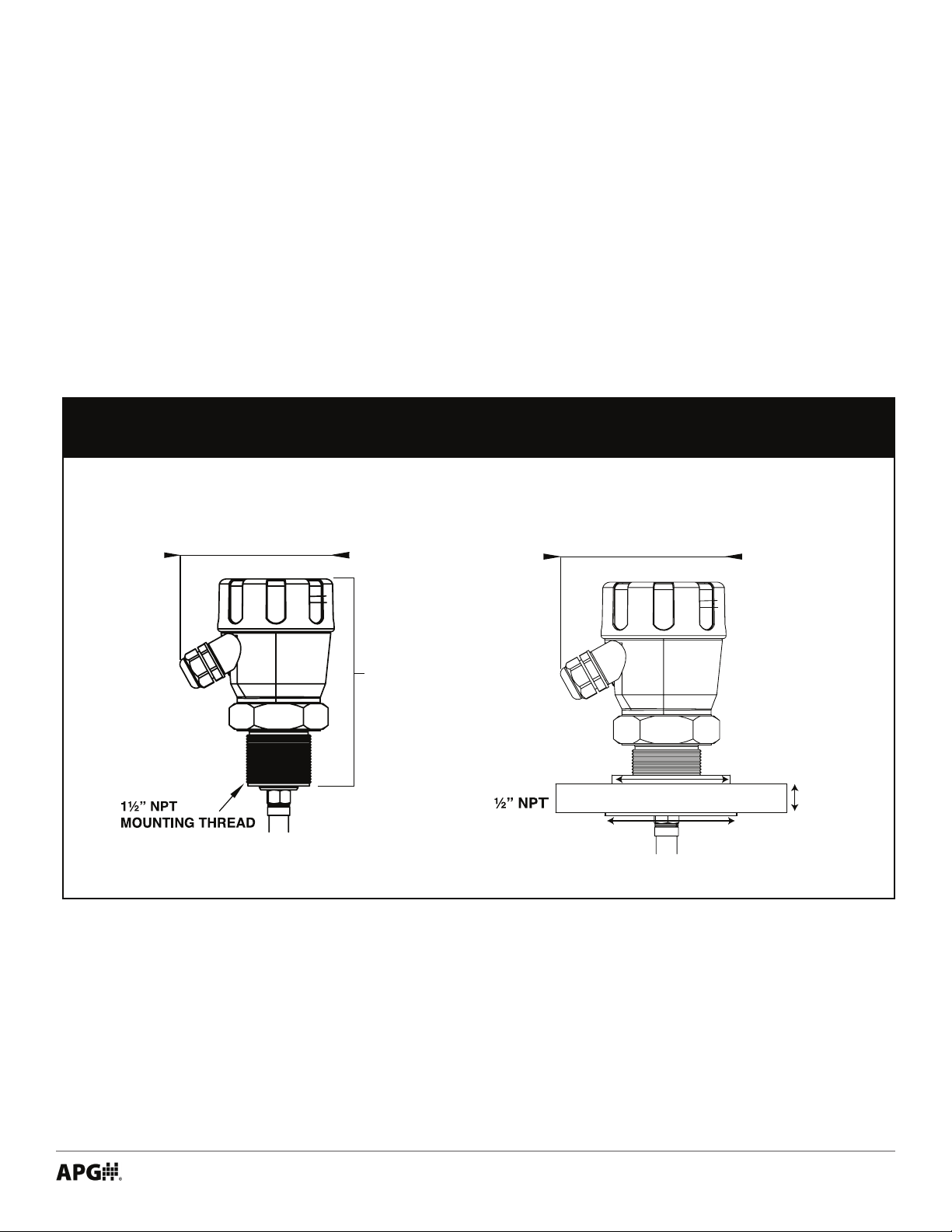
Chapter 1: Specications and Options
• Dimensions
NEMA 6 ENCLOSURE
Standard
4.3” (110mm) 4.3” (110mm)
6” (154mm)
Flange Option
2-9/16” (65mm)
7/8”
(22mm)
2-7/8” (73mm)
Tel: 1/888/525-7300 • Fax: 1/435/753-7490 • www.apgsensors.com • sales@apgsensors.com
1
Page 6

• Specications
Performance
Measurement Range 1.25’ to 80’ with minimum dielectric constant of 0.3
Communications
Communications RS485 Modbus
Response Time 100 samples/sec/updated <100 millisec.
Electrical
Output 4-20mA, Isolated 4-20 mA
Loop Resistance 750 ohms (current loop 24VDC supply)
250 ohms (isolated 24 VDC supply)
Operating Voltage 12-30 VDC
Power Consumption <3W @ 24 VDC
Accuracy
Accuracy +/- 0.039” ( 1 mm) or 0.02% of measured distance,
whichever is greatest.
Repeatability +/- 0.02” (0.5mm)
Ambient Temp. Eect +/- 0.005”/K of measured value
Environmental
Maximum Operating Temperature Electronics: -40º to 158ºF (-40° to 70ºC)
Process/Probe: -40º to 398ºF (-40° to 203ºC)
Maximum Operating Pressure -14.50 PSI to 580 PS
Enclosure NEMA 6: Coated Epoxy Aluminum with IP67 Sealing
Materials of Construction
PFTE-coated 316 SS, 0.395” ø
Wire Cable Probe: 316 SS, 0.195” ø
PFTE-coated 316 SS, 0.34” ø
Weighted Assembly: 0.75” diameter
Tensile Load 4,270 lbs max
Probe Type/Diameter Rod Probe: 316 SS, 0.25” ø
Mounting
Process Connection/Type Standard: 1.50” MNPT
Option: 1.50” ANSI 150lb. Flange
Cable Entries (2) 1/2” NPT Conduit Entries
2
Tel: 1/888/525-7300 • Fax: 1/435/753-7490 • www.apgsensors.com • sales@apgsensors.com
Page 7

• Model Number Congurator
Model Number: GWR200 - ____ - _____ - _____ - _____ - _____ - _____ - _____
A B C D E F G
A. Wiring Option
□ 4 4-wire
B. Probe Type
□ R 316 SS Rod (120” max)
□ T 316 SS PTFE Coated Rod (120” max)
□ W Wire Cable (960” max)
□ X PTFE Coated Wire Cable (960” max)
C. Enclosure Rating
□ N6 NEMA 6
D. Process Connection
▲
□ 0
1.5” NPT
□ 1 1.5” ANSI 150# Flange
▲
This option is standard
E. Conduit Entries
▲
□ 1
Two 1/2” NPT
□ 2 Two Cable Glands
□ 3 One 1/2” NPT, One Cable Gland
F. Probe Length
□ ___ Probe Length in Inches (15” to 120” or 960”)
G. Options
▲
□ NN
None
□ 04 PTFE Isolation Gasket
Tel: 1/888/525-7300 • Fax: 1/435/753-7490 • www.apgsensors.com • sales@apgsensors.com
3
Page 8

• Wiring Diagram
Isolated 4-20 mA Circuit
True Echo
Terminals
4-20mA-
4-20mA+
IS+
4
Comm A
Comm B
DC In +
DC In -
9
10
Isolated 4-20mA Output
TX A-
TX B+
Modbus
Network Node
TX A-
TX B+
4-20 mA
CURRENT
LOOP
Supply Voltage
Note: Modbus Network connection
is seperate from supply voltage and
4-20 mA output.
Process
Controller
DC Gnd
R
L
+
DC Gnd
4
Tel: 1/888/525-7300 • Fax: 1/435/753-7490 • www.apgsensors.com • sales@apgsensors.com
Page 9

Chapter 2: Installation and Removal Procedures and Notes
• Tools Needed
• Appropriately sized wrenches for sensor installation and for probe connection
• Flathead screwdriver for wire connections
• Installation Notes
The True Echo™ GWR200 should be installed in an area--indoors or outdoors--which meets the following
conditions:
• Ambient temperature between -40º to 158ºF (-40° to 70ºC)
• Ample space for maintenance and inspection
Additional care must be taken to ensure:
• The probe is securely fastened to the sensor prior to installing the sensor on the tank or vessel
• The sensor is mounted away from tank or vessel walls and inlets
• The probe is free from obstructions such as inows and agitators
• The sensor threading is started by hand to avoid cross-threading
NOTE: Do not mount the sensor where the probe will interact with objects such as ll
streams, pipes, ladder rungs, outlet ow, or agitators.
• Tensile Forces
Tensile forces are heavily dependent on the viscosity and abrasive characteristics of the product in the
vessel. Ensure the tensile loading is appropriate for the silo cover and mounting structure. The maximum
tensile load of the cable probe is 4,275 pounds.
Tel: 1/888/525-7300 • Fax: 1/435/753-7490 • www.apgsensors.com • sales@apgsensors.com
5
Page 10

• Mounting Instructions
Mounting your True Echo™ GWR200 is easy if you follow a few simple steps:
• Securely connect probe to sensor head prior to mounting sensor.
• Carefully feed probe through mounting hole
• Ensure that probe hangs free from obstructions
• Begin threading sensor NPT connection by hand
• Finish with wrench as necessary
• Electrical Installation
• Remove the screw-on lid of the True Echo™.
• Feed the cable(s) into the True Echo™ via the 1/2” NPT or cable glands.
• Attach the wires of your control system to the True Echo™ terminal block according to the pinout table
on page 4.
• Replace the screw-on lid.
• Powering the True Echo™ for the First Time
1) Conrm the True Echo™ is mounted within the recommended specications.
2) Conrm the wiring is correct and all connections are as shown in page 4.
3) Apply power to the True Echo™.
4) The True Echo™ will take up to 30 seconds to warm up and stabilize upon initial startup. It will then perform a scan to locate the level which will take approximately 1 second or less. Once the load sequence is
complete and the True Echo™ has taken the rst measurement scan, the analog output should indicate the
material level (factory default) or distance measurement. If the proper analog output is not achieved please
contact the factory for further instructions.
• Software Installation
• Download True Echo™ Software and windows driver ziple from https://www.apgsensors.com/support.
• Open the zip le.
• Choose “Install” from the options at the top of the zip le window.
• The software will create True Echo.exe which will run from a folder in your Start Menu titled “APG”.
6
Tel: 1/888/525-7300 • Fax: 1/435/753-7490 • www.apgsensors.com • sales@apgsensors.com
Page 11

• Removal Instructions
• Ensure that power to the sensor is o.
• Remove screw-on lid, disconnect wires and remove cable(s). Replace lid.
• Carefully unscrew sensor from mounting.
• Lift sensor from tank and carefully back probe out of tank.
• Remove the sensor and store it in a dry place, at a temperature between -40° F and 158° F.
Chapter 3: Communications and Programming
• True Echo™ Communication Tool
The True Echo™ Communication Tool can be used in tandem with the APG True
Echo™ Software to program and control your True Echo™ Level Transmitter.
Through the True Echo™ Software, you can monitor the raw readings from the
sensor, or congure multiple sensors.
• Setup
Connect the True Echo™ Communication Tool to the Modbus Network Terminals shown on page 4. Connect
A on the True Echo™ Communication Tool to Comm A (TX A-) and B to Comm B (TX B+).
Connect the USB side of the True Echo™ Communication Tool to a USB port on your PC.
Double click the True Echo™ icon on your desktop or in your Start Menu.
The Navigation Window
Tel: 1/888/525-7300 • Fax: 1/435/753-7490 • www.apgsensors.com • sales@apgsensors.com
7
Page 12

• Navigation Window Options
MENU SELECTION DESCRIPTION OPTIONS
File Load and save custom application settings Load / Save current setting
Load Application setting
View Adjust view settings, access options menu Toolbar
Status Bar
Options
™
Help Access Help le & display True Echo
version info Help
About
Connect Attempts to open communication or terminate
communication with unit
DeviceID Select DeviceID (if using comms networked units with
unique IDs assigned)
Setup When connected the setup menus will be listed under
the arrow button to the right
Diag When connected this opens the Diagnostic window
where you can view live echo proles and operational
diagnostics and measurements.
NewView If you have multiple True Echo
™
units connected to a
single network you can view the basic measurement
Flash For updating unit software. This button is locked
Connect
Disconnect
Adjustable via Client
Information in ‘Options’ menu
Info Screen
Quick Set
Output Adjust
Advanced
Report This button can generate a PDF report of the current
settings & serial numbers of the unit or view the settings
of a stored report
8
Tel: 1/888/525-7300 • Fax: 1/435/753-7490 • www.apgsensors.com • sales@apgsensors.com
Preview current setup
Preview stored setup
Page 13

• True Echo™ Communication Software Overview
The True Echo™ Software is included with the Communication Tool for easy setup and diagnostics of
the True Echo™. This tool will allow the user interface into the programming, setup and diagnostics tools
imbedded within the True Echo™ program. The True Echo™ GWR Level Transmitter has advanced auto-tuning
parameters that adjust the unit’ s sensitivity (to changing dielectric, mounting and obstructions) and gain
settings so the user does not have to preform any initial startup settings. Please contact the factory if there
is a requirement or question regarding the True Echo™ Communication Software.
Fig. 1) The Diagnostics Menu allows the user to see how the return echo is preforming and make
adjustments to the measurement signal.
Tel: 1/888/525-7300 • Fax: 1/435/753-7490 • www.apgsensors.com • sales@apgsensors.com
9
Page 14

Fig. 2) The Tank View Menu allows the user to view their application activity.
The Quickset menu (g 3) is found on the dropdown arrow
of the Setup button. The Quickset menu contains the basic
parameters required to get the unit up and running. It is one
of the three main menu options in the internal software. The
menu will provide elds which the user can edit by clicking in
the eld and re-entering the correct value.
Low Level (ft): Enter the distance in feet between the
connection point of the True Echo™ and the end of the probe.
Hi Level (ft): Enter the distance in feet between the
connection point of the True Echo™ and the highest point of
level (must be at least 1.1ft)
Fail Safe: Enter a set failsafe output from the dropdown box.
Fail Safe Time: Enter the amount of time (in seconds) the
unit will wait in a fail mode (set countdown clock) before
outputting a fail mode set milliamp value.
Fig. 3) The Quick Setup Menu sets the
application base parameters.
Fill Speed: Select the applications ll speed
Read All Parameters
Green Cell
Red Cell
10
To refresh any menu
Damp Fill: Select the amount of dampening upon tank lling
for stable reading
Read / write successful
Read / write failed
Tel: 1/888/525-7300 • Fax: 1/435/753-7490 • www.apgsensors.com • sales@apgsensors.com
Page 15

Empty Speed: Select the applications empty speed
Damp Empty: Select the amount of dampening upon tank empty for stable reading
DispMode: Select the default display mode in; Space, Material Level or % of Material
Lock Code: Enter in a pass code number from 0 to 200
Fig. 4) Info Screen with device information
Advanced parameters are for adjusting primary sensitivity,
echo controls and lters and executing the auto
calibration routines as well as factory resets.
Digital Bias (%): Sets the amount of digital signal and
sensitivity to mapping range. The higher the percentage
increases the digital bias or lter. This parameter is auto
set and typically does not require adjustment, but can be
manually set.
Gain (%): Increase or decrease the amplication of
the signal detected by the Sensitivity routines and
adjustments. This parameter is auto set and typically does
not require adjustment.
Sens Max (%): Adjust the peak Sensitivity cap. This value
will be auto set by the Digitize calibration routine.
Sensitivity: The primary adjustment for the unit to detect
level accurately. This value is auto set by the Digitize
calibration routine but can be manually adjusted.
Fig. 5) The Advanced Setup Menu allows the user to
ne tune the measurement signal and preform a
Digitze TDR command for auto tuning in the aplication
Echo Size (V): Sets the target echo size that the unit is
attempting to maintain. Any signal which is detected by the Sensitivity setting will be either full signal (2.5V)
or less. If the signal detected by Sensitivity is less than Echo Size, than the unit uses gain to amplify the signal
to the Echo Size.
Threshold (V): Adjust the amount of lter which tells the unit to ignore any echoes of a signal size less than
this value (in Volts). This can be used a part of troubleshooting (see Troubleshooting false echo elimination).
Blanking (ft): Blanking is the non-measurable zone closest to the process connection. This can be increased
to “Blank” out high false echoes caused by mounting.
Digitize TDR: Perform auto-Digitization of sensitivity based on mounting, tank obstructions and dielectric of
material touching the probe.
Probe Reset: Restores probe settings back to factory default. Most probe settings are in the Advanced Setup
Menu.
Cal. Mount: Performs a digital mapping routine of a user selected span. Used when there is signal
interference at high level or mounting.
Tel: 1/888/525-7300 • Fax: 1/435/753-7490 • www.apgsensors.com • sales@apgsensors.com
11
Page 16

Fig. 4) Factory Menu
12
Tel: 1/888/525-7300 • Fax: 1/435/753-7490 • www.apgsensors.com • sales@apgsensors.com
Page 17

Chapter 4: Maintenance
• General Care
Your level sensor is very low maintenance and will need little care as long as it was installed correctly.
However, in general, you should periodically inspect your True Echo™ GWR200 sensor to ensure the probe is
free of any buildup that might impede the function of the sensor. If sediment or other foreign matter builds
up on the probe, detection errors can occur.
If you need to remove the sensor, be sure to store it in a dry place at a temperature between -40° and 158°
F.
• Repair and Returns
If your True Echo™ GWR200 needs repair, contact us via email, phone, or online chat on our website. We will
issue you an RMA number with instructions.
• Phone: 888-525-7300
• Email: sales@apgsensors.com
• Online chat at www.apgsensors.com
Tel: 1/888/525-7300 • Fax: 1/435/753-7490 • www.apgsensors.com • sales@apgsensors.com
13
Page 18

APG
R
Tel: 1/888/525-7300 • Fax: 1/435/753-7490 • www.apgsensors.com • sales@apgsensors.com
Automation Products Group, Inc.
 Loading...