

Page 1

PRODUCTS
AUTOMATION
Operator’s Manual
GROUP, INC.
FT-100 Series
Mechanically Activated,
Narrow Angle Float Switch
Rev. A3, 6/09
Automation Products Group, Inc.
APG...Providing tailored solutions for measurement applications
Tel: 1/888/525-7300 • Fax: 1/435/753-7490 • www .apgsensors.com • E-mail: sales@apgsensors.com
Page 2

FT-100 Series Rev. A3, 6/09
Table of Contents
Warranty ......................................................................................... 3
Introduction .................................................................................... 4
Specifications .................................................................................. 4
Installation ...................................................................................... 5
Wiring Diagrams............................................................................. 6
Cable Weight................................................................................... 7
Automation Products Group, Inc.
2
APG...Providing tailored solutions for measurement applications
Tel: 1/888/525-7300 • Fax: 1/435/753-7490 • www .apgsensors.com • sales@apgsensors.com
Page 3

Rev. A3, 6/09 FT-100 Series
• Warranty and Warranty Restrictions
APG warrants its products to be free from defects of material and workmanship
and will, without charge, replace or repair any equipment found defective upon
inspection at its factory, provided the equipment has been returned,
transportation prepaid, within 24 months from date of shipment from factory .
THE FOREGOING WARRANTY IS IN LIEU OF AND EXCLUDES ALL OTHER
WARRANTIES NOT EXPRESSLY SET FORTH HEREIN, WHETHER
EXPRESSED OR IMPLIED BY OPERATION OF LAW OR OTHER WISE
INCLUDING BUT NOT LIMITED T O ANY IMPLIED WARRANTIES OF
MERCHANT ABILITY OR FITNESS FOR A P AR TICULAR PURPOSE.
No representation or warranty, express or implied, made by any sales
representative, distributor, or other agent or representative of APG which is not
specifically set forth herein shall be binding upon APG. APG shall not be liable
for any incidental or consequential damages, losses or expenses directly or
indirectly arising from the sale, handling, improper application or use of the
goods or from any other cause relating thereto and APG’s liability hereunder, in
any case, is expressly limited to the repair or replacement (at APG’s option) of
goods.
Warranty is specifically at the factory. Any on site service will be provided at
the sole expense of the Purchaser at standard field service rates.
All associated equipment must be protected by properly rated electronic/
electrical protection devices. APG shall not be liable for any damage due to
improper engineering or installation by the purchaser or third parties. Proper
installation, operation and maintenance of the product becomes the
responsibility of the user upon receipt of the product.
Returns and allowances must be authorized by APG in advance. APG will
assign a Return Material Authorization (RMA) number which must appear on
all related papers and the outside of the shipping carton. All returns are subject
to the final review by APG. Returns are subject to restocking charges as
determined by APG’s “Credit Return Policy”.
Automation Products Group, Inc.
APG...Providing tailored solutions for measurement applications
Tel: 1/888/525-7300 • Fax: 1/435/753-7490 • www .apgsensors.com • sales@apgsensors.com
3
Page 4

FT-100 Series Rev. A3, 6/09
• Introduction
This narrow angle sensing device is used to accurately monitor liquid levels in
potable water, water and sewage applications. The FT-100 is not sensitive to
rotation.
Normally Open Model (high level)
The control switch turns on (closes) when the float tips slightly above
horizontal, signaling a high level. It turns off (opens) when the float drops
slightly below horizontal.
Normally Closed Model (low level)
The control switch turns on (closes) when the float drops slightly below
horizontal, signaling a low level. It turns off (opens) when the float tips slightly
above horizontal.
• Specifications
Operational Version: FT -100A Normally Open
FT -100B Normally Closed
FT -100C (SPDT) form C
Float: PP housing; 2.74 in. dia. x 4.83 in. long
SPDT Rating: 5 A, 120/230 VAC, 50/60 Hz
Max. Water Depth: 30 ft. (9 m)
Max. T emperature: 140°F (60°C)
Max. Pressure: 30 psi
Cable: 18 AWG , 2 or 3 conductor (UL, CSA), SJOW,
water resistant CPE jacket
Note: This switch is not recommended for controlling 1.) electrical loads
less than 100 mA, 12 VAC, or 2.) non-arcing electrical loads.
Automation Products Group, Inc.
4
APG...Providing tailored solutions for measurement applications
Tel: 1/888/525-7300 • Fax: 1/435/753-7490 • www .apgsensors.com • sales@apgsensors.com
Page 5

Rev. A3, 6/09 FT-100 Series
• Installation
Warning! – Electrical Shock Hazard
Disconnect power before installing or servicing this product. A qualified service
person must install and service this product according to applicable electrical and
plumbing codes.
Warning! – Explosion or Fire Hazard
Do not use this product with flammable liquids. Do not install in hazardous locations
as defined by National Electrical Code ANSI/NFPA 70.
Failure to follow these precautions could result in serious injury or death. Replace
product immediately if switch cable becomes damaged or severed. Keep these
instructions with warranty after installation. This product must be installed in
accordance with National Electrical Code ANSI/NFPA 70 so as to prevent moisture from
entering or accumulating within boxes, conduit bodies, fittings, float housing or cable.
Figure A
Mounting Clamp
1. Place the cord into the clamp as
shown in Figure A.
2. Locate the clamp at the desired
activation level and secure the
clamp to the discharge pipe as
shown in Figure A. Note: Do not
install cord under hose clamp.
3. Tighten the hose clamp using a
screwdriver. Over tightening may
result in damage to the plastic
clamp. Make sure the float cable
is not allowed to touch the excess
hose clamp band during
operation.
4. Bring cable leads back to control
device and wire according to
Figures B or C.
5. Check installation. Allow system
to cycle to ensure proper
operation.
Note: All hose clamp components are
made of 18-8 stainless steel material.
Automation Products Group, Inc.
APG...Providing tailored solutions for measurement applications
Tel: 1/888/525-7300 • Fax: 1/435/753-7490 • www .apgsensors.com • sales@apgsensors.com
5
Page 6
FT-100 Series Rev. A3, 6/09
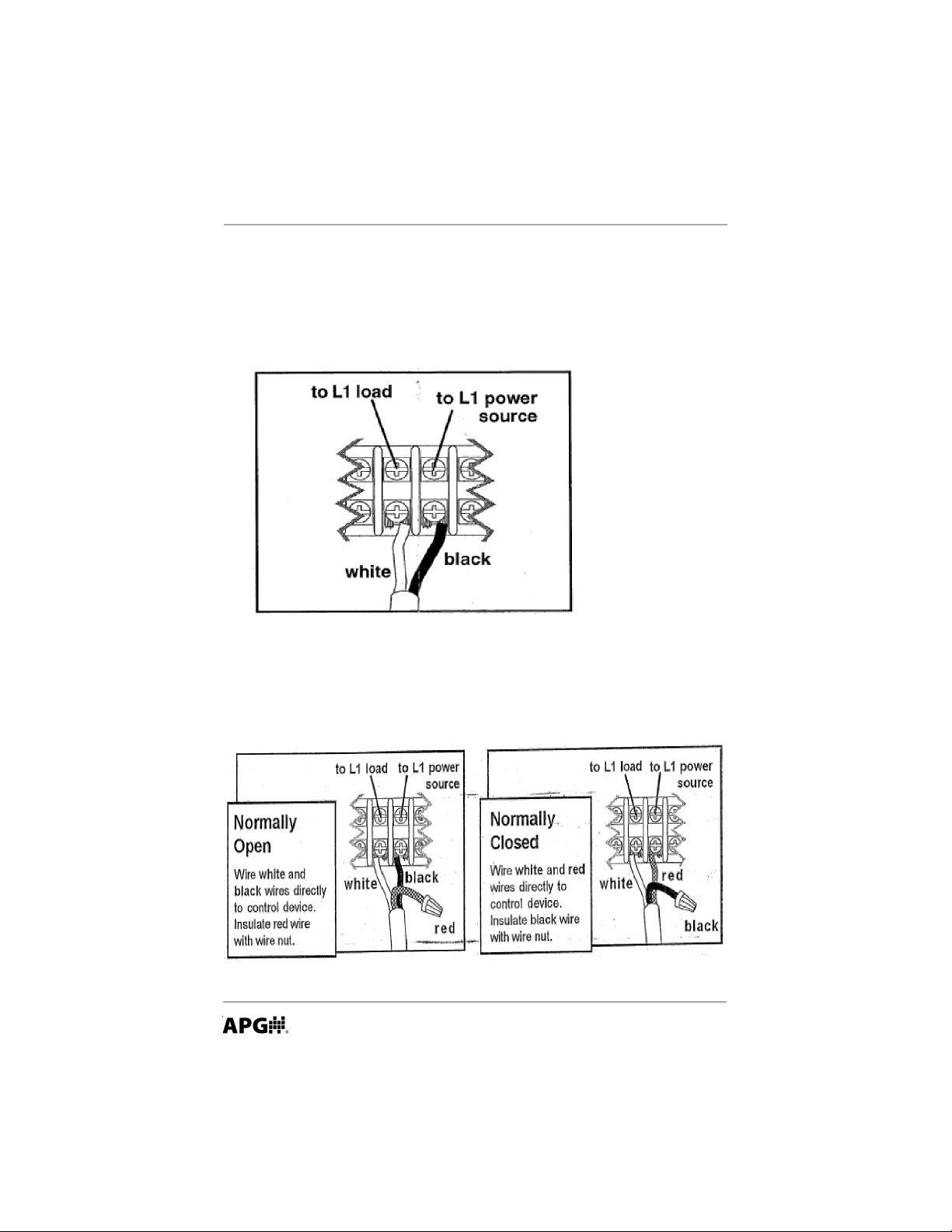
Wiring Diagrams
1. For the FT -100A or FT-100B connect cable leads directly into control device
as shown in Figure B.
Figure B
2. For the FT -100C connect cable leads directly into control device as shown
in Figure C.
Figure C
Automation Products Group, Inc.
6
APG...Providing tailored solutions for measurement applications
Tel: 1/888/525-7300 • Fax: 1/435/753-7490 • www .apgsensors.com • sales@apgsensors.com
Page 7

Rev. A3, 6/09 FT-100 Series
Cable Weight
1. Suspend switch and cable weight
at desired activation level as
shown in Figure D.
2. Connect cable leads directly into
control device as shown in
Figures B or C.
3. Check installation. Allow system
to cycle to ensure proper
operation.
To adjust cable weight:
1. Release clip.
2. Adjust cable weight to desired
position.
3. Lay switch cable in weight
channel.
4. Align clip with weight channel
and slide towards switch cable as
shown in Figure D.
5. Snap clip snugly up to cable,
moving clip to tightest possible
position.
Figure D
Automation Products Group, Inc.
APG...Providing tailored solutions for measurement applications
Tel: 1/888/525-7300 • Fax: 1/435/753-7490 • www .apgsensors.com • sales@apgsensors.com
7
Page 8

AUTOMATION
APG...Providing tailored solutions
for measurement applications
Automation Products Group, Inc.
T el: 1/888/525-7300
Fax: 1/435/753-7490
e-mail: sales@apgsensors.com
www.apgsensors.com
GROUP, INC.
1/435/753-7300
PRODUCTS
Automation Products Group, Inc.
1025 W. 1700 N.
Logan, UT 84321
 Loading...