

Page 1

PRODUCTS
AUTOMATION
Operator’s Manual
GROUP, INC.
FLE
Series
Magnetic Float Sensors
Rev. A3, 10/08
Doc. 9002273
APG...Providing tailored solutions for measurement applications
Tel: 1/888/525-7300 • Fax: 1/435/753-7490 • www .apgsensors.com • E-mail: sales@apgsensors.com
Automation Products Group, Inc.
Page 2

FLE Series Rev. A3, 10/08
Table of Contents
Warranty ......................................................................................... 3
Description...................................................................................... 4
Installation ................................................................................... 5-6
Wiring.............................................................................................. 7
Circuit Protection ........................................................................... 8
Inspection & Maintenance .............................................................. 9
Technical Notes............................................................................... 9
Specifications ................................................................................ 10
Automation Products Group, Inc.
2
APG...Providing tailored solutions for measurement applications
Tel: 1/888/525-7300 • Fax: 1/435/753-7490 • www.apgsensors.com • sales@apgsensors.com
Page 3

Rev. A3, 10/08 FLE Series
• Warranty and Warranty Restrictions
APG warrants its products to be free from defects of material and workmanship
and will, without charge, replace or repair any equipment found defective upon
inspection at its factory, provided the equipment has been returned,
transportation prepaid, within 24 months from date of shipment from factory .
THE FOREGOING WARRANTY IS IN LIEU OF AND EXCLUDES ALL OTHER
WARRANTIES NOT EXPRESSLY SET FORTH HEREIN, WHETHER
EXPRESSED OR IMPLIED BY OPERATION OF LAW OR OTHER WISE
INCLUDING BUT NOT LIMITED T O ANY IMPLIED WARRANTIES OF
MERCHANT ABILITY OR FITNESS FOR A P AR TICULAR PURPOSE.
No representation or warranty, express or implied, made by any sales
representative, distributor, or other agent or representative of APG which is not
specifically set forth herein shall be binding upon APG. APG shall not be liable
for any incidental or consequential damages, losses or expenses directly or
indirectly arising from the sale, handling, improper application or use of the
goods or from any other cause relating thereto and APG’s liability hereunder, in
any case, is expressly limited to the repair or replacement (at APG’s option) of
goods.
Warranty is specifically at the factory. Any on site service will be provided at
the sole expense of the Purchaser at standard field service rates.
All associated equipment must be protected by properly rated electronic/
electrical protection devices. APG shall not be liable for any damage due to
improper engineering or installation by the purchaser or third parties. Proper
installation, operation and maintenance of the product becomes the
responsibility of the user upon receipt of the product.
Returns and allowances must be authorized by APG in advance. APG will
assign a Return Material Authorization (RMA) number which must appear on
all related papers and the outside of the shipping carton. All returns are subject
to the final review by APG. Returns are subject to restocking charges as
determined by APG’s “Credit Return Policy”.
Automation Products Group, Inc.
APG...Providing tailored solutions for measurement applications
Tel: 1/888/525-7300 • Fax: 1/435/753-7490 • www .apgsensors.com • sales@apgsensors.com
3
Page 4
FLE Series Rev. A3, 10/08
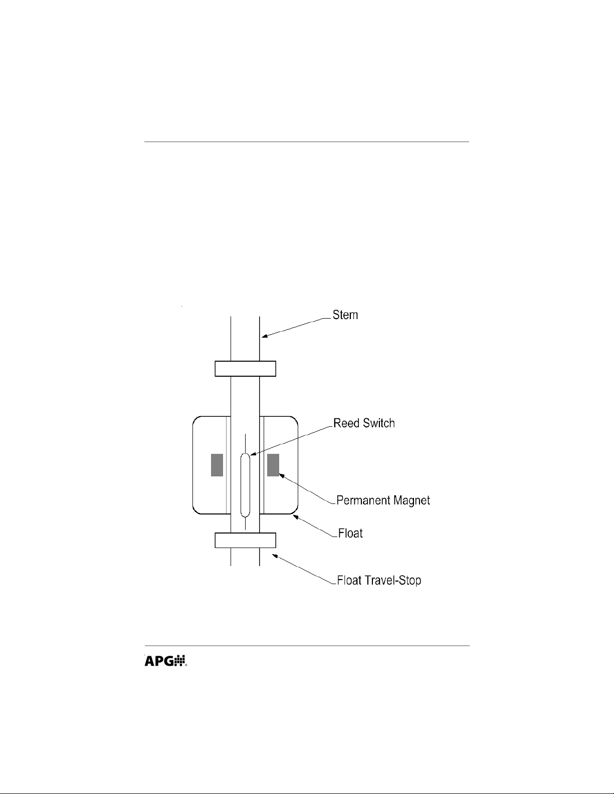
• Description
The FLE series instruments contain reed switches in the stem and permanent
magnets in the floats. As the float rises or falls with the level of the liquid, the
magnet inside the float act on the reed switch inside the stem to provide the
SPST switching action.
Automation Products Group, Inc.
4
APG...Providing tailored solutions for measurement applications
Tel: 1/888/525-7300 • Fax: 1/435/753-7490 • www.apgsensors.com • sales@apgsensors.com
Page 5

Rev. A3, 10/08 FLE Series
• Installation
- Unpacking -
When unpacking the instrument, exercise care not to subject the instrument to
mechanical shock. After unpacking, visually inspect the instrument for
damage.
- Environment -
The FLE series sensors should be installed in an area which meets the following
conditions:
1. Non-hazardous area.
2. The medium temperature does not exceed -140F to 1850F (-100C to 850C).
3. Locate the sensor away from strong magnetic fields such as those produced
by motors, transformers, solenoid valves, etc.
4. The medium is free from metallic substances and other foreign matter .
5. No corrosive gases such as NH3, SO2, Cl2, etc.
6. No excessive vibration
7. Ample space for maintenance and inspection.
Automation Products Group, Inc.
APG...Providing tailored solutions for measurement applications
Tel: 1/888/525-7300 • Fax: 1/435/753-7490 • www .apgsensors.com • sales@apgsensors.com
5
Page 6

FLE Series Rev. A3, 10/08
• Installation
- Location -
Do not locate the FLE series sensor near inlets/outlets.
If there is surface wave action, then use a time-delay relay or stilling tube. If a
stilling tube is used, drill vent holes in the tube and use a centering spacer on
the bottom of the stem to assure the float has free travel inside the tube.
Wave action may cause switch to chatter. Use a stilling tube or time-delay
relay to prevent switch chatter.
- Mounting -
The FLE can be mounted up to 300 from vertical.
1. Flange Mounting
Provide the compatible mating flange on the tank and install using a suitable
gasket.
2. Plug Mounting
Provide the compatible female boss on the tank and install the FLE with a
suitable gasket, O-ring, or thread tape.
Automation Products Group, Inc.
6
APG...Providing tailored solutions for measurement applications
Tel: 1/888/525-7300 • Fax: 1/435/753-7490 • www.apgsensors.com • sales@apgsensors.com
Page 7

Rev. A3, 10/08 FLE Series
• Wiring
- Wiring for 1 to 3 switches
Automation Products Group, Inc.
APG...Providing tailored solutions for measurement applications
Tel: 1/888/525-7300 • Fax: 1/435/753-7490 • www .apgsensors.com • sales@apgsensors.com
7
Page 8
FLE Series Rev. A3, 10/08
L
C
R
E
C = I
R = Approx.
10 x I (I + 50/E)
E
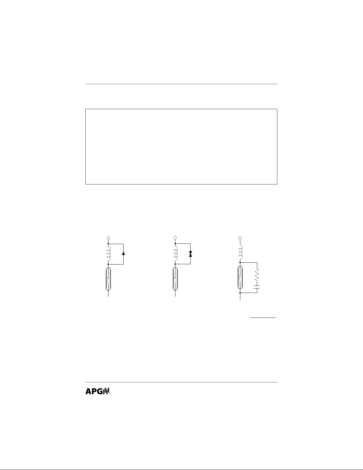
Protecting Circuit Using CRProtecting Circuit Using Varistor
Protecting Circuit Using Diode
2
/10 (uF)
• Circuit Protection
W ARNING!
DO NOT EXCEED CONT ACT RA TINGS! When an inductive load is
used (e.g. a motor, a coil, or an electromagnetic relay), a back
electromotive force of several hundred volts (energy stored in the
inductance) arises when the contacts are opened. This results in
considerable decrease in contact life. The same result arises even
when a resistive load is used with a high voltage or a large current. The
figures below show circuits for protecting the reed switch(s) from the
back electromotive force.
Switch Code A Code B
Max. contact capacity 20 VA 50 VA
Max. switching current 0.5A AC 0.5 A AC
Max. Voltage 220 VAC 220 VAC
Automation Products Group, Inc.
8
APG...Providing tailored solutions for measurement applications
Tel: 1/888/525-7300 • Fax: 1/435/753-7490 • www.apgsensors.com • sales@apgsensors.com
Page 9

Rev. A3, 10/08 FLE Series
• Inspection and Maintenance
Periodic inspection is necessary to keep your FLE unit in good working
order.
CAUTION! Do not remove the housing cover until the power
supplied to the unit is turned off.
Keep the sensor clean.
Never leave the housing cover off (for units equipted with a housing).
If the cover becomes damaged or is misplaced, order a replacement
immediately .
If sediment or other foreign matter is trapped between the stem
and the float, detection errors may be caused. Keep the float and
stem clean.
• Technical Notes
1. The float travel stop settings are based on how the magnetic field
influences the reed switch. Normally it is not necessary to move the
stop. If the stops are moved, check the switch action for float overrun.
2. Normally Open (NO) (switch closes as level rises) and Normally Closed
(NC) (switch closes as level falls).
Automation Products Group, Inc.
APG...Providing tailored solutions for measurement applications
Tel: 1/888/525-7300 • Fax: 1/435/753-7490 • www .apgsensors.com • sales@apgsensors.com
9
Page 10

FLE Series Rev. A3, 10/08
• FLE Specifications
Maximum Number Switching Points 3
Resolution +/- 1/16” (2mm)
Field Adjustable Actuation Levels No
Maximum Length 48 in.
Maximum Process Temperature -140 to 1850 F
(-100 to 850 C)
Housing Material (optional)
Aluminium (IP68, NEMA 4X),
St ainless S teel ((NEMA 4X)
Nylon (IP 65)
Hazardous Rating None
Contact Rating:
Switch Code A Code B
Max. contact capacity 20 VA 50 VA
Max. switching current 0.5A AC 0.5 A AC
Max. Voltage 220 VAC 220 VAC
Automation Products Group, Inc.
10
APG...Providing tailored solutions for measurement applications
Tel: 1/888/525-7300 • Fax: 1/435/753-7490 • www.apgsensors.com • sales@apgsensors.com
Page 11

Rev. A3, 10/08 FLE Series
Notes
Automation Products Group, Inc.
APG...Providing tailored solutions for measurement applications
Tel: 1/888/525-7300 • Fax: 1/435/753-7490 • www .apgsensors.com • sales@apgsensors.com
11
Page 12

AUTOMATION
APG...Providing tailored solutions
for measurement applications
Automation Products Group, Inc.
T el: 1/888/525-7300
Fax: 1/435/753-7490
e-mail: sales@apgsensors.com
www.apgsensors.com
GROUP, INC.
1/435/753-7300
PRODUCTS
Automation Products Group, Inc.
1025 W. 1700 N.
Logan, UT 84321
 Loading...