

Page 1

Automation Products Group
Modbus® Register Tables
Automation Products Group
1025 W 1700 N • Logan UT 84321 USA
Tel (435) 753-7300 • Fax (435) 753-7490
APG
www.apgsensors.com
®
Page 2

Automation Products Group Modbus® Register Tables Serial Communication
WARNING
As is typical with most instruments, the addition of serial communications carries an inherent risk; it allows a remote operator to change
the operation and/or characteristics of the device being digitally communicated with (in this case, the meter). Inappropriate
communication could have serious consequences in meter or system operation.
Ultimately, it is up to the system designer to provide for the safe operation of a process. But certainly, no single event should make the
difference between a safe situation and a catastrophe. Please use the appropriate level of caution when implementing serial
communication.
CAUTION: If the Interlock Relay function is being used on the meter, its proper operation can be affected by inappropriate digital
communications. Please take the steps necessary to provide for reliable interlock protection.
Disclaimer
The information contained in this document is subject to change without notice. Automation Products Group makes no representations
or warranties with respect to the contents hereof; and specifically disclaims any implied warranties of merchantability or fitness for a
particular purpose.
Register Trademarks
Modbus® is a Registered Trademark of Schneider Automation Inc. All other trademarks mentioned in this document are the property of
their respective owners.
© 2018 Automation Products Group, Inc. All rights reserved.
Page 2
Page 3

Automation Products Group Modbus® Register Tables Serial Communication
Introduction
This document describes how to communicate with the DDD, DBD, DDL, and DDX series of meters, with firmware version 3.200 & greater, using the Modbus® RTU Serial
Communication Protocol. The user should be familiar with Modbus serial communication and the meters. Refer to the meter instruction manual and the serial communication
adapters’ manual for setup and wiring instructions.
Go to http://www.modbus.org/ to obtain a copy of the Modbus Specifications and to find Modbus Technical Resources.
Note that although there are no specific 3x Registers, all 4x Registers are mirrored into 3x register space, and are therefore capable of being read by Modbus function 04
(Read Input Registers).
Register Overview
40001 – 40047: Process Value (PV), Max PV, Min PV, Total, and Grand Total in floating point and long integer formats, with interspersed relay status & digital I/O status, for block
reading; Start & Stop batch, Relay acknowledge, Reset Max & Min, Reset Total, Grand Total & Batch count.
40051 – 40089: Manual control of relays, analog output, and digital outputs; Modbus input display settings to use the meter as a Modbus display.
40101 – 40125: Input selection, Decimal points, totalizer settings, display settings, and display intensity.
40126 – 40145: Adjust, RTD number to average, Filter & Bypass, Gate settings for pulse input, Serial communication settings, Transfer function, Number of points, Exponent, Round
horizontal tank parameters, and Cutoff.
40171 – 40180: Passwords 1-3, Total & Grand Total Passwords.
40181 – 40187: Dual-scale model: PV2 settings and PV2 value, PV1 Percent.
40201 – 40220: Function keys & Digital I/O
40301 – 40372: Relays; Set & Reset points, Turn-on & Turn-off delays, Operating Mode.
40401 – 40413: Analog output value and setup parameters.
41001 – 41129: Remote Scaling for 4-20 mA input (Ch-A).
41201 – 41329: Remote Scaling for 4-20 mA input (Ch-B).
42001 – 42129: Remote Scaling for voltage input (Ch-A).
42201 – 42329: Remote Scaling for voltage input (Ch-B).
43001 – 43129: Remote Scaling for pulse input.
44001 – 44129: Remote Scaling for 4-20 mA input PV2 (Dual-scale, single input).
45001 – 45129: Remote Scaling for voltage input PV2 (Dual-scale, single input).
46001 – 46405: PV Channel B and additional dual-input parameters.
46201 – 46202: Channel C value (Math channel).
49901 – 49908: Product ID and Firmware Version.
49999: Load Factory Defaults
Page 3
Page 4
Automation Products Group Modbus® Register Tables Serial Communication
Register
Number
40001 – 40002
40003
40004
40005 – 40006
40007 – 40008
40009 – 40010
40011 – 40012
40013 – 40014
40015 – 40016
40017 – 40018
40019 – 40020
40021
40022
1
Address
(Hex)
0 – 1
(0000 – 0001)
2
(0002)
3
(0003)
4 – 5
(0004 – 0005)
6 – 7
(0006 – 0007)
8-9
(0008 – 0009)
10 – 11
(000A – 000B)
12 – 13
(000C – 000D)
14 – 15
(000E – 000F)
16 – 17
(0010 – 0011)
18 – 19
(0012 – 0013)
20
(0014)
21
(0015)
Name Access
PV/Rate Display
value
Alarm and Relay
status
Digital Inputs and
Outputs status
Maximum
Display value
Minimum Display
value
Total value Read Only 0 to 999999999 User defined Floating point 03, 04
Grand Total
value
Total overflow
value
Total non-
overflow value
Grand Total
overflow value
Grand Total non-
overflow value
PV/Rate Display
value
PV/Rate Display
value
Read Only
Read Only
Read Only
Read Only
Read Only
Read Only 0 to 999999999 User defined Floating point 03, 04
Read Only 0 to 999 User defined Floating point 03, 04
Read Only 0 to 999999 User defined Floating point 03, 04
Read Only 0 to 999 User defined Floating point 03, 04
Read Only 0 to 999999 User defined Floating point 03, 04
Read Only
Read Only User defined Long Lo 03, 04
Limits or
1 = In Alarm
energized
1 = Output active
Range
-99999 to
999999
1 = relay
1 = Input
selected
-99999 to
999999
-99999 to
999999
-99999 to
999999
2
Units
User defined Floating point 03, 04
None Word; Bits 03, 04
None Word; Bits 03, 04
User defined Floating point 03, 04
User defined Floating point 03, 04
User defined Long Hi 03, 04
Data
Type
3
Function
Code(s)
Comments
Represents the PV/Rate display value including the decimal point. Under
Range = -99999, Over Range = 999999, and
Open = -99999
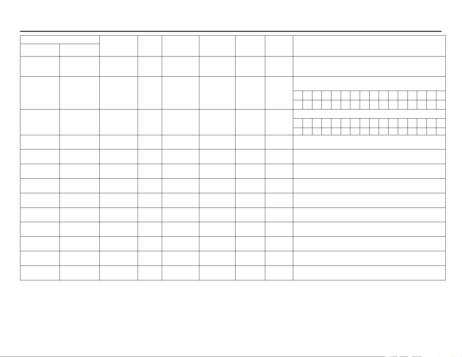
Read alarm status and energized/non-energized status of relays. Alm =
Alarm. Rly = Relay.
15 14 13 12 11 10 9 8 7 6 5 4 3 2 1 0
Alm8 Alm7 Alm6 Alm5 Alm4 Alm3 Alm2 Alm
Read the state of the digital inputs and outputs.
15 14 13 12 11 10 9 8 7 6 5 4 3 2 1 0
DI 8 DI 7 DI 6 DI 5 DI 4 DI 3 DI 2 DI 1 DO8 DO7 DO6 DO5 DO4 DO3 DO2 DO1
Represents the Maximum display value, including the decimal point,
since last power up or Max Value reset.
Represents the Minimum display value, including the decimal point,
since last power up or Min Value reset.
Represents the Total value, including the decimal point, since last Total
reset.
Represents the Grand Total value, including the decimal point, since last
Grand Total reset.
Represents the Total overflow value, since last Total reset.
Represents the Total non-overflow value, since last Total reset.
Represents the Grand Total overflow value, since last Grand Total reset.
Represents the Grand Total non-overflow value, since last Grand Total
reset.
Represents the PV/Rate display value excluding the decimal point.
Decimal point setting in 40102.
Must be read with 40021.
Rly8 Rly7 Rly6 Rly5 Rly4 Rly3 Rly2 Rly1
1
Page 4
Page 5
Automation Products Group Modbus® Register Tables Serial Communication
Number
40023
40024
40025
40026
40027
40028
40029
40030
40031
40032
40033
40034
40035
40036
40037
40038
40039
Register
1
Address
(Hex)
22
(0016)
23
(0017)
24
(0018)
25
(0019)
26
(001A)
27
(001B)
28
(001C)
29
(001D)
30
(001E)
31
(001F)
32
(0020)
33
(0021)
34
(0022)
35
(0023)
36
(0024)
37
(0025)
38
(0026)
Name Access
Alarm and Relay
status
Digital Inputs and
Outputs status
Maximum
Display value
Maximum
Display value
Minimum Display
value
Minimum Display
value
Total value Read Only 0 to 999999999 User defined Long Hi 03, 04
Total value Read Only User defined Long Lo 03, 04
Grand Total
value
Grand Total
value
Total overflow
value
Total non-
overflow value
Total non-
overflow value
Grand Total
overflow value
Grand Total non-
overflow value
Grand Total non-
overflow value
Start Batch Write Only Not applicable None Bit 06, 16
Read Only
Read Only
Read Only
Read Only User defined Long Lo 03, 04
Read Only
Read Only User defined Long Lo 03, 04
Read Only 0 to 999999999 User defined Long Hi 03, 04
Read Only User defined Long Lo 03, 04
Read Only 0 to 999 User defined Integer 03, 04
Read Only 0 to 999999 User defined Long Hi 03, 04
Read Only User defined Long Lo 03, 04
Read Only 0 to 999 User defined Integer 03, 04
Read Only 0 to 999999 User defined Long Hi 03, 04
Read Only User defined Long Lo 03, 04
Limits or
1 = In Alarm
energized
1 = Output active
Range
1 = relay
1 = Input
selected
-99999 to
999999
-99999 to
999999
2
Units
None Word; Bits 03, 04
None Word; Bits 03, 04
User defined Long Hi 03, 04
User defined Long Hi 03, 04
Data
Type
3
Function
Code(s)
Comments
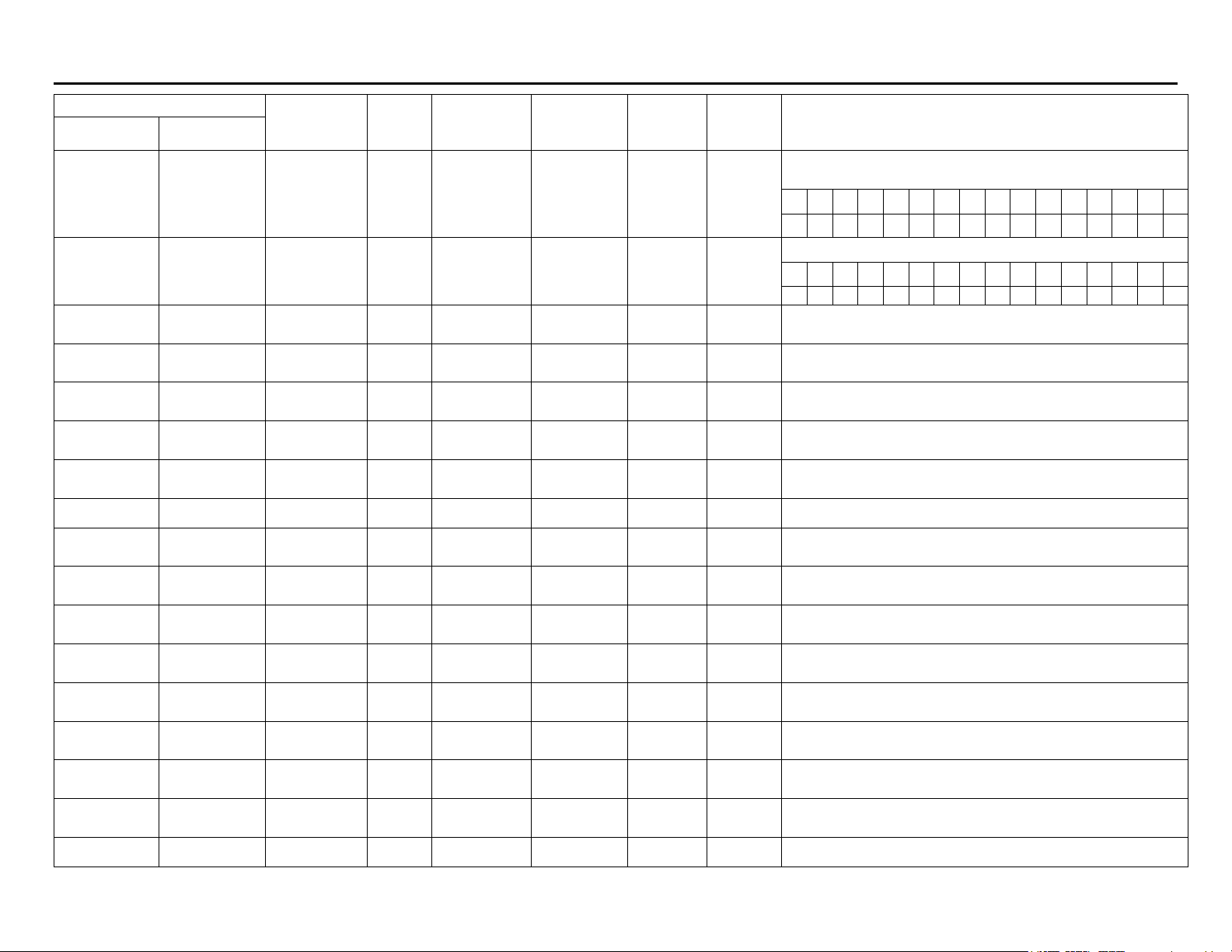
Mirror of 40003. Read alarm status and energized/non-energized status
of relays. Alm = Alarm. Rly = Relay.
15 14 13 12 11 10 9 8 7 6 5 4 3 2 1 0
Alm8Alm7Alm6Alm5Alm4Alm3Alm2Alm
Mirror of 40004. Read the state of the digital inputs and outputs.
15 14 13 12 11 10 9 8 7 6 5 4 3 2 1 0
DI 8 DI 7 DI 6 DI 5 DI 4 DI 3 DI 2 DI 1 DO8 DO7 DO6 DO5 DO4 DO3 DO2 DO1
Represents the Maximum display value, excluding the decimal point,
since last power up or Max Value reset.
Must be read with 40025.
Represents the Minimum display value, excluding the decimal point,
since last power up or Min Value reset.
Must be read with 40027.
Represents the Total value, excluding the decimal point, since last Total
reset. Decimal point setting in 40103.
Must be read with 40029.
Represents the Grand Total value, excluding the decimal point, since
last Total reset. Decimal point setting in 40104.
Must be read with 40031.
Represents the Total overflow value, since last Total reset.
Represents the Total non-overflow value, since last Total reset.
Must be read with 40034.
Represents the Grand Total overflow value, since last Grand Total reset.
Represents the Grand Total non-overflow value, since last Grand Total
reset.
Must be read with 40037.
Set bit to 1 to start the batch process.
Rly8 Rly7 Rly6 Rly5 Rly4 Rly3 Rly2 Rly1
1
Page 5
Page 6
Automation Products Group Modbus® Register Tables Serial Communication
Number
40040
40041
40042
40043
40044
40045
40046
Register
1
Address
(Hex)
39
(0027)
40
(0028)
41
(0029)
42
(002A)
43
(002B)
44
(002C)
45
(002D)
Name Access
Stop Batch
Alarm
Acknowledge
Reset Maximum
Display value
Reset Minimum
Display value
Reset
Max/Min Display
value
Reset Total value Write Only Not applicable None Bit 06, 16
Reset Grand
Total value
Read
Write
Write Only Not applicable None Word; Bits 06, 16
Write Only Not applicable None Bit 06, 16
Write Only Not applicable None Bit 06, 16
Write Only Not applicable None Bit 06, 16
Write Only Not applicable None Bit 06, 16
Limits or
Not applicable None Integer 06, 16
Range
2
Units
Data
Type
3
Function
Code(s)
Comments
Send 1 to pause the batch process; send 1 again to stop batch process.
Read Batch state: 1=Start, 2=Pause, 4=Stop, 8=Delay
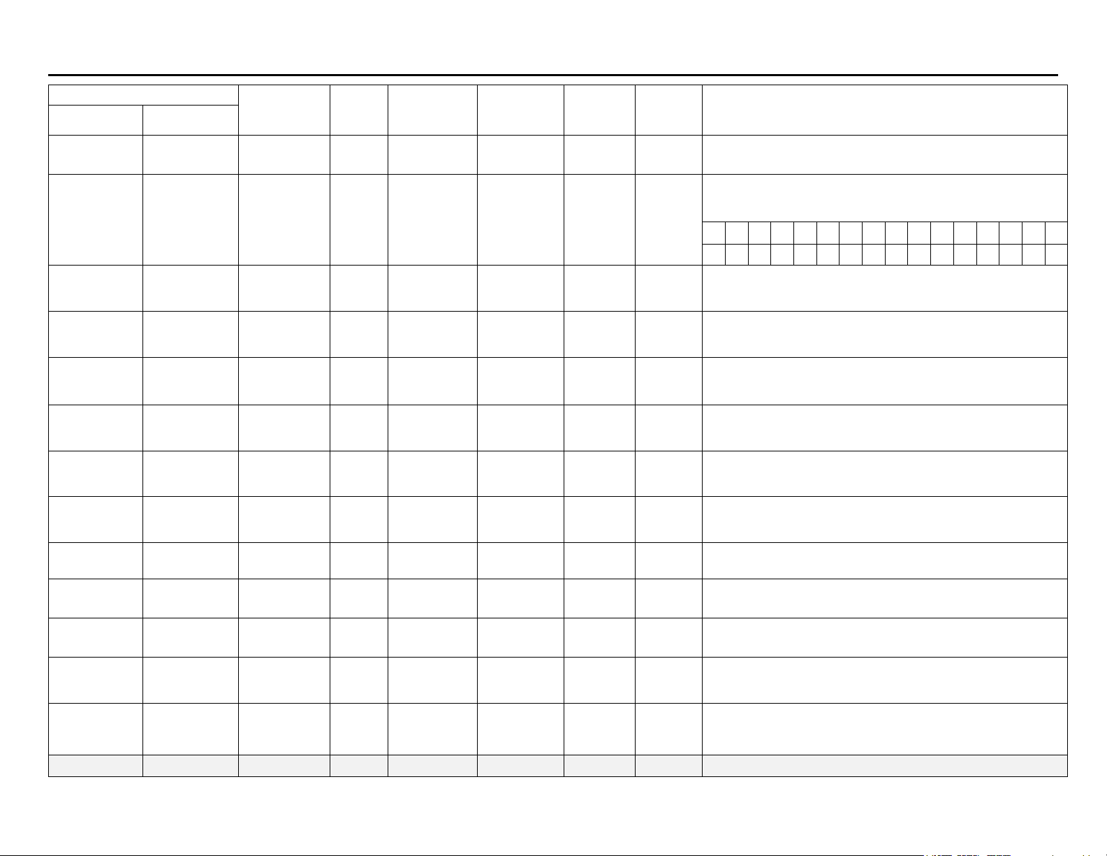
Clear Relay n alarm condition. Set bit equal to 1 to acknowledge. Only
has effect on relays programmed to allow manual acknowledging. Bits 07 mirror Bits 8-15, Alm = Alarm
15 14 13 12 11 10 9 8 7 6 5 4 3 2 1 0
Alm8Alm7Alm6Alm5Alm4Alm3Alm2Alm1Alm8Alm7Alm6Alm5Alm4Alm3Alm2 Alm
Set bit to 1 to reset the Maximum Display value.
Set bit to 1 to reset the Minimum Display value.
Set bit to 1 to reset the Maximum/ Minimum Display values.
Set bit to 1 to reset the Total value.
Set bit to 1 to reset the Grand Total value.
1
40047
40048
40049
40050
40051
40052
46
(002E)
47
(002F)
48
(0030)
49
(0031)
50
(0032)
51
(0033)
Reset Batch
Count value
Reset Tare Write Only Not applicable None Bit 06, 16
Tare Ch-A
Tare Ch-B
Control Mode
Manual Control
Analog Output
Setting
Write Only Not applicable None Bit 06, 16
Read
Write
Read
Write
Read
Write
Read
Write
Not applicable None Bit 06, 16
Not applicable None Bit 06, 16
Not applicable None Bit
0 to 23999 μA Integer
03, 04,
06, 16
03, 04,
06, 16
Set bit to 1 to reset the Batch Count value.
To read batch count use register 40152.
Set bit to 1 to reset or clear the tare.
Set bit to 1 to tare channel A
Read tare state: 0 = No Tare
Set bit to 1 to tare channel B
Read tare state: 0 = No Tare
0 = auto, 1 = manual
Represents the Manual Control Analog Output value.
Note: Register 40051 must be set to 1 = manual mode for registers
40052-40069 to take effect.
Page 6
Page 7

Automation Products Group Modbus® Register Tables Serial Communication
Number
40054
40055
40056
40057
40058
40059
40060
40061
40062
40063
40064
40065
40066
40067
40068
40069
40070
Register
1
Address
(Hex)
53
(0035)
54
(0036)
55
(0037)
56
(0038)
57
(0039)
58
(003A)
59
(003B)
60
(003C)
61
(003D)
62
(003E)
63
(003F)
64
(0040)
65
(0041)
66
(0042)
67
(0043)
68
(0044)
69
(0045)
Name Access
Manual Control
Relay 1 Setting
Manual Control
Relay 2 Setting
Manual Control
Relay 3 Setting
Manual Control
Relay 4 Setting
Manual Control
Relay 5 Setting
Manual Control
Relay 6 Setting
Manual Control
Relay 7 Setting
Manual Control
Relay 8 Setting
Manual Control
DO 1 Setting
Manual Control
DO 2 Setting
Manual Control
DO 3 Setting
Manual Control
DO 4 Setting
Manual Control
DO 5 Setting
Manual Control
DO 6 Setting
Manual Control
DO 7 Setting
Manual Control
DO 8 Setting
Modbus Big
Display Setting
Read
Write
Read
Write
Read
Write
Read
Write
Read
Write
Read
Write
Read
Write
Read
Write
Read
Write
Read
Write
Read
Write
Read
Write
Read
Write
Read
Write
Read
Write
Read
Write
Read
Write
Limits or
Not applicable None Bit
Not applicable None Bit
Not applicable None Bit
Not applicable None Bit
Not applicable None Bit
Not applicable None Bit
Not applicable None Bit
Not applicable None Bit
Not applicable None Bit
Not applicable None Bit
Not applicable None Bit
Not applicable None Bit
Not applicable None Bit
Not applicable None Bit
Not applicable None Bit
Not applicable None Bit
Not applicable None Bit
Range
2
Units
Data
Type
3
Function
Code(s)
03, 04,
06, 16
03, 04,
06, 16
03, 04,
06, 16
03, 04,
06, 16
03, 04,
06, 16
03, 04,
06, 16
03, 04,
06, 16
03, 04,
06, 16
03, 04,
06, 16
03, 04,
06, 16
03, 04,
06, 16
03, 04,
06, 16
03, 04,
06, 16
03, 04,
06, 16
03, 04,
06, 16
03, 04,
06, 16
03, 04,
06, 16
Comments
Represents the Manual Control Relay 1 setting. 0 = off, 1 = on
Represents the Manual Control Relay 2 setting. 0 = off, 1 = on
Represents the Manual Control Relay 3 setting. 0 = off, 1 = on
Represents the Manual Control Relay 4 setting. 0 = off, 1 = on
Represents the Manual Control Relay 5 setting. 0 = off, 1 = on
Represents the Manual Control Relay 6 setting. 0 = off, 1 = on
Represents the Manual Control Relay 7 setting. 0 = off, 1 = on
Represents the Manual Control Relay 8 setting. 0 = off, 1 = on
Represents the Manual Control Digital Output 1 setting. 0 = off, 1 = on
Represents the Manual Control Digital Output 2 setting. 0 = off, 1 = on
Represents the Manual Control Digital Output 3 setting. 0 = off, 1 = on
Represents the Manual Control Digital Output 4 setting. 0 = off, 1 = on
Represents the Manual Control Digital Output 5 setting. 0 = off, 1 = on
Represents the Manual Control Digital Output 6 setting. 0 = off, 1 = on
Represents the Manual Control Digital Output 7 setting. 0 = off, 1 = on
Represents the Manual Control Digital Output 8 setting. 0 = off, 1 = on
Represents the Modbus Big Display setting.
0 = display based on register 40072-40073.
1 = display based on register 40076-40081.
Modbus display mode must be set to 18 in register 40117.
Page 7
Page 8

Automation Products Group Modbus® Register Tables Serial Communication
Register
Number
40071
40072 – 40073
40074 – 40075
40076
40077
40078
40079
40080
40081
40082
40083
1
Address
(Hex)
70
(0046)
71 – 72
(0047 – 0048)
73 – 74
(0049 – 004A)
75
(004B)
76
(004C)
77
(004D)
78
(004E)
79
(004F)
80
(0050)
81
(0051)
82
(0052)
Name Access
Modbus Little
Display Setting
Modbus Big
Display value
Modbus Little
Display value
Modbus Big
Display MSD
value
Modbus Big
Display MSD-1
value
Modbus Big
Display MSD-2
value
Modbus Big
Display MSD-3
value
Modbus Big
Display MSD-4
value
Modbus Big
Display MSD-5
(LSD) value
Modbus Little
Display MSD
value
Modbus Little
Display MSD-1
value
Read
Write
Read
Write
Read
Write
Read
Write
Read
Write
Read
Write
Read
Write
Read
Write
Read
Write
Read
Write
Read
Write
Limits or
Not applicable None Bit
Not applicable None Byte
Not applicable None Byte
Not applicable None Byte
Not applicable None Byte
Not applicable None Byte
Not applicable None Byte
Not applicable None Byte
Not applicable None Byte
Range
-99999 to
+999999
-99999 to
+999999
2
Units
User defined
User defined
Data
Type
Long Hi
Long Lo
Long Hi
Long Lo
3
Function
Code(s)
03, 04,
06, 16
03, 04,
06, 16
03, 04,
06, 16
03, 04,
06, 16
03, 04,
06, 16
03, 04,
06, 16
03, 04,
06, 16
03, 04,
06, 16
03, 04,
06, 16
03, 04,
06, 16
03, 04,
06, 16
Comments
Represents the Modbus Little Display setting.
0 = display based on register 40074-40075.
1 = display based on register 40082-40087.
Modbus display mode must be set to 18 in register 40118.
Represents the Modbus Big display value excluding the decimal point.
Register 40088 contains the decimal point.
Set Register 40070 = 0, Register 40117 = 18
Represents the Modbus Little display value excluding the decimal point.
Register 40089 contains the decimal point.
Register 40071 = 0, Register 40118 = 18
Represents the Modbus Big Display MSD (Most Significant Digit) value.
The hex value represents the allowable ASCII character, see Table 8.
Register 40117 = 18
Register 40070 = 1 for registers 40076-81.
Register 40088 contains the decimal point.
Represents the Modbus Big Display MSD-1 value. The hex value
represents the allowable ASCII character.
Represents the Modbus Big Display MSD-2 value. The hex value
represents the allowable ASCII character.
Represents the Modbus Big Display MSD-3 value. The hex value
represents the allowable ASCII character.
Represents the Modbus Big Display MSD-4 value. The hex value
represents the allowable ASCII character.
Represents the Modbus Big Display MSD-5 (which is the LSD) value.
The hex value represents the allowable ASCII character.
Represents the Modbus Little Display MSD (Most Significant Digit) value.
The hex value represents the allowable ASCII character, see Table 8.
Register 40118 = 18
Register 40071 = 1 for registers 40082-87.
Register 40089 contains the decimal point.
Represents the Modbus Little Display MSD-1 value. The hex value
represents the allowable ASCII character.
Page 8
Page 9

Automation Products Group Modbus® Register Tables Serial Communication
Number
40084
40085
40086
40087
40088
40089
40090
Register
1
Address
(Hex)
83
(0053)
84
(0054)
85
(0055)
86
(0056)
87
(0057)
88
(0058)
89
(0059)
Name Access
Modbus Little
Display MSD-2
value
Modbus Little
Display MSD-3
value
Modbus Little
Display MSD-4
value
Modbus Little
Display MSD-5
(LSD) value
Modbus Big
Display decimal
point
Modbus Little
Display decimal
point
Level Meter
Read
Write
Read
Write
Read
Write
Read
Write
Read
Write
Read
Write
Read
Write
Limits or
Not applicable None Byte
Not applicable None Byte
Not applicable None Byte
Not applicable None Byte
Not applicable None Bit
2
Range
0 to 5 None Integer
0 to 5 None Integer
Units
Data
Type
3
Function
Code(s)
03, 04,
06, 16
03, 04,
06, 16
03, 04,
06, 16
03, 04,
06, 16
03, 04,
06, 16
03, 04,
06, 16
03, 04,
06, 16
Comments
Represents the Modbus Little Display MSD-2 value. The hex value
represents the allowable ASCII character.
Represents the Modbus Little Display MSD-3 value. The hex value
represents the allowable ASCII character.
Represents the Modbus Little Display MSD-4 value. The hex value
represents the allowable ASCII character.
Represents the Modbus Little Display MSD-5 (which is the LSD) value.
The hex value represents the allowable ASCII character.
Selects based on number of digits to the right of the decimal point (e.g. 0
= no decimal point and 5 = d.ddddd).
Register 40070 = 1 or 0
Selects based on number of digits to the right of the decimal point (e.g. 0
= no decimal point and 5 = d.ddddd).
Register 40071 = 1 or 0
Represents the selection for LEVEL meter with dual scale for PV1 and
PV2. 0 = No, 1 = Yes
40091
40092
90
(005A)
91
(005B)
Total
Mode
Scale/KFactor,
ICal/User Cal
selector
Read
Write
Read
Write
Not applicable None Bit
Not applicable None Bit
03, 04,
06, 16
03, 04,
06, 16
Represents the selection for Total.
For SFT039
0 = No, 1 = Yes
For SFT065
0 = None, 1 = Ch-A Total, 2 = Ch-B Total, 3 = Ch-A and Ch-B Total
For SFT039 (Single)
Most significant byte is used for mA selection.
Ical = 1, UserCal = 2, Scale = 4
Least significant byte is used for all other modes
Ical = 1, UserCal = 2, Scale = 4, KFactor = 8
For SFT065 (Single)
Most significant byte is used for Channel B selection.
Ical = 1, UserCal = 2, Scale = 4, KFactor = 8
Least significant byte is used for Channel A selection
Ical = 1, UserCal = 2, Scale = 4, KFactor = 8
Page 9
Page 10

Automation Products Group Modbus® Register Tables Serial Communication
Number
40093
40094
40095
40096
40097
Register
1
Address
(Hex)
92
(005C)
93
(005D)
94
(005E)
95
(005F)
96
(0031)
Name Access
Meter Model Read Only Not applicable None Integer
Relay & Digital
IO count
Meter Output Read Only Not applicable None Bit
Miscellaneous
Meter States
Zero Display
Read Only Not applicable None Word; bytes
Read Only Not applicable None Bit
Write
Only
Limits or
Not applicable None Bit 06, 16
Range
2
Units
Data
Type
3
Function
Code(s)
03, 04,
06, 16
03, 04,
06, 16
03, 04,
06, 16
03, 04,
06, 16
Comments
Hex Value LSB for non dual and
SFT 065 reg map revision 4
0 = Process/Temperature
1 = Process Total
2 = Pulse Total
3 = Dual-Input Process
4 = Reserve
5 = Process Batch
6 = Pulse Batch
7 = No Module
Hex Value MSB is Register Map
Revision
Relay & Digital IO count
LSByte = Relay count (4 or 8)
MSByte = Digital IO count (0, 4, or 8)
Represents the meter options
0 = None, 1 = Installed
Bit 0 = AOut Option,
Bit 1 = F4 option,
Bit 2 = Grand Total Non-Reset Password is set,
Bit 3 = Meter input open indication
Miscellaneous meter State Indications
Bit 0= Channel A or Single Channel Input Break fault
Bit 0= Channel B Input Break fault
Set bit to 1 to Zero display
Strain gauge meter only
Hex Value LSB for SFT 065 reg
map revision 0x20 and later
0 = Dual Process
1 = Dual Process Total
2 = Dual Pulse Total
3 = Dual Temperature
4 = Dual Process fixed VI
5 = Dual Process Batch
6 = Dual Pulse Batch
7 = No Module
40101
40102
40103
40104
100
(0064)
101
(0065)
102
(0066)
103
(0067)
Input Selection
PV/Rate decimal
point
Total decimal
point
Grand Total
decimal point
Read
Write
Read
Write
Read
Write
Read
Write
Not applicable None Word; bits
0 to 7 None Integer
0 to 5 None Integer
0 to 5 None Integer
03, 04,
06, 16
03, 04,
06, 16
03, 04,
06, 16
03, 04,
06, 16
See Table 1.
Selects based on number of digits to the right of the decimal point (e.g. 0
= no decimal point and 5 = d.ddddd), also selections for Temp Decimal
Point using 0 = dddd, 1 = dddd.d, 6 = dddd°u, and 7 = dddd.du, where
“u” is the units (F or C).
Selects based on number of digits to the right of the decimal point (e.g. 0
= no decimal point and 5 = d.ddddd).
Selects based on number of digits to the right of the decimal point (e.g. 0
= no decimal point and 5 = d.ddddd).
Page 10
Page 11

Automation Products Group Modbus® Register Tables Serial Communication
Register
Number
40105
40106 – 40107
40108
40109
40110
40111 – 40112
40113
40114
40115 – 40116
40117
40118
40119
40120
40121
40122
40123
40124
40125
1
Address
(Hex)
104
(0068)
105 – 106
(0069 – 006A)
107
(006B)
108
(006C)
109
(006D)
110 – 111
(006E – 006F)
112
(0070)
113
(0071)
114 – 115
(0072 – 0073)
116
(0074)
117
(0075)
118
(0076)
119
(0077)
120
(0078)
121
(0079)
122
(007A)
123
(007B)
124
(007C)
Name Access
Total time base
Total Conversion
Factor
Total Reset
mode
Total Reset
Delay
Grand Total time
base
Grand Total
Conversion
Factor
Grand Total
Reset mode
Grand Total
Reset Delay
Pulse K- Factor
Big Display
Setting
Little Display
Setting
Units 1
Units 2
Units 3
Units 4
Units 5
Units 6
Display Intensity
Read
Write
Read
Write
Read
Write
Read
Write
Read
Write
Read
Write
Read
Write
Read
Write
Read
Write
Read
Write
Read
Write
Read
Write
Read
Write
Read
Write
Read
Write
Read
Write
Read
Write
Read
Write
Limits or
0.00001 to
Not applicable None Bit
0.00001 to
Not applicable None Bit
0.00001 to
Not applicable None Byte
Not applicable None Byte
Not applicable None Byte
Not applicable None Byte
Not applicable None Byte
Not applicable None Byte
2
Range
999999
0 to 9999
999999
0 to 9999
999999
0 to 4 None Integer
0 to 4 None Integer
0 to 53 None Integer
0 to 53 None Integer
1 to 8 None Integer
Units
None Floating point
1/10 of Seconds
(0 to 999.9)
None Floating point
1/10 of Seconds
(0 to 999.9)
None Floating point
Data
Type
Integer
Integer
3
Function
Code(s)
03, 04,
06, 16
03, 04,
06, 16
03, 04,
06, 16
03, 04,
06, 16
03, 04,
06, 16
03, 04,
06, 16
03, 04,
06, 16
03, 04,
06, 16
03, 04,
06, 16
03, 04,
06, 16
03, 04,
06, 16
03, 04,
06, 16
03, 04,
06, 16
03, 04,
06, 16
03, 04,
06, 16
03, 04,
06, 16
03, 04,
06, 16
03, 04,
06, 16
Comments
0 = sec, 1 = min, 2 = hour, 3 = day
0 = auto, 1 = manual
0 = sec, 1 = min, 2 = hour, 3 = day
0 = auto, 1 = manual
See Table 2.
See Table 2.
Represents the Modbus Little Display MSD (Most Significant Digit) value.
The hex value represents the allowable ASCII character.
Represents the Modbus Little Display MSD-1 value. The hex value
represents the allowable ASCII character.
Represents the Modbus Little Display MSD-2 value. The hex value
represents the allowable ASCII character.
Represents the Modbus Little Display MSD-3 value. The hex value
represents the allowable ASCII character.
Represents the Modbus Little Display MSD-4 value. The hex value
represents the allowable ASCII character.
Represents the Modbus Little Display MSD-5 (which is the LSD) value.
The hex value represents the allowable ASCII character.
8 is the brightest level. Writing out of range data results in level 1 or 8.
Page 11
Page 12

Automation Products Group Modbus® Register Tables Serial Communication
Number
40126
40127
40128
40129
40130
40131
40132
40133
40134
40135
40136
40137
40138
Register
1
Address
(Hex)
125
(007D)
126
(007E)
127
(007F)
128
(0080)
129
(0081)
130
(0082)
131
(0083)
132
(0084)
133
(0085)
134
(0086)
135
(0087)
136
(0088)
137
(0089)
Name Access
Adjust Value
RTD Total Value
Lo Gate Setting
High Gate
Setting
Filter Setting
Bypass Setting
Serial Address
Serial Baud Rate
Serial Transmit
Delay
Serial Parity
Serial Byte-to-
Byte Timeout
Function Mode
PV/Rate mA
Number of Points
Read
Write
Read
Write
Read
Write
Read
Write
Read
Write
Read
Write
Read
Write
Read
Write
Read
Write
Read
Write
Read
Write
Read
Write
Read
Write
Limits or
-500 to 500 1/10 of °C or °F Integer
20 to 9999 None Integer
0, 2 to 199
202 to 250, 900
2
Range
1 to 999 None Integer
2 to 999
1 to 247 None Integer
0 to 199 ms Integer
0 to 254
1 to 10 None Integer
or
0 to 6 None Integer
0 to 3 None Integer
0 to 3 None Integer
2 to 32 None Integer
Units
Unit-less Integer
Percent of full
scale or °F
1/100 of
Seconds
Data
Type
Integer
Integer
3
Function
Code(s)
03, 04,
06, 16
03, 04,
06, 16
03, 04,
06, 16
03, 04,
06, 16
03, 04,
06, 16
03, 04,
06, 16
03, 04,
06, 16
03, 04,
06, 16
03, 04,
06, 16
03, 04,
06, 16
03, 04,
06, 16
03, 04,
06, 16
03, 04,
06, 16
Comments
Actually represents -50.0 to +50.0. Offset value is only applied to
temperature inputs. If Adjust is greater than 27.7°C and the temperature
units are switched to °F, it will be set to 50.0
(lower than -27.7, set to -50.0).
Value represents the number of parallel RTDs connected to the signal
input. Any other value than these results in a setting of 1.
Actually represents 0.1 to 99.9 setting.
Actually represents 2.0 to 999.9 setting.
Display filtering. 0 = no filtering. 2 to 199 = old + ((new - old)/Filter). For
pulse input 900 = Hi-Speed, 202 to 250 = Lo-Speed where the range is 2
to 50.
Actually represents 0.2 to 99.9. If the input steps greater than the bypass
value, it will be displayed immediately, with no filtering occurring. The
number represents percent of full-scale for process inputs and °F for
temperature inputs. No effect if filter = 0.
Changes to this register are saved but don’t take effect until next meter
reset (Modbus command or power-up). Writing out of range data results
in an address of 247.
0 = 300, 1 = 600, 2 = 1200, 3 = 2400, 4 = 4800, 5 = 9600, &
6 = 19200. Changes to this register are saved but don’t take effect until
next meter reset (Modbus command or power-up). Writing out of range
data results in a baud rate of 2400.
Transmit delay to minimize collisions on the RS-485 network.
0 = None with 1 stop bit, 1 = None with 2 stop bits, 2 = Odd,
3 = Even. Changes to this register are saved but don’t take effect until
next meter re-initialization (Writing 0xFF00 to 40299 or power-up).
Writing out of range data results in a parity setting of Even.
This is the timeout between bytes of a Modbus frame. Note that a value
less than the minimum value for the present baud rate cannot be saved.
Minimums are: 300 baud = 0.06 sec,
600 = 0.03, 1200 = 0.02 and 0.01 for 2400 to 19200. Changes to this
register are saved but don’t take effect until next meter reset (Modbus
command or power-up). Writing out of range data results in a timeout of
2.54 seconds.
0 = Linear, 1 = Square Root, 2 = Exponent,
3 = Round Horizontal Tank
This register is only used when register 40137 = 0 Linear.
Ch-A voltage input number of points uses register 40188.
Page 12
Page 13

Automation Products Group Modbus® Register Tables Serial Communication
Register
Number
40139
40140 – 40141
40142 – 40143
40144 – 40145
40146
40147 – 40148
40149
40150 – 40151
40152
40153
40154
40155
40156
40157
40158
1
Address
(Hex)
138
(008A)
139 – 140
(008B – 008C)
141 – 142
(008D – 008E)
143 – 144
(008F – 0090)
145
(0091)
146 – 147
(0092 – 0093)
148
(0094)
149 – 150
(0095 – 0096)
151
(0097)
152
(0098)
153
(99)
154
(9A)
155
(9B)
156
(9C)
157
(9D)
Name Access
Exponent
Round Horizontal
Tank Diameter
Round Horizontal
Tank Length
Cutoff
Batch Total
Count Direction
Batch Total
Preset
Grand Total
Count Direction
Grand Total
Count Down
Start
Batch Count Read Only 0 to 999999 None Integer
Dual Pulse
Quad Mode
Ch-A Total
Units 1
Ch- A Total
Units 2
Ch- A Total
Units 3
Ch- A Total
Units 4
Ch- A Total
Units 5
Read
Write
Read
Write
Read
Write
Read
Write
Read
Write
Read
Write
Read
Write
Read
Write
Read
Write
Read
Write
Read
Write
Read
Write
Read
Write
Read
Write
Limits or
10001 to 29999 None Integer
0 to 999.999 Inch/cm Floating point
0 to 999.999 Inch/cm Floating point
0 to 999999 User defined Floating point
Not applicable None Bit
0 to 999999999 User defined Floating point
Not applicable None Bit
0 to 999999999 User defined Floating point
Not applicable None Byte
Not applicable None Byte
Not applicable None Byte
Not applicable None Byte
Not applicable None Byte
2
Range
0 to 7 None Integer
Units
Type
Data
3
Function
Code(s)
03, 04,
06, 16
03, 04,
06, 16
03, 04,
06, 16
03, 04,
06, 16
03, 04,
06, 16
03, 04,
06, 16
03, 04,
06, 16
03, 04,
06, 16
03, 04,
06, 16
03, 04,
06, 16
03, 04,
06, 16
03, 04,
06, 16
03, 04,
06, 16
03, 04,
06, 16
03, 04,
06, 16
Comments
Actually represents 1.0001 to 2.9999.
Set register 40137 = 2
Decimal point is fixed. The unit of measure is inch or cm; the volume
calculation is in US gallon or liter. The display may be re-scaled to
represent the volume in any engineering units.
Register 40137 = 3 RHT
Register 40190 Round horizontal tank units
0 = inch Volume: Gallon
1 = cm Volume: Liter
Represents the cutoff value.
0 = count up, 1 = count down
Same as 40302 – 40303 Relay 1 set point.
0 = count up, 1 = count down
Represents the number of completed batches.
To reset the batch count use register 40047.
Dual Pulse Quad mode select
DUAL=0, UDAB=1, UDAI=2, UDBI=3, UDABI=4,
QUAD_1=5, QUAD_2=6, QUAD_4=7
Represents the Modbus Little Display MSD (Most Significant Digit) value.
The hex value represents the allowable ASCII character.
Represents the Modbus Little Display MSD-1 value. The hex value
represents the allowable ASCII character.
Represents the Modbus Little Display MSD-2 value. The hex value
represents the allowable ASCII character.
Represents the Modbus Little Display MSD-3 value. The hex value
represents the allowable ASCII character.
Represents the Modbus Little Display MSD-4 value. The hex value
represents the allowable ASCII character.
Page 13
Page 14

Automation Products Group Modbus® Register Tables Serial Communication
Register
Number
40159
40160
40161
40162
40163
40164
40165
40166 – 40167
40171 – 40172
40173 – 40174
40175 – 40176
40177 – 40178
40179 – 40180
40181
40182
1
Address
(Hex)
158
(9E)
159
(9F)
160
(A0)
161
(A1)
162
(A2)
163
(A3)
164
(A4)
166 – 167
(00A5 – 00A6)
170 – 171
(00AA-00AB)
172 – 173
(00AC-00AD)
174 – 175
(00AE-00AF)
176 – 177
(00B0 – 00B1)
178 – 179
(00B2 – 00B3)
180
(00B4)
181
(00B5)
Name Access
Ch- A Total
Units 6
Ch-A Grand Total
Units 1
Ch- A
Grand Total
Units 2
Ch- A
Grand Total
Units 3
Ch- A
Grand Total
Units 4
Ch- A
Grand Total
Units 5
Ch- A
Grand Total
Units 6
Total Count
Down Start
Password 1
Password 2
Password 3
Total Password
Grand Total
Password
PV2 Decimal
Point
PV2 mA
Number of Points
Read
Write
Read
Write
Read
Write
Read
Write
Read
Write
Read
Write
Read
Write
Read
Write
Read
Write
Read
Write
Read
Write
Read
Write
Read
Write
Read
Write
Read
Write
Limits or
Not applicable None Byte
Not applicable None Byte
Not applicable None Byte
Not applicable None Byte
Not applicable None Byte
Not applicable None Byte
Not applicable None Byte
0 to 999999999 User defined Floating point
000000 to
000000 to
000000 to
000000 to
000000 to
2
Range
999999
999999
999999
999999
999999
0 to 5 None Integer
2 to 8 None Integer
Units
None Floating point
None Floating point
None Floating point
None Floating point
None Floating point
Data
Type
3
Function
Code(s)
03, 04,
06, 16
03, 04,
06, 16
03, 04,
06, 16
03, 04,
06, 16
03, 04,
06, 16
03, 04,
06, 16
03, 04,
06, 16
03, 04,
06, 16
03, 04,
06, 16
03, 04,
06, 16
03, 04,
06, 16
03, 04,
06, 16
03, 04,
06, 16
03, 04,
06, 16
03, 04,
06, 16
Comments
Represents the Modbus Little Display MSD-5 (which is the LSD) value.
The hex value represents the allowable ASCII character.
Represents the Modbus Little Display MSD (Most Significant Digit) value.
The hex value represents the allowable ASCII character.
Represents the Modbus Little Display MSD-1 value. The hex value
represents the allowable ASCII character.
Represents the Modbus Little Display MSD-2 value. The hex value
represents the allowable ASCII character.
Represents the Modbus Little Display MSD-3 value. The hex value
represents the allowable ASCII character.
Represents the Modbus Little Display MSD-4 value. The hex value
represents the allowable ASCII character.
Represents the Modbus Little Display MSD-5 (which is the LSD) value.
The hex value represents the allowable ASCII character.
See Note 4.
See Note 4.
See Note 4.
See Note 4.
See Note 4.
Selects based on number of digits to the right of the decimal point (e.g. 0
= no decimal point and 5 = d.ddddd).
This register is only used when register 40137 is set to Linear.
PV2 voltage input uses register 40189.
Page 14
Page 15

Automation Products Group Modbus® Register Tables Serial Communication
Register
Number
40183 – 40184
40185
40186
40187
40188
40189
40190
40191 – 40192
40193
40194 – 40195
40196
40197
40198
40201
1
Address
(Hex)
182 – 183
(00B6 – 00B7)
184
(00B8)
185
(00B9)
186
(00BA)
187
(00BB)
188
(00BC)
189
(00BD)
190 – 191
(00BE – 00BF)
192
(00C0)
193 – 194
(00C1 – 00C2)
195
(00C3)
196
(00C4)
197
(00C5)
200
(00C8)
Name Access
PV2 Display
Value
PV2 Display
value
PV2 Display
value
PV1% Display
value
PV/Rate Volt
Number of Points
PV2 Volt
Number of Points
RHT Inch/cm
Selection
Programmed
Tare Value
Tare mode
Auto Zero
Threshold
Auto Zero
On/Off
Strain
Unipolar/Bipolar
select
Feet/Inch
1/8 or 1/16
resolution
Programmable
User F1 Setting
Limits or
Read Only
Read Only
Read Only User defined Long Lo 03, 04
Read Only -100 to 100 User defined Integer 03, 04
Read
Write
Read
Write
Read
Write
Read
Write
Read
Write
Read
Write
Read
Write
Read
Write
Read
Write
Read
Write
0 to 999999 User defined Floating point
Not applicable None Integer
2
Range
-99999 to
999999
-99999 to
999999
0 to 9.99 User defined Floating point
2 to 32 None Integer
2 to 8 None Integer
0 or 1 Inch or cm Integer
0 to 1 None Bit
0 to 1 None Bit
0 to 1 None Bit
0 to 71 User defined Integer
Units
User defined Floating point 03, 04
User defined Long Hi 03, 04
Data
Type
3
Function
Code(s)
03, 04,
06, 16
03, 04,
06, 16
03, 04,
06, 16
03, 04,
06,16
03, 04,
06, 16
03, 04,
06,16
03, 04,
06, 16
03, 04,
06, 16
03, 04,
06, 16
03, 04,
06, 16
Comments
Represents the PV2 display value including the decimal point. Under
Range = -99999, Over Range = 999999, and
Open = -99999
Represents the display value excluding the decimal point. Decimal point
setting in 40181.
Must be read with 40185.
Represents the PV1% display value.
This register is only used when register 40137 = 0 Linear.
Ch-A mA input number of points uses register 40138.
This register is only used when register 40137 = 0 Linear.
PV2 mA input uses register 40182.
Round horizontal tank engineering units
0 = inch Volume: Gallon
1 = cm Volume: Liter
This register is only used when register 40137 = 3 RHT.
Tank diameter and length: Registers 40140-143.
Programmed tare value. Must have Tare Programmed (40193) flag set
to take effect
0 = Tare off
1 = Use Capture Tare
2 = Use Programmed Tare
Auto Zero Threshold
Full scale times this value is the threshold of the input difference below
which Auto Zero is calculated
0 = Auto Zero Off
1 = Auto Zero On
0 = Unipolar
1 = Bipolar
th
0 = 1/8
th
1 = 1/16
See Table 3.
Page 15
Page 16

Automation Products Group Modbus® Register Tables Serial Communication
Number
40202
40203
40204
40205
40206
40207
40208
40209
40210
40211
40212
40213
40214
40215
Register
1
Address
(Hex)
201
(00C9)
202
(00CA)
203
(00CB)
204
(00CC)
205
(00CD)
206
(00CE)
207
(00CF)
208
(00D0)
209
(00D1)
210
(00D2)
211
(00D3)
212
(00D4)
213
(00D5)
214
(00D6)
Name Access
Programmable
User F2 Setting
Programmable
User F3 Setting
Programmable
User F4 Setting
Programmable
User Digital
Input 1 Setting
Programmable
User Digital
Input 2 Setting
Programmable
User Digital
Input 3 Setting
Programmable
User Digital
Input 4 Setting
Programmable
User Digital
Input 5 Setting
Programmable
User Digital
Input 6 Setting
Programmable
User Digital
Input 7 Setting
Programmable
User Digital
Input 8 Setting
Programmable
User Digital
Output 1 Setting
Programmable
User Digital
Output 2 Setting
Programmable
User Digital
Output 3 Setting
Read
Write
Read
Write
Read
Write
Read
Write
Read
Write
Read
Write
Read
Write
Read
Write
Read
Write
Read
Write
Read
Write
Read
Write
Read
Write
Read
Write
Limits or
2
Range
0 to 71 User defined Integer
0 to 71 User defined Integer
0 to 71 User defined Integer
0 to 71 User defined Integer
0 to 71 User defined Integer
0 to 71 User defined Integer
0 to 71 User defined Integer
0 to 71 User defined Integer
0 to 71 User defined Integer
0 to 71 User defined Integer
0 to 71 User defined Integer
0 to 38 User defined Integer
0 to 38 User defined Integer
0 to 38 User defined Integer
Units
Data
Type
3
Function
Code(s)
03, 04,
06, 16
03, 04,
06, 16
03, 04,
06, 16
03, 04,
06, 16
03, 04,
06, 16
03, 04,
06, 16
03, 04,
06, 16
03, 04,
06, 16
03, 04,
06, 16
03, 04,
06, 16
03, 04,
06, 16
03, 04,
06, 16
03, 04,
06, 16
03, 04,
06, 16
Comments
See Table 3.
See Table 3.
See Table 3.
See Table 3.
See Table 3.
See Table 3.
See Table 3.
See Table 3.
See Table 3.
See Table 3.
See Table 3.
See Table 3.
See Table 3.
See Table 3.
Page 16
Page 17

Automation Products Group Modbus® Register Tables Serial Communication
Register
Number
40216
40217
40218
40219
40220
40221
40222
40223 – 40224
40225 – 40226
40227 – 40228
40229
40230
40231
40232
40233
40234
1
Address
(Hex)
215
(00D7)
216
(00D8)
217
(00D9)
218
(00DA)
219
(00DB)
220
(00DC)
221
(00DD)
222 – 223
(00DE – 00DF)
224 – 225
(00E0 – 00E1)
226 – 227
(00E2 – 00E3)
228
(00E5)
229
(00E6)
230
(00E7)
231
(00E8)
232
(00E9)
233
(00EA)
Name Access
Programmable
User Digital
Output 4 Setting
Programmable
User Digital
Output 5 Setting
Programmable
User Digital
Output 6 Setting
Programmable
User Digital
Output 7 Setting
Programmable
User Digital
Output 8 Setting
Rounding
Units Code
Gross Display
Value
Net Display
Value
Millivolt Display
Value
Custom Units 1
Custom Units 2
Custom Units 3
Custom Units 4
Custom Units 5
Custom Units 6
Read
Write
Read
Write
Read
Write
Read
Write
Read
Write
Read
Write
Read
Write
Read Only
Read Only
Read Only
Read
Write
Read
Write
Read
Write
Read
Write
Read
Write
Read
Write
Limits or
Not applicable None Integer
Not applicable None
Not applicable None Byte
Not applicable None Byte
Not applicable None Byte
Not applicable None Byte
Not applicable None Byte
Not applicable None Byte
2
Range
-99999 to
999999
-99999 to
999999
-99999 to
999999
0 to 38 User defined Integer
0 to 38 User defined Integer
0 to 38 User defined Integer
0 to 38 User defined Integer
0 to 38 User defined Integer
Units
User defined Floating point 03, 04
User defined Floating point 03, 04
User defined Floating point 03, 04
Data
Type
3
Function
Code(s)
03, 04,
06, 16
03, 04,
06, 16
03, 04,
06, 16
03, 04,
06, 16
03, 04,
06, 16
03, 04,
06, 16
03, 04,
06, 16
03, 04,
06, 16
03, 04,
06, 16
03, 04,
06, 16
03, 04,
06, 16
03, 04,
06, 16
03, 04,
06, 16
Comments
See Table 3.
See Table 3.
See Table 3.
See Table 3.
See Table 3.
Display Rounding
Acceptable Index values are:
0=1, 1=2, 2=5, 3=10, 4=20, 5=50, and 6=100
This sets the meter units as follows:
0 = LB, 1= kG, 2 = Ounce, 3 = grams, 4 = Ton, 5 = Metric Ton,
6 = Custom. Custom is specified in reg 40119 thru 40124
Represents the Gross display value including the decimal point. Under
Range = -99999, Over Range = 999999
Represents the Net display value including the decimal point. Under
Range = -99999, Over Range = 999999
Represents the Net display value including the decimal point. Under
Range = -210.00, Over Range = 210.00
Represents the Custom Units Little Display MSD (Most Significant Digit)
value. The hex value represents the allowable ASCII character.
Represents the Custom Units Little Display MSD-1 value. The hex value
represents the allowable ASCII character.
Represents the Custom Units Little Display MSD-2 value. The hex value
represents the allowable ASCII character.
Represents the Custom Units Little Display MSD-3 value. The hex value
represents the allowable ASCII character.
Represents the Custom Units Little Display MSD-4 value. The hex value
represents the allowable ASCII character.
Represents the Custom Units Little Display MSD-5 value. The hex value
represents the allowable ASCII character.
Page 17
Page 18

Automation Products Group Modbus® Register Tables Serial Communication
Register
Number
40301
40302 – 40303
40304 – 40305
40306
40307
40308 – 40309
40310
40311 – 40312
40313 – 40314
40315
40316
40317 – 40318
40319
40320 – 40321
40322 – 40323
40324
40325
40326 – 40327
40328
1
Address
(Hex)
300
(012C)
301 – 302
(012D – 012E)
303 – 304
(012F – 0130)
305
(0131)
306
(0132)
307 – 308
(0133 – 0134)
309
(0135)
310 – 311
(0136 – 0137)
312 – 313
(0138 – 0139)
314
(013A)
315
(013B)
316 – 317
(013C – 013D)
318
(013E)
319 – 320
(013F – 0140)
321 – 322
(0141 – 0142)
323
(0143)
324
(0144)
325 – 326
(0145 – 0146)
327
(0147)
Name Access
Relay 1 Mode
Relay 1
Set Point
Relay 1
Reset Point
Relay 1
On Delay
Relay 1
Off Delay
Relay 1 Sample
Time
Relay 2 Mode
Relay 2
Set Point
Relay 2
Reset Point
Relay 2
On Delay
Relay 2
Off Delay
Relay 2 Sample
Time
Relay 3 Mode
Relay 3
Set Point
Relay 3
Reset Point
Relay 3
On Delay
Relay 3
Off Delay
Relay 3 Sample
Time
Relay 4 Mode
Read
Write
Read
Write
Read
Write
Read
Write
Read
Write
Read
Write
Read
Write
Read
Write
Read
Write
Read
Write
Read
Write
Read
Write
Read
Write
Read
Write
Read
Write
Read
Write
Read
Write
Read
Write
Read
Write
Limits or
Not applicable None Word; bits
0 to 59999 1/10 of Seconds Floating point
Not applicable None Word; bits
0 to 59999 1/10 of Seconds Floating point
Not applicable None Word; bits
0 to 59999 1/10 of Seconds Floating point
Not applicable None Word; bits
2
Range
-99999 to
999999
-99999 to
999999
0 to 1999 1/10 of Seconds Integer
0 to 1999 1/10 of Seconds Integer
-99999 to
999999
-99999 to
999999
0 to 1999 1/10 of Seconds Integer
0 to 1999 1/10 of Seconds Integer
-99999 to
999999
-99999 to
999999
0 to 1999 1/10 of Seconds Integer
0 to 1999 1/10 of Seconds Integer
Units
User defined Floating point
User defined Floating point
User defined Floating point
User defined Floating point
User defined Floating point
User defined Floating point
Data
Type
3
Function
Code(s)
03, 04,
06, 16
03, 04,
06, 16
03, 04,
06, 16
03, 04,
06, 16
03, 04,
06, 16
03, 04,
06, 16
03, 04,
06, 16
03, 04,
06, 16
03, 04,
06, 16
03, 04,
06, 16
03, 04,
06, 16
03, 04,
06, 16
03, 04,
06, 16
03, 04,
06, 16
03, 04,
06, 16
03, 04,
06, 16
03, 04,
06, 16
03, 04,
06, 16
03, 04,
06, 16
Comments
See Table 4 for operating modes and bit assignments.
See Table 4 for operating modes and bit assignments.
See Table 4 for operating modes and bit assignments.
See Table 4 for operating modes and bit assignments.
Page 18
Page 19

Automation Products Group Modbus® Register Tables Serial Communication
Register
Number
40329 – 40330
40331 – 40332
40333
40334
40335 – 40336
40337
40338 – 40339
40340 – 40341
40342
40343
40344 – 40345
40346
40347 – 40348
40349 – 40350
40351
40352
40353 – 40354
40355
40356 – 40357
1
Address
(Hex)
328 – 329
(0148 – 0149)
330 – 331
(014A – 014B)
332
(014C)
333
(014D)
334 – 335
(014E – 014F)
336
(0150)
337 – 338
(0151 – 0152)
339 – 340
(0153 – 0154)
341
(0155)
342
(0156)
343 – 344
(0157 – 0158)
345
(0159)
346 – 347
(015A – 015B)
348 – 349
(015C – 015D)
350
(015E)
351
(015F)
352 – 353
(0160 – 0161)
354
(0162)
355 – 356
(0163 – 0164)
Name Access
Relay 4
Set Point
Relay 4
Reset Point
Relay 4
On Delay
Relay 4
Off Delay
Relay 4 Sample
Time
Relay 5 Mode
Relay 5
Set Point
Relay 5
Reset Point
Relay 5
On Delay
Relay 5
Off Delay
Relay 5 Sample
Time
Relay 6 Mode
Relay 6
Set Point
Relay 6
Reset Point
Relay 6
On Delay
Relay 6
Off Delay
Relay 6 Sample
Time
Relay 7 Mode
Relay 7
Set Point
Read
Write
Read
Write
Read
Write
Read
Write
Read
Write
Read
Write
Read
Write
Read
Write
Read
Write
Read
Write
Read
Write
Read
Write
Read
Write
Read
Write
Read
Write
Read
Write
Read
Write
Read
Write
Read
Write
Limits or
0 to 59999 1/10 of Seconds Floating point
Not applicable None Word; bits
0 to 59999 1/10 of Seconds Floating point
Not applicable None Word; bits
0 to 59999 1/10 of Seconds Floating point
Not applicable None Word; bits
2
Range
-99999 to
999999
-99999 to
999999
0 to 1999 1/10 of Seconds Integer
0 to 1999 1/10 of Seconds Integer
-99999 to
999999
-99999 to
999999
0 to 1999 1/10 of Seconds Integer
0 to 1999 1/10 of Seconds Integer
-99999 to
999999
-99999 to
999999
0 to 1999 1/10 of Seconds Integer
0 to 1999 1/10 of Seconds Integer
-99999 to
999999
Units
User defined Floating point
User defined Floating point
User defined Floating point
User defined Floating point
User defined Floating point
User defined Floating point
User defined Floating point
Data
Type
3
Function
Code(s)
03, 04,
06, 16
03, 04,
06, 16
03, 04,
06, 16
03, 04,
06, 16
03, 04,
06, 16
03, 04,
06, 16
03, 04,
06, 16
03, 04,
06, 16
03, 04,
06, 16
03, 04,
06, 16
03, 04,
06, 16
03, 04,
06, 16
03, 04,
06, 16
03, 04,
06, 16
03, 04,
06, 16
03, 04,
06, 16
03, 04,
06, 16
03, 04,
06, 16
03, 04,
06, 16
Comments
See Table 4 for operating modes and bit assignments.
See Table 4 for operating modes and bit assignments.
See Table 4 for operating modes and bit assignments.
Page 19
Page 20

Automation Products Group Modbus® Register Tables Serial Communication
Register
Number
40358 – 40359
40360
40361
40362 – 40363
40364
40365 – 40366
40367 – 40368
40369
40370
40371 – 40372
40373 – 40374
40375 – 40376
40377 – 40378
40379 – 40380
40381 – 40382
40383 – 40384
40385 – 40386
40401
1
Address
(Hex)
357 – 358
(0165 – 0166)
359
(0167)
360
(0168)
361 – 362
(0169 – 016A)
363
(016B)
364 – 365
(016C – 016D)
366 – 367
(016E – 016F)
368
(0170)
369
(0171)
370 – 371
(0172 – 0173)
372 – 373
(0174 – 0175)
374 – 375
(0176 – 0177)
376 – 377
(0178 – 0179)
378 – 379
(017A – 017B)
380 – 381
(017C – 017D)
382 – 383
(017E – 017F)
384 – 385
(0180 – 0181)
400
(0190)
Name Access
Relay 7
Reset Point
Relay 7
On Delay
Relay 7
Off Delay
Relay 7 Sample
Time
Relay 8 Mode
Relay 8
Set Point
Relay 8
Reset Point
Relay 8
On Delay
Relay 8
Off Delay
Relay 8 Sample
Time
Relay 2
Pre-close Value
Relay 3
Pre-close Value
Relay 4
Pre-close Value
Relay 5
Pre-close Value
Relay 6
Pre-close Value
Relay 7
Pre-close Value
Relay 8
Pre-close Value
Analog Output
Value
Limits or
Read
Write
Read
Write
Read
Write
Read
Write
Read
Write
Read
Write
Read
Write
Read
Write
Read
Write
Read
Write
Read
Write
Read
Write
Read
Write
Read
Write
Read
Write
Read
Write
Read
Write
Read Only 1 to 23000 μA Integer 03, 04
0 to 59999 1/10 of Seconds Floating point
Not applicable None Word; bits
0 to 59999 1/10 of Seconds Floating point
0 to 999999 User define Floating point
0 to 999999 User define Floating point
0 to 999999 User define Floating point
0 to 999999 User define Floating point
0 to 999999 User define Floating point
0 to 999999 User define Floating point
0 to 999999 User define Floating point
2
Range
-99999 to
999999
0 to 1999 1/10 of Seconds Integer
0 to 1999 1/10 of Seconds Integer
-99999 to
999999
-99999 to
999999
0 to 1999 1/10 of Seconds Integer
0 to 1999 1/10 of Seconds Integer
Units
User defined Floating point
User defined Floating point
User defined Floating point
Data
Type
3
Function
Code(s)
03, 04,
06, 16
03, 04,
06, 16
03, 04,
06, 16
03, 04,
06, 16
03, 04,
06, 16
03, 04,
06, 16
03, 04,
06, 16
03, 04,
06, 16
03, 04,
06, 16
03, 04,
06, 16
03, 04,
06, 16
03, 04,
06, 16
03, 04,
06, 16
03, 04,
06, 16
03, 04,
06, 16
03, 04,
06, 16
03, 04,
06, 16
Comments
See Table 4 for operating modes and bit assignments.
See Table 4 for operating modes and bit assignments.
Page 20
Page 21

Automation Products Group Modbus® Register Tables Serial Communication
Register
Number
40402
40403
40404
40405
40406
40407
40408 – 40409
40410 – 40411
40412
40413
1
Address
(Hex)
401
(0191)
402
(0192)
403
(0193)
404
(0194)
405
(0195)
406
(0196)
407 – 408
(0197 – 0198)
409 – 410
(0199 – 019A)
411
(019B)
412
(019C)
Name Access
Analog Output
Source
Analog Output
Overrange value
Analog Output
Underrange
value
Analog Output
Sensor Break
value
Analog Output
Maximum value
allowed
Analog Output
Minimum value
allowed
Analog Output
Display Value 1
Analog Output
Display Value 2
Analog Output
Output 1
Analog Output
Output 2
Read
Write
Read
Write
Read
Write
Read
Write
Read
Write
Read
Write
Read
Write
Read
Write
Read
Write
Read
Write
Limits or
1 to 23000 μA Integer
1 to 23000 μA Integer
1 to 23000
1 to 23000 μA Integer
1 to 23000 μA Integer
1 to 23000 μA Integer
1 to 23000 μA Integer
2
Range
or 32000
-99999 to
999999
-99999 to
999999
0 to 21 None Integer
Units
μA Integer
User defined Floating point
User defined Floating point
Data
Type
3
Function
Code(s)
03, 04,
06, 16
03, 04,
06, 16
03, 04,
06, 16
03, 04,
06, 16
03, 04,
06, 16
03, 04,
06, 16
03, 04,
06, 16
03, 04,
06, 16
03, 04,
06, 16
03, 04,
06, 16
Comments
See Table 5 for selection of the 4-20mA output source.
This is analog channel “AOut_1” when multiple outputs are available
This is analog channel “AOut_1” when multiple outputs are available.
Write 32000 to ignore sensor break
Analog Output scaling is only saved to memory after receiving the
Output 2 – register 40413.
This is analog channel “AOut_1” when multiple outputs are available
DO NOT interleave channels when scaling AOut
40418
40422
40423
417
(01A1)
421
(01A5)
422
(01A6)
Analog Output
channel Number
Analog Output
Channel AOut_2
Source
Analog Output
Channel AOut_3
Source
Read
Write
Read
Write
Read
Write
0 to 2 Integer
0 to 21 None Integer
0 to 21 None Integer
03, 04,
06, 16
03, 04,
06, 16
03, 04,
06, 16
See Table 5 for selection of the 4-20mA output source.
This is analog channel “AOut_2” when multiple outputs are available
See Table 5 for selection of the 4-20mA output source.
This is analog channel “AOut_3” when multiple outputs are available
Page 21
Page 22

Automation Products Group Modbus® Register Tables Serial Communication
–
–
–
Register
Number
40424
40425
40426 – 40427
40428 – 40429
40430
40431
40432 – 40433
40434 – 40435
40436
40437
41001 – 41002
41003 – 41004
41005 – 41006
1
Address
(Hex)
423
(01A7)
424
(01A8)
425 – 426
(01A9 – 01AA)
427 – 428
(01AB – 01AC)
429
(01AD)
430
(01AE)
431 – 432
(01AF – 01B0)
433 – 434
(01B1 – 01B2)
435
(01B3)
436
(01B4)
1000 – 1001
3E9)
(3E8
1002 – 1003
3EB)
(3EA
1004 – 1005
3ED)
(3EC
Name Access
Analog Output
Channel AOut_2
Sensor Break
value
Analog Output
Channel AOut_3
Sensor Break
value
Analog Output
Channel 2
Display Value 1
Analog Output
Channel 2
Display Value 2
Analog Output
Channel 2
Output 1
Analog Output
Channel 2
Output 2
Analog Output
Channel 3
Display Value 1
Analog Output
Channel 3
Display Value 2
Analog Output
Channel 3
Output 1
Analog Output
Channel 3
Output 2
Scale mA
Display 1
Scale mA
Display 2
Scale mA
Display 3
Read
Write
Read
Write
Read
Write
Read
Write
Read
Write
Read
Write
Read
Write
Read
Write
Read
Write
Read
Write
Read
Write
Read
Write
Read
Write
Limits or
3 to 23000
3 to 23000
3 to 23000 μA Integer
3 to 23000 μA Integer
3 to 23000 μA Integer
3 to 23000 μA Integer
Range
or 32000
or 32000
-99999 to
999999
-99999 to
999999
-99999 to
999999
-99999 to
999999
-99999 to
999999
-99999 to
999999
-99999 to
999999
2
Units
μA Integer
μA Integer
User defined Floating point
User defined Floating point
User defined Floating point
User defined Floating point
User defined Floating point
User defined Floating point
User defined Floating point
Data
Type
3
Function
Code(s)
03, 04,
06, 16
03, 04,
06, 16
03, 04,
06, 16
03, 04,
06, 16
03, 04,
06, 16
03, 04,
06, 16
03, 04,
06, 16
03, 04,
06, 16
03, 04,
06, 16
03, 04,
06, 16
03, 04,
06, 16
03, 04,
06, 16
03, 04,
06, 16
Comments
This is analog channel “AOut_2” when multiple outputs are available
Write 32000 to ignore sensor break
This is analog channel “AOut_3” when multiple outputs are available
Write 32000 to ignore sensor break
Channel 2 Analog Output scaling is only saved to memory after receiving
the Output 2 – register 40431.
DO NOT interleave channels when scaling AOut
Channel 3 Analog Output scaling is only saved to memory after receiving
the Output 2 – register 40437.
DO NOT interleave channels when scaling AOut
After all the Display and Input values have been sent, write 0xFF00 to
register 41129. Otherwise an error will occur.
Page 22
Page 23

Automation Products Group Modbus® Register Tables Serial Communication
–
–
–
–
–
–
–
–
–
–
–
–
–
–
–
–
–
–
–
Register
Number
41007 – 41008
41009 – 41010
41011 – 41012
41013 – 41014
41015 – 41016
41017 – 41018
41019 – 41020
41021 – 41022
41023 – 41024
41025 – 41026
41027 – 41028
41029 – 41030
41031 – 41032
41033 – 41034
41035 – 41036
41037 – 41038
41039 – 41040
41041 – 41042
41043 – 41044
1
Address
(Hex)
1006 – 1007
3EF)
(3EE
1008 – 1009
3F1)
(3F0
1010 – 1011
3F3)
(3F2
1012 – 1013
3F5)
(3F4
1014 – 1015
3F7)
(3F6
1016 – 1017
3F9)
(3F8
1018 – 1019
3FB)
(3FA
1020 – 1021
3FD)
(3FC
1022 – 1023
3FF)
(3FE
1024 – 1025
401)
(400
1026 – 1027
403)
(402
1028 – 1029
405)
(404
1030 – 1031
407)
(406
1032 – 1033
409)
(408
1034 – 1035
40B)
(40A
1036 – 1037
40D)
(40C
1038 – 1039
40F)
(40E
1040 – 1041
411)
(410
1042 – 1043
413)
(412
Name Access
Scale mA
Display 4
Scale mA
Display 5
Scale mA
Display 6
Scale mA
Display 7
Scale mA
Display 8
Scale mA
Display 9
Scale mA
Display 10
Scale mA
Display 11
Scale mA
Display 12
Scale mA
Display 13
Scale mA
Display 14
Scale mA
Display 15
Scale mA
Display 16
Scale mA
Display 17
Scale mA
Display 18
Scale mA
Display 19
Scale mA
Display 20
Scale mA
Display 21
Scale mA
Display 22
Read
Write
Read
Write
Read
Write
Read
Write
Read
Write
Read
Write
Read
Write
Read
Write
Read
Write
Read
Write
Read
Write
Read
Write
Read
Write
Read
Write
Read
Write
Read
Write
Read
Write
Read
Write
Read
Write
Limits or
Range
-99999 to
999999
-99999 to
999999
-99999 to
999999
-99999 to
999999
-99999 to
999999
-99999 to
999999
-99999 to
999999
-99999 to
999999
-99999 to
999999
-99999 to
999999
-99999 to
999999
-99999 to
999999
-99999 to
999999
-99999 to
999999
-99999 to
999999
-99999 to
999999
-99999 to
999999
-99999 to
999999
-99999 to
999999
2
Units
User defined Floating point
User defined Floating point
User defined Floating point
User defined Floating point
User defined Floating point
User defined Floating point
User defined Floating point
User defined Floating point
User defined Floating point
User defined Floating point
User defined Floating point
User defined Floating point
User defined Floating point
User defined Floating point
User defined Floating point
User defined Floating point
User defined Floating point
User defined Floating point
User defined Floating point
Data
Type
3
Function
Code(s)
03, 04,
06, 16
03, 04,
06, 16
03, 04,
06, 16
03, 04,
06, 16
03, 04,
06, 16
03, 04,
06, 16
03, 04,
06, 16
03, 04,
06, 16
03, 04,
06, 16
03, 04,
06, 16
03, 04,
06, 16
03, 04,
06, 16
03, 04,
06, 16
03, 04,
06, 16
03, 04,
06, 16
03, 04,
06, 16
03, 04,
06, 16
03, 04,
06, 16
03, 04,
06, 16
Comments
Page 23
Page 24

Automation Products Group Modbus® Register Tables Serial Communication
–
–
–
–
–
–
–
–
–
–
–
–
–
–
–
–
–
–
–
Register
Number
41045 – 41046
41047 – 41048
41049 – 41050
41051 – 41052
41053 – 41054
41055 – 41056
41057 – 41058
41059 – 41060
41061 – 41062
41063 – 41064
41065 – 41066
41067 – 41068
41069 – 41070
41071 – 41072
41073 – 41074
41075 – 41076
41077 – 41078
41079 – 41080
41081 – 41082
1
Address
(Hex)
1044 – 1045
415)
(414
1046 – 1047
417)
(416
1048 – 1049
419)
(418
1050 – 1051
41B)
(41A
1052 – 1053
41D)
(41C
1054 – 1055
41F)
(41E
1056 – 1057
421)
(420
1058 – 1059
423)
(422
1060 – 1061
425)
(424
1062 – 1063
427)
(426
1064 – 1065
429)
(428
1066 – 1067
42B)
(42A
1068 – 1069
42D)
(42C
1070 – 1071
42F)
(42E
1072 – 1073
431)
(430
1074 – 1075
433)
(432
1076 – 1077
435)
(434
1078 – 1079
437)
(436
1080 – 1081
439)
(438
Name Access
Scale mA
Display 23
Scale mA
Display 24
Scale mA
Display 25
Scale mA
Display 26
Scale mA
Display 27
Scale mA
Display 28
Scale mA
Display 29
Scale mA
Display 30
Scale mA
Display 31
Scale mA
Display 32
Scale mA
Input 1
Scale mA
Input 2
Scale mA
Input 3
Scale mA
Input 4
Scale mA
Input 5
Scale mA
Input 6
Scale mA
Input 7
Scale mA
Input 8
Scale mA
Input 9
Read
Write
Read
Write
Read
Write
Read
Write
Read
Write
Read
Write
Read
Write
Read
Write
Read
Write
Read
Write
Read
Write
Read
Write
Read
Write
Read
Write
Read
Write
Read
Write
Read
Write
Read
Write
Read
Write
Limits or
-99.999 to
-99.999 to
-99.999 to
-99.999 to
-99.999 to
-99.999 to
-99.999 to
-99.999 to
-99.999 to
Range
-99999 to
999999
-99999 to
999999
-99999 to
999999
-99999 to
999999
-99999 to
999999
-99999 to
999999
-99999 to
999999
-99999 to
999999
-99999 to
999999
-99999 to
999999
99.999
99.999
99.999
99.999
99.999
99.999
99.999
99.999
99.999
2
Units
User defined Floating point
User defined Floating point
User defined Floating point
User defined Floating point
User defined Floating point
User defined Floating point
User defined Floating point
User defined Floating point
User defined Floating point
User defined Floating point
mA Floating point
mA Floating point
mA Floating point
mA Floating point
mA Floating point
mA Floating point
mA Floating point
mA Floating point
mA Floating point
Data
Type
3
Function
Code(s)
03, 04,
06, 16
03, 04,
06, 16
03, 04,
06, 16
03, 04,
06, 16
03, 04,
06, 16
03, 04,
06, 16
03, 04,
06, 16
03, 04,
06, 16
03, 04,
06, 16
03, 04,
06, 16
03, 04,
06, 16
03, 04,
06, 16
03, 04,
06, 16
03, 04,
06, 16
03, 04,
06, 16
03, 04,
06, 16
03, 04,
06, 16
03, 04,
06, 16
03, 04,
06, 16
Comments
Page 24
Page 25

Automation Products Group Modbus® Register Tables Serial Communication
–
–
–
–
–
–
–
–
–
–
–
–
–
–
–
–
–
–
–
Register
Number
41083 – 41084
41085 – 41086
41087 – 41088
41089 – 41090
41091 – 41092
41093 – 41094
41095 – 41096
41097 – 41098
41099 – 41100
41101 – 41102
41103 – 41104
41105 – 41106
41107 – 41108
41109 – 41110
41111 – 41112
41113 – 41114
41115 – 41116
41117 – 41118
41119 – 41120
1
Address
(Hex)
1082 – 1083
43B)
(43A
1084 – 1085
43D)
(43C
1086 – 1087
43F)
(43E
1088 – 1089
441)
(440
1090 – 1091
443)
(442
1092 – 1093
445)
(444
1094 – 1095
447)
(446
1096 – 1097
449)
(448
1098 – 1099
44B)
(44A
1100 – 1101
44D)
(44C
1102 – 1103
44F)
(44E
1104 – 1105
451)
(450
1106 – 1107
453)
(452
1108 – 1109
455)
(454
1110 – 1111
457)
(456
1112 – 1113
459)
(458
1114 – 1115
45B)
(45A
1116 – 1117
45D)
(45C
1118 – 1119
45F)
(45E
Name Access
Scale mA
Input 10
Scale mA
Input 11
Scale mA
Input 12
Scale mA
Input 13
Scale mA
Input 14
Scale mA
Input 15
Scale mA
Input 16
Scale mA
Input 17
Scale mA
Input 18
Scale mA
Input 19
Scale mA
Input 20
Scale mA
Input 21
Scale mA
Input 22
Scale mA
Input 23
Scale mA
Input 24
Scale mA
Input 25
Scale mA
Input 26
Scale mA
Input 27
Scale mA
Input 28
Read
Write
Read
Write
Read
Write
Read
Write
Read
Write
Read
Write
Read
Write
Read
Write
Read
Write
Read
Write
Read
Write
Read
Write
Read
Write
Read
Write
Read
Write
Read
Write
Read
Write
Read
Write
Read
Write
Limits or
-99.999 to
-99.999 to
-99.999 to
-99.999 to
-99.999 to
-99.999 to
-99.999 to
-99.999 to
-99.999 to
-99.999 to
-99.999 to
-99.999 to
-99.999 to
-99.999 to
-99.999 to
-99.999 to
-99.999 to
-99.999 to
-99.999 to
Range
99.999
99.999
99.999
99.999
99.999
99.999
99.999
99.999
99.999
99.999
99.999
99.999
99.999
99.999
99.999
99.999
99.999
99.999
99.999
2
Units
mA Floating point
mA Floating point
mA Floating point
mA Floating point
mA Floating point
mA Floating point
mA Floating point
mA Floating point
mA Floating point
mA Floating point
mA Floating point
mA Floating point
mA Floating point
mA Floating point
mA Floating point
mA Floating point
mA Floating point
mA Floating point
mA Floating point
Data
Type
3
Function
Code(s)
03, 04,
06, 16
03, 04,
06, 16
03, 04,
06, 16
03, 04,
06, 16
03, 04,
06, 16
03, 04,
06, 16
03, 04,
06, 16
03, 04,
06, 16
03, 04,
06, 16
03, 04,
06, 16
03, 04,
06, 16
03, 04,
06, 16
03, 04,
06, 16
03, 04,
06, 16
03, 04,
06, 16
03, 04,
06, 16
03, 04,
06, 16
03, 04,
06, 16
03, 04,
06, 16
Comments
Page 25
Page 26

Automation Products Group Modbus® Register Tables Serial Communication
–
–
–
–
Register
Number
41121 – 41122
41123 – 41124
41125 – 41126
41127 – 41128
41129
41201 – 41202
41203 – 41204
41205 – 41206
41207 – 41208
41209 – 41210
41211 – 41212
41213 – 41214
41215 – 41216
41217 – 41218
41219 – 41220
41221 – 41222
41223 – 41224
41225 – 41226
1
Address
(Hex)
1120 – 1121
461)
(460
1122 – 1123
463)
(462
1124 – 1125
465)
(464
1126 – 1127
467)
(466
1128
(468)
1200 - 1201
(4B0 - 4B1)
1202 - 1203
(4B2 - 4B3)
1204 - 1205
(4B4 - 4B5)
1206 - 1207
(4B6 - 4B7)
1208 - 1209
(4B8 - 4B9)
1210 - 1211
(4BA - 4BB)
1212 - 1213
(4BC - 4BD)
1214 - 1215
(4BE - 4BF)
1216 - 1217
(4C0 - 4C1)
1218 - 1219
(4C2 - 4C3)
1220 - 1221
(4C4 - 4C5)
1222 - 1223
(4C6 - 4C7)
1224 - 1225
(4C8 - 4C9)
Name Access
Scale mA
Input 29
Scale mA
Input 30
Scale mA
Input 31
Scale mA
Input 32
Remote Scale
mA Flag
Ch-B Scale mA
Display 1
Ch-B Scale mA
Display 2
Ch-B Scale mA
Display 3
Ch-B Scale mA
Display 4
Ch-B Scale mA
Display 5
Ch-B Scale mA
Display 6
Ch-B Scale mA
Display 7
Ch-B Scale mA
Display 8
Ch-B Scale mA
Display 9
Ch-B Scale mA
Display 10
Ch-B Scale mA
Display 11
Ch-B Scale mA
Display 12
Ch-B Scale mA
Display 13
Read
Write
Read
Write
Read
Write
Read
Write
Write Only
Read
Write
Read
Write
Read
Write
Read
Write
Read
Write
Read
Write
Read
Write
Read
Write
Read
Write
Read
Write
Read
Write
Read
Write
Read
Write
Limits or
-99.999 to
-99.999 to
-99.999 to
-99.999 to
0xFF00 to
execute remote
Range
99.999
99.999
99.999
99.999
scaling.
-99999 to
999999
-99999 to
999999
-99999 to
999999
-99999 to
999999
-99999 to
999999
-99999 to
999999
-99999 to
999999
-99999 to
999999
-99999 to
999999
-99999 to
999999
-99999 to
999999
-99999 to
999999
-99999 to
999999
2
Units
mA Floating point
mA Floating point
mA Floating point
mA Floating point
None
User defined Floating point
User defined Floating point
User defined Floating point
User defined Floating point
User defined Floating point
User defined Floating point
User defined Floating point
User defined Floating point
User defined Floating point
User defined Floating point
User defined Floating point
User defined Floating point
User defined Floating point
Data
3
Type
Unsigned
integer
Function
Code(s)
03, 04,
06, 16
03, 04,
06, 16
03, 04,
06, 16
03, 04,
06, 16
06, 16
03, 04,
06, 16
03, 04,
06, 16
03, 04,
06, 16
03, 04,
06, 16
03, 04,
06, 16
03, 04,
06, 16
03, 04,
06, 16
03, 04,
06, 16
03, 04,
06, 16
03, 04,
06, 16
03, 04,
06, 16
03, 04,
06, 16
03, 04,
06, 16
Comments
Used to remote scale the mA input. Caution! See Note 5.
After all the Display and Input values have been sent, write 0xFF00 to
register 41329. Otherwise an error will occur.
Page 26
Page 27

Automation Products Group Modbus® Register Tables Serial Communication
Register
Number
41227 – 41228
41229 – 41230
41231 – 41232
41233 – 41234
41235 – 41236
41237 – 41238
41239 – 41240
41241 – 41242
41243 – 41244
41245 – 41246
41247 – 41248
41249 – 41250
41251 – 41252
41253 – 41254
41255 – 41256
41257 – 41258
41259 – 41260
41261 – 41262
41263 – 41264
1
Address
(Hex)
1226 - 1227
(4CA - 4CB)
1228 - 1229
(4CC - 4CD)
1230 - 1231
(4CE - 4CF)
1232 - 1233
(4D0 - 4D1)
1234 - 1235
(4D2 - 4D3)
1236 - 1237
(4D4 - 4D5)
1238 - 1239
(4D6 - 4D7)
1240 - 1241
(4D8 - 4D9)
1242 - 1243
(4DA - 4DB)
1244 - 1245
(4DC - 4DD)
1246 - 1247
(4DE - 4DF)
1248 - 1249
(4E0 - 4E1)
1250 - 1251
(4E2 - 4E3)
1252 - 1253
(4E4 - 4E5)
1254 - 1255
(4E6 - 4E7)
1256 - 1257
(4E8 - 4E9)
1258 - 1259
(4EA - 4EB)
1260 - 1261
(4EC - 4ED)
1262 - 1263
(4EE - 4EF)
Name Access
Ch-B Scale mA
Display 14
Ch-B Scale mA
Display 15
Ch-B Scale mA
Display 16
Ch-B Scale mA
Display 17
Ch-B Scale mA
Display 18
Ch-B Scale mA
Display 19
Ch-B Scale mA
Display 20
Ch-B Scale mA
Display 21
Ch-B Scale mA
Display 22
Ch-B Scale mA
Display 23
Ch-B Scale mA
Display 24
Ch-B Scale mA
Display 25
Ch-B Scale mA
Display 26
Ch-B Scale mA
Display 27
Ch-B Scale mA
Display 28
Ch-B Scale mA
Display 29
Ch-B Scale mA
Display 30
Ch-B Scale mA
Display 31
Ch-B Scale mA
Display 32
Read
Write
Read
Write
Read
Write
Read
Write
Read
Write
Read
Write
Read
Write
Read
Write
Read
Write
Read
Write
Read
Write
Read
Write
Read
Write
Read
Write
Read
Write
Read
Write
Read
Write
Read
Write
Read
Write
Limits or
Range
-99999 to
999999
-99999 to
999999
-99999 to
999999
-99999 to
999999
-99999 to
999999
-99999 to
999999
-99999 to
999999
-99999 to
999999
-99999 to
999999
-99999 to
999999
-99999 to
999999
-99999 to
999999
-99999 to
999999
-99999 to
999999
-99999 to
999999
-99999 to
999999
-99999 to
999999
-99999 to
999999
-99999 to
999999
2
Units
User defined Floating point
User defined Floating point
User defined Floating point
User defined Floating point
User defined Floating point
User defined Floating point
User defined Floating point
User defined Floating point
User defined Floating point
User defined Floating point
User defined Floating point
User defined Floating point
User defined Floating point
User defined Floating point
User defined Floating point
User defined Floating point
User defined Floating point
User defined Floating point
User defined Floating point
Data
Type
3
Function
Code(s)
03, 04,
06, 16
03, 04,
06, 16
03, 04,
06, 16
03, 04,
06, 16
03, 04,
06, 16
03, 04,
06, 16
03, 04,
06, 16
03, 04,
06, 16
03, 04,
06, 16
03, 04,
06, 16
03, 04,
06, 16
03, 04,
06, 16
03, 04,
06, 16
03, 04,
06, 16
03, 04,
06, 16
03, 04,
06, 16
03, 04,
06, 16
03, 04,
06, 16
03, 04,
06, 16
Comments
Page 27
Page 28

Automation Products Group Modbus® Register Tables Serial Communication
Register
Number
41265 – 41266
41267 – 41268
41269 – 41270
41271 – 41272
41273 – 41274
41275 – 41276
41277 – 41278
41279 – 41280
41281 – 41282
41283 – 41284
41285 – 41286
41287 – 41288
41289 – 41290
41291 – 41292
41293 – 41294
41295 – 41296
41297 – 41298
41299 – 41300
41301 – 41302
1
Address
(Hex)
1264 - 1265
(4F0 - 4F1)
1266 - 1267
(4F2 - 4F3)
1268 - 1269
(4F4 - 4F5)
1270 - 1271
(4F6 - 4F7)
1272 - 1273
(4F8 - 4F9)
1274 - 1275
(4FA - 4FB)
1276 - 1277
(4FC - 4FD)
1278 - 1279
(4FE - 4FF)
1280 - 1281
(500 - 501)
1282 - 1283
(502 - 503)
1284 - 1285
(504 - 505)
1286 - 1287
(506 - 507)
1288 - 1289
(508 - 509)
1290 - 1291
(50A - 50B)
1292 - 1293
(50C - 50D)
1294 - 1295
(50E - 50F)
1296 - 1297
(510 - 511)
1298 - 1299
(512 - 513)
1300 - 1301
(514 - 515)
Name Access
Ch-B Scale mA
Input 1
Ch-B Scale mA
Input 2
Ch-B Scale mA
Input 3
Ch-B Scale mA
Input 4
Ch-B Scale mA
Input 5
Ch-B Scale mA
Input 6
Ch-B Scale mA
Input 7
Ch-B Scale mA
Input 8
Ch-B Scale mA
Input 9
Ch-B Scale mA
Input 10
Ch-B Scale mA
Input 11
Ch-B Scale mA
Input 12
Ch-B Scale mA
Input 13
Ch-B Scale mA
Input 14
Ch-B Scale mA
Input 15
Ch-B Scale mA
Input 16
Ch-B Scale mA
Input 17
Ch-B Scale mA
Input 18
Ch-B Scale mA
Input 19
Read
Write
Read
Write
Read
Write
Read
Write
Read
Write
Read
Write
Read
Write
Read
Write
Read
Write
Read
Write
Read
Write
Read
Write
Read
Write
Read
Write
Read
Write
Read
Write
Read
Write
Read
Write
Read
Write
Limits or
-99.999 to
-99.999 to
-99.999 to
-99.999 to
-99.999 to
-99.999 to
-99.999 to
-99.999 to
-99.999 to
-99.999 to
-99.999 to
-99.999 to
-99.999 to
-99.999 to
-99.999 to
-99.999 to
-99.999 to
-99.999 to
-99.999 to
Range
99.999
99.999
99.999
99.999
99.999
99.999
99.999
99.999
99.999
99.999
99.999
99.999
99.999
99.999
99.999
99.999
99.999
99.999
99.999
2
Units
mA Floating point
mA Floating point
mA Floating point
mA Floating point
mA Floating point
mA Floating point
mA Floating point
mA Floating point
mA Floating point
mA Floating point
mA Floating point
mA Floating point
mA Floating point
mA Floating point
mA Floating point
mA Floating point
mA Floating point
mA Floating point
mA Floating point
Data
Type
3
Function
Code(s)
03, 04,
06, 16
03, 04,
06, 16
03, 04,
06, 16
03, 04,
06, 16
03, 04,
06, 16
03, 04,
06, 16
03, 04,
06, 16
03, 04,
06, 16
03, 04,
06, 16
03, 04,
06, 16
03, 04,
06, 16
03, 04,
06, 16
03, 04,
06, 16
03, 04,
06, 16
03, 04,
06, 16
03, 04,
06, 16
03, 04,
06, 16
03, 04,
06, 16
03, 04,
06, 16
Comments
Page 28
Page 29

Automation Products Group Modbus® Register Tables Serial Communication
–
–
–
–
Register
Number
41303 – 41304
41305 – 41306
41307 – 41308
41309 – 41310
41311 – 41312
41313 – 41314
41315 – 41316
41317 – 41318
41319 – 41320
41321 – 41322
41323 – 41324
41325 – 41326
41327 – 41328
41329
42001 – 42002
42003 – 42004
42005 – 42006
42007 – 42008
1
Address
(Hex)
1302 - 1303
(516 - 517)
1304 - 1305
(518 - 519)
1306 - 1307
(51A - 51B)
1308 - 1309
(51C - 51D)
1310 - 1311
(51E - 51F)
1312 - 1313
(520 - 521)
1314 - 1315
(522 - 523)
1316 - 1317
(524 - 525)
1318 - 1319
(526 - 527)
1320 - 1321
(528 - 529)
1322 - 1323
(52A - 52B)
1324 - 1325
(52C - 52D)
1326 - 1327
(52E - 52F)
1328
(530)
2000 – 2001
7D1)
(7D0
2002 – 2003
7D3)
(7D2
2004 – 2005
7D5)
(7D4
2006 – 2007
7D7)
(7D6
Name Access
Ch-B Scale mA
Input 20
Ch-B Scale mA
Input 21
Ch-B Scale mA
Input 22
Ch-B Scale mA
Input 23
Ch-B Scale mA
Input 24
Ch-B Scale mA
Input 25
Ch-B Scale mA
Input 26
Ch-B Scale mA
Input 27
Ch-B Scale mA
Input 28
Ch-B Scale mA
Input 29
Ch-B Scale mA
Input 30
Ch-B Scale mA
Input 31
Ch-B Scale mA
Input 32
Ch-B Remote
Scale mA Flag
Scale Volts
Display 1
Scale Volts
Display 2
Scale Volts
Display 3
Scale Volts
Display 4
Read
Write
Read
Write
Read
Write
Read
Write
Read
Write
Read
Write
Read
Write
Read
Write
Read
Write
Read
Write
Read
Write
Read
Write
Read
Write
Write Only
Read
Write
Read
Write
Read
Write
Read
Write
Limits or
-99.999 to
-99.999 to
-99.999 to
-99.999 to
-99.999 to
-99.999 to
-99.999 to
-99.999 to
-99.999 to
-99.999 to
-99.999 to
-99.999 to
-99.999 to
0xFF00 to
execute remote
Range
99.999
99.999
99.999
99.999
99.999
99.999
99.999
99.999
99.999
99.999
99.999
99.999
99.999
scaling.
-99999 to
999999
-99999 to
999999
-99999 to
999999
-99999 to
999999
2
Units
mA Floating point
mA Floating point
mA Floating point
mA Floating point
mA Floating point
mA Floating point
mA Floating point
mA Floating point
mA Floating point
mA Floating point
mA Floating point
mA Floating point
mA Floating point
None
User defined Floating point
User defined Floating point
User defined Floating point
User defined Floating point
Data
3
Type
Unsigned
integer
Function
Code(s)
03, 04,
06, 16
03, 04,
06, 16
03, 04,
06, 16
03, 04,
06, 16
03, 04,
06, 16
03, 04,
06, 16
03, 04,
06, 16
03, 04,
06, 16
03, 04,
06, 16
03, 04,
06, 16
03, 04,
06, 16
03, 04,
06, 16
03, 04,
06, 16
06, 16
03, 04,
06, 16
03, 04,
06, 16
03, 04,
06, 16
03, 04,
06, 16
Comments
Used to remote scale the mA input. Caution! See Note 5.
After all the Display and Input values have been sent, write 0xFF00 to
register 42129.
Page 29
Page 30

Automation Products Group Modbus® Register Tables Serial Communication
–
–
–
–
–
–
–
–
–
–
–
–
–
–
–
–
–
–
–
Register
Number
42009 – 42010
42011 – 42012
42013 – 42014
42015 – 42016
42017 – 42018
42019 – 42020
42021 – 42022
42023 – 42024
42025 – 42026
42027 – 42028
42029 – 42030
42031 – 42032
42033 – 42034
42035 – 42036
42037 – 42038
42039 – 42040
42041 – 42042
42043 – 42044
42045 – 42046
1
Address
(Hex)
2008 – 2009
7D9)
(7D8
2010 – 2011
7DB)
(7DA
2012 – 2013
7DD)
(7DC
2014 – 2015
7DF)
(7DE
2016 – 2017
7E1)
(7E0
2018 – 2019
7E3)
(7E2
2020 – 2021
7E5)
(7E4
2022 – 2023
7E7)
(7E6
2024 – 2025
7E9)
(7E8
2026 – 2027
7EB)
(7EA
2028 – 2029
7ED)
(7EC
2030 – 2031
7EF)
(7EE
2032 – 2033
7F1)
(7F0
2034 – 2035
7F3)
(7F2
2036 – 2037
7F5)
(7F4
2038 – 2039
7F7)
(7F6
2040 – 2041
7F9)
(7F8
2042 – 2043
7FB)
(7FA
2044 – 2045
7FD)
(7FC
Name Access
Scale Volts
Display 5
Scale Volts
Display 6
Scale Volts
Display 7
Scale Volts
Display 8
Scale Volts
Display 9
Scale Volts
Display 10
Scale Volts
Display 11
Scale Volts
Display 12
Scale Volts
Display 13
Scale Volts
Display 14
Scale Volts
Display 15
Scale Volts
Display 16
Scale Volts
Display 17
Scale Volts
Display 18
Scale Volts
Display 19
Scale Volts
Display 20
Scale Volts
Display 21
Scale Volts
Display 22
Scale Volts
Display 23
Read
Write
Read
Write
Read
Write
Read
Write
Read
Write
Read
Write
Read
Write
Read
Write
Read
Write
Read
Write
Read
Write
Read
Write
Read
Write
Read
Write
Read
Write
Read
Write
Read
Write
Read
Write
Read
Write
Limits or
Range
-99999 to
999999
-99999 to
999999
-99999 to
999999
-99999 to
999999
-99999 to
999999
-99999 to
999999
-99999 to
999999
-99999 to
999999
-99999 to
999999
-99999 to
999999
-99999 to
999999
-99999 to
999999
-99999 to
999999
-99999 to
999999
-99999 to
999999
-99999 to
999999
-99999 to
999999
-99999 to
999999
-99999 to
999999
2
Units
User defined Floating point
User defined Floating point
User defined Floating point
User defined Floating point
User defined Floating point
User defined Floating point
User defined Floating point
User defined Floating point
User defined Floating point
User defined Floating point
User defined Floating point
User defined Floating point
User defined Floating point
User defined Floating point
User defined Floating point
User defined Floating point
User defined Floating point
User defined Floating point
User defined Floating point
Data
Type
3
Function
Code(s)
03, 04,
06, 16
03, 04,
06, 16
03, 04,
06, 16
03, 04,
06, 16
03, 04,
06, 16
03, 04,
06, 16
03, 04,
06, 16
03, 04,
06, 16
03, 04,
06, 16
03, 04,
06, 16
03, 04,
06, 16
03, 04,
06, 16
03, 04,
06, 16
03, 04,
06, 16
03, 04,
06, 16
03, 04,
06, 16
03, 04,
06, 16
03, 04,
06, 16
03, 04,
06, 16
Comments
Page 30
Page 31

Automation Products Group Modbus® Register Tables Serial Communication
–
–
–
–
–
–
–
–
–
–
–
–
–
–
–
–
–
–
–
Register
Number
42047 – 42048
42049 – 42050
42051 – 42052
42053 – 42054
42055 – 42056
42057 – 42058
42059 – 42060
42061 – 42062
42063 – 42064
42065 – 42066
42067 – 42068
42069 – 42070
42071 – 42072
42073 – 42074
42075 – 42076
42077 – 42078
42079 – 42080
42081 – 42082
42083 – 42084
1
Address
(Hex)
2046 – 2047
7FF)
(7FE
2048 – 2049
801)
(800
2050 – 2051
803)
(802
2052 – 2053
805)
(804
2054 – 2055
807)
(806
2056 – 2057
809)
(808
2058 – 2059
80B)
(80A
2060 – 2061
80D)
(80C
2062 – 2063
80F)
(80E
2064 – 2065
811)
(810
2066 – 2067
813)
(812
2068 – 2069
815)
(814
2070 – 2071
817)
(816
2072 – 2073
819)
(818
2074 – 2075
81B)
(81A
2076 – 2077
81D)
(81C
2078 – 2079
81F)
(81E
2080 – 2081
821)
(820
2082 – 2083
823)
(822
Name Access
Scale Volts
Display 24
Scale Volts
Display 25
Scale Volts
Display 26
Scale Volts
Display 27
Scale Volts
Display 28
Scale Volts
Display 29
Scale Volts
Display 30
Scale Volts
Display 31
Scale Volts
Display 32
Scale Volts
Input 1
Scale Volts
Input 2
Scale Volts
Input 3
Scale Volts
Input 4
Scale Volts
Input 5
Scale Volts
Input 6
Scale Volts
Input 7
Scale Volts
Input 8
Scale Volts
Input 9
Scale Volts
Input 10
Read
Write
Read
Write
Read
Write
Read
Write
Read
Write
Read
Write
Read
Write
Read
Write
Read
Write
Read
Write
Read
Write
Read
Write
Read
Write
Read
Write
Read
Write
Read
Write
Read
Write
Read
Write
Read
Write
Limits or
-99.999 to
-99.999 to
-99.999 to
-99.999 to
-99.999 to
-99.999 to
-99.999 to
-99.999 to
-99.999 to
-99.999 to
Range
-99999 to
999999
-99999 to
999999
-99999 to
999999
-99999 to
999999
-99999 to
999999
-99999 to
999999
-99999 to
999999
-99999 to
999999
-99999 to
999999
99.999
99.999
99.999
99.999
99.999
99.999
99.999
99.999
99.999
99.999
2
Units
User defined Floating point
User defined Floating point
User defined Floating point
User defined Floating point
User defined Floating point
User defined Floating point
User defined Floating point
User defined Floating point
User defined Floating point
Volt Floating point
Volt Floating point
Volt Floating point
Volt Floating point
Volt Floating point
Volt Floating point
Volt Floating point
Volt Floating point
Volt Floating point
Volt Floating point
Data
Type
3
Function
Code(s)
03, 04,
06, 16
03, 04,
06, 16
03, 04,
06, 16
03, 04,
06, 16
03, 04,
06, 16
03, 04,
06, 16
03, 04,
06, 16
03, 04,
06, 16
03, 04,
06, 16
03, 04,
06, 16
03, 04,
06, 16
03, 04,
06, 16
03, 04,
06, 16
03, 04,
06, 16
03, 04,
06, 16
03, 04,
06, 16
03, 04,
06, 16
03, 04,
06, 16
03, 04,
06, 16
Comments
Page 31
Page 32

Automation Products Group Modbus® Register Tables Serial Communication
–
–
–
–
–
–
–
–
–
–
–
–
–
–
–
–
–
–
–
Register
Number
42085 – 42086
42087 – 42088
42089 – 42090
42091 – 42092
42093 – 42094
42095 – 42096
42097 – 42098
42099 – 42100
42101 – 42102
42103 – 42104
42105 – 42106
42107 – 42108
42109 – 42110
42111 – 42112
42113 – 42114
42115 – 42116
42117 – 42118
42119 – 42120
42121 – 42122
1
Address
(Hex)
2084 – 2085
825)
(824
2086 – 2087
827)
(826
2088 – 2089
829)
(828
2090 – 2091
82B)
(82A
2092 – 2093
82D)
(82C
2094 – 2095
82F)
(82E
2096 – 2097
831)
(830
2098 – 2099
833)
(832
2100 – 2101
835)
(834
2102 – 2103
837)
(836
2104 – 2105
839)
(838
2106 – 2107
83B)
(83A
2108 – 2109
83D)
(83C
2110 – 2111
83F)
(83E
2112 – 2113
841)
(840
2114 – 2115
843)
(842
2116 – 2117
845)
(844
2118 – 2119
847)
(846
2120 – 2121
849)
(848
Name Access
Scale Volts
Input 11
Scale Volts
Input 12
Scale Volts
Input 13
Scale Volts
Input 14
Scale Volts
Input 15
Scale Volts
Input 16
Scale Volts
Input 17
Scale Volts
Input 18
Scale Volts
Input 19
Scale Volts
Input 20
Scale Volts
Input 21
Scale Volts
Input 22
Scale Volts
Input 23
Scale Volts
Input 24
Scale Volts
Input 25
Scale Volts
Input 26
Scale Volts
Input 27
Scale Volts
Input 28
Scale Volts
Input 29
Read
Write
Read
Write
Read
Write
Read
Write
Read
Write
Read
Write
Read
Write
Read
Write
Read
Write
Read
Write
Read
Write
Read
Write
Read
Write
Read
Write
Read
Write
Read
Write
Read
Write
Read
Write
Read
Write
Limits or
-99.999 to
-99.999 to
-99.999 to
-99.999 to
-99.999 to
-99.999 to
-99.999 to
-99.999 to
-99.999 to
-99.999 to
-99.999 to
-99.999 to
-99.999 to
-99.999 to
-99.999 to
-99.999 to
-99.999 to
-99.999 to
-99.999 to
Range
99.999
99.999
99.999
99.999
99.999
99.999
99.999
99.999
99.999
99.999
99.999
99.999
99.999
99.999
99.999
99.999
99.999
99.999
99.999
2
Units
Volt Floating point
Volt Floating point
Volt Floating point
Volt Floating point
Volt Floating point
Volt Floating point
Volt Floating point
Volt Floating point
Volt Floating point
Volt Floating point
Volt Floating point
Volt Floating point
Volt Floating point
Volt Floating point
Volt Floating point
Volt Floating point
Volt Floating point
Volt Floating point
Volt Floating point
Data
Type
3
Function
Code(s)
03, 04,
06, 16
03, 04,
06, 16
03, 04,
06, 16
03, 04,
06, 16
03, 04,
06, 16
03, 04,
06, 16
03, 04,
06, 16
03, 04,
06, 16
03, 04,
06, 16
03, 04,
06, 16
03, 04,
06, 16
03, 04,
06, 16
03, 04,
06, 16
03, 04,
06, 16
03, 04,
06, 16
03, 04,
06, 16
03, 04,
06, 16
03, 04,
06, 16
03, 04,
06, 16
Comments
Page 32
Page 33

Automation Products Group Modbus® Register Tables Serial Communication
–
–
–
Register
Number
42123 – 42124
42125 – 42126
42127 – 42128
42129
42201 – 42202
42203 – 42204
42205 – 42206
42207 – 42208
42209 – 42210
42211 – 42212
42213 – 42214
42215 – 42216
42217 – 42218
42219 – 42220
42221 – 42222
42223 – 42224
42225 – 42226
42227 – 42228
1
Address
(Hex)
2122 – 2123
84B)
(84A
2124 – 2125
84D)
(84C
2126 – 2127
84F)
(84E
2128
(850)
2200 – 2201
(898 - 899)
2202 – 2203
(89A - 89B)
2204 – 2205
(89C - 89D)
2206 - 2207
(89E - 89F)
2208 - 2209
(8A0 - 8A1)
2210 - 2211
(8A2 - 8A3)
2212 - 2213
(8A4 - 8A5)
2214 - 2215
(8A6 - 8A7)
2216 - 2217
(8A8 - 8A9)
2218 - 2219
(8AA - 8AB)
2220 - 2221
(8AC - 8AD)
2222 - 2223
(8AE - 8AF)
2224 - 2225
(8B0 - 8B1)
2226 - 2227
(8B2 - 8B3)
Name Access
Scale Volts
Input 30
Scale Volts
Input 31
Scale Volts
Input 32
Remote Scale
Volts Flag
Ch-B Scale Volts
Display 1
Ch-B Scale Volts
Display 2
Ch-B Scale Volts
Display 3
Ch-B Scale Volts
Display 4
Ch-B Scale Volts
Display 5
Ch-B Scale Volts
Display 6
Ch-B Scale Volts
Display 7
Ch-B Scale Volts
Display 8
Ch-B Scale Volts
Display 9
Ch-B Scale Volts
Display 10
Ch-B Scale Volts
Display 11
Ch-B Scale Volts
Display 12
Ch-B Scale Volts
Display 13
Ch-B Scale Volts
Display 14
Read
Write
Read
Write
Read
Write
Write Only
Read
Write
Read
Write
Read
Write
Read
Write
Read
Write
Read
Write
Read
Write
Read
Write
Read
Write
Read
Write
Read
Write
Read
Write
Read
Write
Read
Write
Limits or
-99.999 to
-99.999 to
-99.999 to
0xFF00 to
execute remote
Range
99.999
99.999
99.999
scaling.
-99999 to
999999
-99999 to
999999
-99999 to
999999
-99999 to
999999
-99999 to
999999
-99999 to
999999
-99999 to
999999
-99999 to
999999
-99999 to
999999
-99999 to
999999
-99999 to
999999
-99999 to
999999
-99999 to
999999
-99999 to
999999
2
Units
Volt Floating point
Volt Floating point
Volt Floating point
None
User defined Floating point
User defined Floating point
User defined Floating point
User defined Floating point
User defined Floating point
User defined Floating point
User defined Floating point
User defined Floating point
User defined Floating point
User defined Floating point
User defined Floating point
User defined Floating point
User defined Floating point
User defined Floating point
Data
3
Type
Unsigned
integer
Function
Code(s)
03, 04,
06, 16
03, 04,
06, 16
03, 04,
06, 16
06, 16
03, 04,
06, 16
03, 04,
06, 16
03, 04,
06, 16
03, 04,
06, 16
03, 04,
06, 16
03, 04,
06, 16
03, 04,
06, 16
03, 04,
06, 16
03, 04,
06, 16
03, 04,
06, 16
03, 04,
06, 16
03, 04,
06, 16
03, 04,
06, 16
03, 04,
06, 16
Comments
Used to remote scale the Volt input. Caution! See Note 5.
After all the Display and Input values have been sent, write 0xFF00 to
register 42329. Otherwise an error will occur.
Page 33
Page 34

Automation Products Group Modbus® Register Tables Serial Communication
Register
Number
42229 – 42230
42231 – 42232
42233 – 42234
42235 – 42236
42237 – 42238
42239 – 42240
42241 – 42242
42243 – 42244
42245 – 42246
42247 – 42248
42249 – 42250
42251 – 42252
42253 – 42254
42255 – 42256
42257 – 42258
42259 – 42260
42261 – 42262
42263 – 42264
42265 – 42266
1
Address
(Hex)
2228 - 2229
(8B4 - 8B5)
2230 - 2231
(8B6 - 8B7)
2232 - 2233
(8B8 - 8B9)
2234 - 2235
(8BA - 8BB)
2236 - 2237
(8BC - 8BD)
2238 - 2239
(8BE - 8BF)
2240 - 2241
(8C0 - 8C1)
2242 - 2243
(8C2 - 8C3)
2244 - 2245
(8C4 - 8C5)
2246 - 2247
(8C6 - 8C7)
2248 - 2249
(8C8 - 8C9)
2250 - 2251
(8CA - 8CB)
2252 - 2253
(8CC - 8CD)
2254 - 2255
(8CE - 8CF)
2256 - 2257
(8D0 - 8D1)
2258 - 2259
(8D2 - 8D3)
2260 - 2261
(8D4 - 8D5)
2262 - 2263
(8D6 - 8D7)
2264 - 2265
(8D8 - 8D9)
Name Access
Ch-B Scale Volts
Display 15
Ch-B Scale Volts
Display 16
Ch-B Scale Volts
Display 17
Ch-B Scale Volts
Display 18
Ch-B Scale Volts
Display 19
Ch-B Scale Volts
Display 20
Ch-B Scale Volts
Display 21
Ch-B Scale Volts
Display 22
Ch-B Scale Volts
Display 23
Ch-B Scale Volts
Display 24
Ch-B Scale Volts
Display 25
Ch-B Scale Volts
Display 26
Ch-B Scale Volts
Display 27
Ch-B Scale Volts
Display 28
Ch-B Scale Volts
Display 29
Ch-B Scale Volts
Display 30
Ch-B Scale Volts
Display 31
Ch-B Scale Volts
Display 32
Ch-B Scale Volts
Input 1
Read
Write
Read
Write
Read
Write
Read
Write
Read
Write
Read
Write
Read
Write
Read
Write
Read
Write
Read
Write
Read
Write
Read
Write
Read
Write
Read
Write
Read
Write
Read
Write
Read
Write
Read
Write
Read
Write
Limits or
-99.999 to
Range
-99999 to
999999
-99999 to
999999
-99999 to
999999
-99999 to
999999
-99999 to
999999
-99999 to
999999
-99999 to
999999
-99999 to
999999
-99999 to
999999
-99999 to
999999
-99999 to
999999
-99999 to
999999
-99999 to
999999
-99999 to
999999
-99999 to
999999
-99999 to
999999
-99999 to
999999
-99999 to
999999
99.999
2
Units
User defined Floating point
User defined Floating point
User defined Floating point
User defined Floating point
User defined Floating point
User defined Floating point
User defined Floating point
User defined Floating point
User defined Floating point
User defined Floating point
User defined Floating point
User defined Floating point
User defined Floating point
User defined Floating point
User defined Floating point
User defined Floating point
User defined Floating point
User defined Floating point
Volt Floating point
Data
Type
3
Function
Code(s)
03, 04,
06, 16
03, 04,
06, 16
03, 04,
06, 16
03, 04,
06, 16
03, 04,
06, 16
03, 04,
06, 16
03, 04,
06, 16
03, 04,
06, 16
03, 04,
06, 16
03, 04,
06, 16
03, 04,
06, 16
03, 04,
06, 16
03, 04,
06, 16
03, 04,
06, 16
03, 04,
06, 16
03, 04,
06, 16
03, 04,
06, 16
03, 04,
06, 16
03, 04,
06, 16
Comments
Page 34
Page 35

Automation Products Group Modbus® Register Tables Serial Communication
Register
Number
42267 – 42268
42269 – 42270
42271 – 42272
42273 – 42274
42275 – 42276
42277 – 42278
42279 – 42280
42281 – 42282
42283 – 42284
42285 – 42286
42287 – 42288
42289 – 42290
42291 – 42292
42293 – 42294
42295 – 42296
42297 – 42298
42299 – 42300
42301 – 42302
42303 – 42304
1
Address
(Hex)
2266 - 2267
(8DA - 8DB)
2268 - 2269
(8DC - 8DD)
2270 - 2271
(8DE - 8DF)
2272 - 2273
(8E0 - 8E1)
2274 - 2275
(8E2 - 8E3)
2276 - 2277
(8E4 - 8E5)
2278 - 2279
(8E6 - 8E7)
2280 - 2281
(8E8 - 8E9)
2282 - 2283
(8EA - 8EB)
2284 - 2285
(8EC - 8ED)
2286 - 2287
(8EE - 8EF)
2288 - 2289
(8F0 - 8F1)
2290 - 2291
(8F2 - 8F3)
2292 - 2293
(8F4 - 8F5)
2294 - 2295
(8F6 - 8F7)
2296 - 2297
(8F8 - 8F9)
2298 - 2299
(8FA - 8FB)
2300 - 2301
(8FC - 8FD)
2302 - 2303
(8FE - 8FF)
Name Access
Ch-B Scale Volts
Input 2
Ch-B Scale Volts
Input 3
Ch-B Scale Volts
Input 4
Ch-B Scale Volts
Input 5
Ch-B Scale Volts
Input 6
Ch-B Scale Volts
Input 7
Ch-B Scale Volts
Input 8
Ch-B Scale Volts
Input 9
Ch-B Scale Volts
Input 10
Ch-B Scale Volts
Input 11
Ch-B Scale Volts
Input 12
Ch-B Scale Volts
Input 13
Ch-B Scale Volts
Input 14
Ch-B Scale Volts
Input 15
Ch-B Scale Volts
Input 16
Ch-B Scale Volts
Input 17
Ch-B Scale Volts
Input 18
Ch-B Scale Volts
Input 19
Ch-B Scale Volts
Input 20
Read
Write
Read
Write
Read
Write
Read
Write
Read
Write
Read
Write
Read
Write
Read
Write
Read
Write
Read
Write
Read
Write
Read
Write
Read
Write
Read
Write
Read
Write
Read
Write
Read
Write
Read
Write
Read
Write
Limits or
-99.999 to
-99.999 to
-99.999 to
-99.999 to
-99.999 to
-99.999 to
-99.999 to
-99.999 to
-99.999 to
-99.999 to
-99.999 to
-99.999 to
-99.999 to
-99.999 to
-99.999 to
-99.999 to
-99.999 to
-99.999 to
-99.999 to
Range
99.999
99.999
99.999
99.999
99.999
99.999
99.999
99.999
99.999
99.999
99.999
99.999
99.999
99.999
99.999
99.999
99.999
99.999
99.999
2
Units
Volt Floating point
Volt Floating point
Volt Floating point
Volt Floating point
Volt Floating point
Volt Floating point
Volt Floating point
Volt Floating point
Volt Floating point
Volt Floating point
Volt Floating point
Volt Floating point
Volt Floating point
Volt Floating point
Volt Floating point
Volt Floating point
Volt Floating point
Volt Floating point
Volt Floating point
Data
Type
3
Function
Code(s)
03, 04,
06, 16
03, 04,
06, 16
03, 04,
06, 16
03, 04,
06, 16
03, 04,
06, 16
03, 04,
06, 16
03, 04,
06, 16
03, 04,
06, 16
03, 04,
06, 16
03, 04,
06, 16
03, 04,
06, 16
03, 04,
06, 16
03, 04,
06, 16
03, 04,
06, 16
03, 04,
06, 16
03, 04,
06, 16
03, 04,
06, 16
03, 04,
06, 16
03, 04,
06, 16
Comments
Page 35
Page 36

Automation Products Group Modbus® Register Tables Serial Communication
–
–
–
–
–
Register
Number
42305 – 42306
42307 – 42308
42309 – 42310
42311 – 42312
42313 – 42314
42315 – 42316
42317 – 42318
42319 – 42320
42321 – 42322
42323 – 42324
42325 – 42326
42327 – 42328
42329
43001 – 43002
43003 – 43004
43005 – 43006
43007 – 43008
43009 – 43010
1
Address
(Hex)
2304 - 2305
(900 - 901)
2306 - 2307
(902 - 903)
2308 - 2309
(904 - 905)
2310 - 2311
(906 - 907)
2312 - 2313
(908 - 909)
2314 - 2315
(90A - 90B)
2316 - 2317
(90C - 90D)
2318 - 2319
(90E - 90F)
2320 - 2321
(910 - 911)
2322 - 2323
(912 - 913)
2324 - 2325
(914 - 915)
2326 - 2327
(916 - 917)
2328
(918)
3000 – 3001
BB9)
(BB8
3002 – 3003
BBB)
(BBA
3004 – 3005
BBD)
(BBC
3006 – 3007
BBF)
(BBE
3008 – 3009
BC1)
(BC0
Name Access
Ch-B Scale Volts
Input 21
Ch-B Scale Volts
Input 22
Ch-B Scale Volts
Input 23
Ch-B Scale Volts
Input 24
Ch-B Scale Volts
Input 25
Ch-B Scale Volts
Input 26
Ch-B Scale Volts
Input 27
Ch-B Scale Volts
Input 28
Ch-B Scale Volts
Input 29
Ch-B Scale Volts
Input 30
Ch-B Scale Volts
Input 31
Ch-B Scale Volts
Input 32
Ch-B Remote
Scale Volts Flag
Scale Pulse
Display 1
Scale Pulse
Display 2
Scale Pulse
Display 3
Scale Pulse
Display 4
Scale Pulse
Display 5
Read
Write
Read
Write
Read
Write
Read
Write
Read
Write
Read
Write
Read
Write
Read
Write
Read
Write
Read
Write
Read
Write
Read
Write
Write Only
Read
Write
Read
Write
Read
Write
Read
Write
Read
Write
Limits or
-99.999 to
-99.999 to
-99.999 to
-99.999 to
-99.999 to
-99.999 to
-99.999 to
-99.999 to
-99.999 to
-99.999 to
-99.999 to
-99.999 to
0xFF00 to
execute remote
Range
99.999
99.999
99.999
99.999
99.999
99.999
99.999
99.999
99.999
99.999
99.999
99.999
scaling.
-99999 to
999999
-99999 to
999999
-99999 to
999999
-99999 to
999999
-99999 to
999999
2
Units
Volt Floating point
Volt Floating point
Volt Floating point
Volt Floating point
Volt Floating point
Volt Floating point
Volt Floating point
Volt Floating point
Volt Floating point
Volt Floating point
Volt Floating point
Volt Floating point
None
User defined Floating point
User defined Floating point
User defined Floating point
User defined Floating point
User defined Floating point
Data
3
Type
Unsigned
integer
Function
Code(s)
03, 04,
06, 16
03, 04,
06, 16
03, 04,
06, 16
03, 04,
06, 16
03, 04,
06, 16
03, 04,
06, 16
03, 04,
06, 16
03, 04,
06, 16
03, 04,
06, 16
03, 04,
06, 16
03, 04,
06, 16
03, 04,
06, 16
06, 16
03, 04,
06, 16
03, 04,
06, 16
03, 04,
06, 16
03, 04,
06, 16
03, 04,
06, 16
Comments
Used to remote scale the Volt input. Caution! See Note 5.
After all the Display and Input values have been sent, write 0xFF00 to
register 43129.
Page 36
Page 37

Automation Products Group Modbus® Register Tables Serial Communication
–
–
–
–
–
–
–
–
–
–
–
–
–
–
–
–
–
–
–
Register
Number
43011 – 43012
43013 – 43014
43015 – 43016
43017 – 43018
43019 – 43020
43021 – 43022
43023 – 43024
43025 – 43026
43027 – 43028
43029 – 43030
43031 – 43032
43033 – 43034
43035 – 43036
43037 – 43038
43039 – 43040
43041 – 43042
43043 – 43044
43045 – 43046
43047 – 43048
1
Address
(Hex)
3010 – 3011
BC3)
(BC2
3012 – 3013
BC5)
(BC4
3014 – 3015
BC7)
(BC6
3016 – 3017
BC9)
(BC8
3018 – 3019
BCB)
(BCA
3020 – 3021
BCD)
(BCC
3022 – 3023
BCF)
(BCE
3024 – 3025
BD1)
(BD0
3026 – 3027
BD3)
(BD2
3028 – 3029
BD5)
(BD4
3030 – 3031
BD7)
(BD6
3032 – 3033
BD9)
(BD8
3034 – 3035
BDB)
(BDA
3036 – 3037
BDD)
(BDC
3038 – 3039
BDF)
(BDE
3040 – 3041
BE1)
(BE0
3042 – 3043
BE3)
(BE2
3044 – 3045
BE5)
(BE4
3046 – 3047
BE7)
(BE6
Name Access
Scale Pulse
Display 6
Scale Pulse
Display 7
Scale Pulse
Display 8
Scale Pulse
Display 9
Scale Pulse
Display 10
Scale Pulse
Display 11
Scale Pulse
Display 12
Scale Pulse
Display 13
Scale Pulse
Display 14
Scale Pulse
Display 15
Scale Pulse
Display 16
Scale Pulse
Display 17
Scale Pulse
Display 18
Scale Pulse
Display 19
Scale Pulse
Display 20
Scale Pulse
Display 21
Scale Pulse
Display 22
Scale Pulse
Display 23
Scale Pulse
Display 24
Read
Write
Read
Write
Read
Write
Read
Write
Read
Write
Read
Write
Read
Write
Read
Write
Read
Write
Read
Write
Read
Write
Read
Write
Read
Write
Read
Write
Read
Write
Read
Write
Read
Write
Read
Write
Read
Write
Limits or
Range
-99999 to
999999
-99999 to
999999
-99999 to
999999
-99999 to
999999
-99999 to
999999
-99999 to
999999
-99999 to
999999
-99999 to
999999
-99999 to
999999
-99999 to
999999
-99999 to
999999
-99999 to
999999
-99999 to
999999
-99999 to
999999
-99999 to
999999
-99999 to
999999
-99999 to
999999
-99999 to
999999
-99999 to
999999
2
Units
User defined Floating point
User defined Floating point
User defined Floating point
User defined Floating point
User defined Floating point
User defined Floating point
User defined Floating point
User defined Floating point
User defined Floating point
User defined Floating point
User defined Floating point
User defined Floating point
User defined Floating point
User defined Floating point
User defined Floating point
User defined Floating point
User defined Floating point
User defined Floating point
User defined Floating point
Data
Type
3
Function
Code(s)
03, 04,
06, 16
03, 04,
06, 16
03, 04,
06, 16
03, 04,
06, 16
03, 04,
06, 16
03, 04,
06, 16
03, 04,
06, 16
03, 04,
06, 16
03, 04,
06, 16
03, 04,
06, 16
03, 04,
06, 16
03, 04,
06, 16
03, 04,
06, 16
03, 04,
06, 16
03, 04,
06, 16
03, 04,
06, 16
03, 04,
06, 16
03, 04,
06, 16
03, 04,
06, 16
Comments
Page 37
Page 38

Automation Products Group Modbus® Register Tables Serial Communication
–
–
–
–
–
–
–
–
–
–
–
–
–
–
–
–
–
–
–
Register
Number
43049 – 43050
43051 – 43052
43053 – 43054
43055 – 43056
43057 – 43058
43059 – 43060
43061 – 43062
43063 – 43064
43065 – 43066
43067 – 43068
43069 – 43070
43071 – 43072
43073 – 43074
43075 – 43076
43077 – 43078
43079 – 43080
43081 – 43082
43083 – 43084
43085 – 43086
1
Address
(Hex)
3048 – 3049
BE9)
(BE8
3050 – 3051
BEB)
(BEA
3052 – 3053
BED)
(BEC
3054 – 3055
BEF)
(BEE
3056 – 3057
BF1)
(BF0
3058 – 3059
BF3)
(BF2
3060 – 3061
BF5)
(BF4
3062 – 3063
BF7)
(BF6
3064 – 3065
BF9)
(BF8
3066 – 3067
BFB)
(BFA
3068 – 3069
BFD)
(BFC
3070 – 3071
BFF)
(BFE
3072 – 3073
C01)
(C00
3074 – 3075
C03)
(C02
3076 – 3077
C05)
(C04
3078 – 3079
C07)
(C06
3080 – 3081
C09)
(C08
3082 – 3083
C0B)
(C0A
3084 – 3085
C0D)
(C0C
Name Access
Scale Pulse
Display 25
Scale Pulse
Display 26
Scale Pulse
Display 27
Scale Pulse
Display 28
Scale Pulse
Display 29
Scale Pulse
Display 30
Scale Pulse
Display 31
Scale Pulse
Display 32
Scale Pulse
Input 1
Scale Pulse
Input 2
Scale Pulse
Input 3
Scale Pulse
Input 4
Scale Pulse
Input 5
Scale Pulse
Input 6
Scale Pulse
Input 7
Scale Pulse
Input 8
Scale Pulse
Input 9
Scale Pulse
Input 10
Scale Pulse
Input 11
Read
Write
Read
Write
Read
Write
Read
Write
Read
Write
Read
Write
Read
Write
Read
Write
Read
Write
Read
Write
Read
Write
Read
Write
Read
Write
Read
Write
Read
Write
Read
Write
Read
Write
Read
Write
Read
Write
Limits or
0.0 to 99999.9 Hz Floating point
0.0 to 99999.9 Hz Floating point
0.0 to 99999.9 Hz Floating point
0.0 to 99999.9 Hz Floating point
0.0 to 99999.9 Hz Floating point
0.0 to 99999.9 Hz Floating point
0.0 to 99999.9 Hz Floating point
0.0 to 99999.9 Hz Floating point
0.0 to 99999.9 Hz Floating point
0.0 to 99999.9 Hz Floating point
0.0 to 99999.9 Hz Floating point
Range
-99999 to
999999
-99999 to
999999
-99999 to
999999
-99999 to
999999
-99999 to
999999
-99999 to
999999
-99999 to
999999
-99999 to
999999
2
Units
User defined Floating point
User defined Floating point
User defined Floating point
User defined Floating point
User defined Floating point
User defined Floating point
User defined Floating point
User defined Floating point
Data
Type
3
Function
Code(s)
03, 04,
06, 16
03, 04,
06, 16
03, 04,
06, 16
03, 04,
06, 16
03, 04,
06, 16
03, 04,
06, 16
03, 04,
06, 16
03, 04,
06, 16
03, 04,
06, 16
03, 04,
06, 16
03, 04,
06, 16
03, 04,
06, 16
03, 04,
06, 16
03, 04,
06, 16
03, 04,
06, 16
03, 04,
06, 16
03, 04,
06, 16
03, 04,
06, 16
03, 04,
06, 16
Comments
Page 38
Page 39

Automation Products Group Modbus® Register Tables Serial Communication
–
–
–
–
–
–
–
–
–
–
–
–
–
–
–
–
–
–
–
Register
Number
43087 – 43088
43089 – 43090
43091 – 43092
43093 – 43094
43095 – 43096
43097 – 43098
43099 – 43100
43101 – 43102
43103 – 43104
43105 – 43106
43107 – 43108
43109 – 43110
43111 – 43112
43113 – 43114
43115 – 43116
43117 – 43118
43119 – 43120
43121 – 43122
43123 – 43124
1
Address
(Hex)
3086 – 3087
C0F)
(C0E
3088 – 3089
C11)
(C10
3090 – 3091
C13)
(C12
3092 – 3093
C15)
(C14
3094 – 3095
C17)
(C16
3096 – 3097
C19)
(C18
3098 – 3099
C1B)
(C1A
3100 – 3101
C1D)
(C1C
3102 – 3103
C1F)
(C1E
3104 – 3105
C21)
(C20
3106 – 3107
C23)
(C22
3108 – 3109
C25)
(C24
3110 – 3111
C27)
(C26
3112 – 3113
C29)
(C28
3114 – 3115
C2B)
(C2A
3116 – 3117
C2D)
(C2C
3118 – 3119
C2F)
(C2E
3120 – 3121
C31)
(C30
3122 – 3123
C33)
(C32
Name Access
Scale Pulse
Input 12
Scale Pulse
Input 13
Scale Pulse
Input 14
Scale Pulse
Input 15
Scale Pulse
Input 16
Scale Pulse
Input 17
Scale Pulse
Input 18
Scale Pulse
Input 19
Scale Pulse
Input 20
Scale Pulse
Input 21
Scale Pulse
Input 22
Scale Pulse
Input 23
Scale Pulse
Input 24
Scale Pulse
Input 25
Scale Pulse
Input 26
Scale Pulse
Input 27
Scale Pulse
Input 28
Scale Pulse
Input 29
Scale Pulse
Input 30
Read
Write
Read
Write
Read
Write
Read
Write
Read
Write
Read
Write
Read
Write
Read
Write
Read
Write
Read
Write
Read
Write
Read
Write
Read
Write
Read
Write
Read
Write
Read
Write
Read
Write
Read
Write
Read
Write
Limits or
0.0 to 99999.9 Hz Floating point
0.0 to 99999.9 Hz Floating point
0.0 to 99999.9 Hz Floating point
0.0 to 99999.9 Hz Floating point
0.0 to 99999.9 Hz Floating point
0.0 to 99999.9 Hz Floating point
0.0 to 99999.9 Hz Floating point
0.0 to 99999.9 Hz Floating point
0.0 to 99999.9 Hz Floating point
0.0 to 99999.9 Hz Floating point
0.0 to 99999.9 Hz Floating point
0.0 to 99999.9 Hz Floating point
0.0 to 99999.9 Hz Floating point
0.0 to 99999.9 Hz Floating point
0.0 to 99999.9 Hz Floating point
0.0 to 99999.9 Hz Floating point
0.0 to 99999.9 Hz Floating point
0.0 to 99999.9 Hz Floating point
0.0 to 99999.9 Hz Floating point
Range
2
Units
Data
Type
3
Function
Code(s)
03, 04,
06, 16
03, 04,
06, 16
03, 04,
06, 16
03, 04,
06, 16
03, 04,
06, 16
03, 04,
06, 16
03, 04,
06, 16
03, 04,
06, 16
03, 04,
06, 16
03, 04,
06, 16
03, 04,
06, 16
03, 04,
06, 16
03, 04,
06, 16
03, 04,
06, 16
03, 04,
06, 16
03, 04,
06, 16
03, 04,
06, 16
03, 04,
06, 16
03, 04,
06, 16
Comments
Page 39
Page 40

Automation Products Group Modbus® Register Tables Serial Communication
–
–
Register
Number
43125 – 43126
43127 – 43128
43129
43201 – 43202
43203 – 43204
43205 – 43206
43207 – 43208
43209 – 43210
43211 – 43212
43213 – 43214
43215 – 43216
43217 – 43218
43219 – 43220
43221 – 43222
43223 – 43224
43225 – 43226
43227 – 43228
43229 – 43230
1
Address
(Hex)
3124 – 3125
C35)
(C34
3126 – 3127
C37)
(C36
3128
(C38)
3200 - 3201
(C80 - C81)
3202 - 3203
(C82 - C83)
3204 - 3205
(C84 - C85)
3206 - 3207
(C86 - C87)
3208 - 3209
(C88 - C89)
3210 - 3211
(C8A - C8B)
3212 - 3213
(C8C - C8D)
3214 - 3215
(C8E - C8F)
3216 - 3217
(C90 - C91)
3218 - 3219
(C92 - C93)
3220 - 3221
(C94 - C95)
3222 - 3223
(C96 - C97)
3224 - 3225
(C98 - C99)
3226 - 3227
(C9A - C9B)
3228 - 3229
(C9C - C9D)
Name Access
Scale Pulse
Input 31
Scale Pulse
Input 32
Remote Scale
Pulse Flag
Ch-B Scale Pulse
Display 1
Ch-B Scale Pulse
Display 2
Ch-B Scale Pulse
Display 3
Ch-B Scale Pulse
Display 4
Ch-B Scale Pulse
Display 5
Ch-B Scale Pulse
Display 6
Ch-B Scale Pulse
Display 7
Ch-B Scale Pulse
Display 8
Ch-B Scale Pulse
Display 9
Ch-B Scale Pulse
Display 10
Ch-B Scale Pulse
Display 11
Ch-B Scale Pulse
Display 12
Ch-B Scale Pulse
Display 13
Ch-B Scale Pulse
Display 14
Ch-B Scale Pulse
Display 15
Read
Write
Read
Write
Write Only
Read
Write
Read
Write
Read
Write
Read
Write
Read
Write
Read
Write
Read
Write
Read
Write
Read
Write
Read
Write
Read
Write
Read
Write
Read
Write
Read
Write
Read
Write
Limits or
0.0 to 99999.9 Hz Floating point
0.0 to 99999.9 Hz Floating point
0xFF00 to
execute remote
Range
scaling.
-99999 to
999999
-99999 to
999999
-99999 to
999999
-99999 to
999999
-99999 to
999999
-99999 to
999999
-99999 to
999999
-99999 to
999999
-99999 to
999999
-99999 to
999999
-99999 to
999999
-99999 to
999999
-99999 to
999999
-99999 to
999999
-99999 to
999999
2
Units
None
User defined Floating point
User defined Floating point
User defined Floating point
User defined Floating point
User defined Floating point
User defined Floating point
User defined Floating point
User defined Floating point
User defined Floating point
User defined Floating point
User defined Floating point
User defined Floating point
User defined Floating point
User defined Floating point
User defined Floating point
Data
3
Type
Unsigned
integer
Function
Code(s)
03, 04,
06, 16
03, 04,
06, 16
06, 16
03, 04,
06, 16
03, 04,
06, 16
03, 04,
06, 16
03, 04,
06, 16
03, 04,
06, 16
03, 04,
06, 16
03, 04,
06, 16
03, 04,
06, 16
03, 04,
06, 16
03, 04,
06, 16
03, 04,
06, 16
03, 04,
06, 16
03, 04,
06, 16
03, 04,
06, 16
03, 04,
06, 16
Comments
Used to remote scale the Pulse input. Caution! See Note 5.
After all the Display and Input values have been sent, write 0xFF00 to
register 43329.
Page 40
Page 41

Automation Products Group Modbus® Register Tables Serial Communication
Register
Number
43231 – 43232
43233 – 43234
43235 – 43236
43237 – 43238
43239 – 43240
43241 – 43242
43243 – 43244
43245 – 43246
43247 – 43248
43249 – 43250
43251 – 43252
43253 – 43254
43255 – 43256
43257 – 43258
43259 – 43260
43261 – 43262
43263 – 43264
43265 – 43266
43267 – 43268
1
Address
(Hex)
3230 - 3231
(C9E - C9F)
3232 - 3233
(CA0 - CA1)
3234 - 3235
(CA2 - CA3)
3236 - 3237
(CA4 - CA5)
3238 - 3239
(CA6 - CA7)
3240 - 3241
(CA8 - CA9)
3242 - 3243
(CAA - CAB)
3244 - 3245
(CAC - CAD)
3246 - 3247
(CAE - CAF)
3248 - 3249
(CB0 - CB1)
3250 - 3251
(CB2 - CB3)
3252 - 3253
(CB4 - CB5)
3254 - 3255
(CB6 - CB7)
3256 - 3257
(CB8 - CB9)
3258 - 3259
(CBA - CBB)
3260 - 3261
(CBC - CBD)
3262 - 3263
(CBE - CBF)
3264 - 3265
(CC0 - CC1)
3266 - 3267
(CC2 - CC3)
Name Access
Ch-B Scale Pulse
Display 16
Ch-B Scale Pulse
Display 17
Ch-B Scale Pulse
Display 18
Ch-B Scale Pulse
Display 19
Ch-B Scale Pulse
Display 20
Ch-B Scale Pulse
Display 21
Ch-B Scale Pulse
Display 22
Ch-B Scale Pulse
Display 23
Ch-B Scale Pulse
Display 24
Ch-B Scale Pulse
Display 25
Ch-B Scale Pulse
Display 26
Ch-B Scale Pulse
Display 27
Ch-B Scale Pulse
Display 28
Ch-B Scale Pulse
Display 29
Ch-B Scale Pulse
Display 30
Ch-B Scale Pulse
Display 31
Ch-B Scale Pulse
Display 32
Ch-B Scale Pulse
Input 1
Ch-B Scale Pulse
Input 2
Read
Write
Read
Write
Read
Write
Read
Write
Read
Write
Read
Write
Read
Write
Read
Write
Read
Write
Read
Write
Read
Write
Read
Write
Read
Write
Read
Write
Read
Write
Read
Write
Read
Write
Read
Write
Read
Write
Limits or
0.0 to 99999.9 Hz Floating point
0.0 to 99999.9 Hz Floating point
Range
-99999 to
999999
-99999 to
999999
-99999 to
999999
-99999 to
999999
-99999 to
999999
-99999 to
999999
-99999 to
999999
-99999 to
999999
-99999 to
999999
-99999 to
999999
-99999 to
999999
-99999 to
999999
-99999 to
999999
-99999 to
999999
-99999 to
999999
-99999 to
999999
-99999 to
999999
2
Units
User defined Floating point
User defined Floating point
User defined Floating point
User defined Floating point
User defined Floating point
User defined Floating point
User defined Floating point
User defined Floating point
User defined Floating point
User defined Floating point
User defined Floating point
User defined Floating point
User defined Floating point
User defined Floating point
User defined Floating point
User defined Floating point
User defined Floating point
Data
Type
3
Function
Code(s)
03, 04,
06, 16
03, 04,
06, 16
03, 04,
06, 16
03, 04,
06, 16
03, 04,
06, 16
03, 04,
06, 16
03, 04,
06, 16
03, 04,
06, 16
03, 04,
06, 16
03, 04,
06, 16
03, 04,
06, 16
03, 04,
06, 16
03, 04,
06, 16
03, 04,
06, 16
03, 04,
06, 16
03, 04,
06, 16
03, 04,
06, 16
03, 04,
06, 16
03, 04,
06, 16
Comments
Page 41
Page 42

Automation Products Group Modbus® Register Tables Serial Communication
Register
Number
43269 – 43270
43271 – 43272
43273 – 43274
43275 – 43276
43277 – 43278
43279 – 43280
43281 – 43282
43283 – 43284
43285 – 43286
43287 – 43288
43289 – 43290
43291 – 43292
43293 – 43294
43295 – 43296
43297 – 43298
43299 – 43300
43301 – 43302
43303 – 43304
43305 – 43306
1
Address
(Hex)
3268 - 3269
(CC4 - CC5)
3270 - 3271
(CC6 - CC7)
3272 - 3273
(CC8 - CC9)
3274 - 3275
(CCA - CCB)
3276 - 3277
(CCC - CCD)
3278 - 3279
(CCE - CCF)
3280 - 3281
(CD0 - CD1)
3282 - 3283
(CD2 - CD3)
3284 - 3285
(CD4 - CD5)
3286 - 3287
(CD6 - CD7)
3288 - 3289
(CD8 - CD9)
3290 - 3291
(CDA - CDB)
3292 - 3293
(CDC - CDD)
3294 - 3295
(CDE - CDF)
3296 - 3297
(CE0 - CE1)
3298 - 3299
(CE2 - CE3)
3300 - 3301
(CE4 - CE5)
3302 - 3303
(CE6 - CE7)
3304 - 3305
(CE8 - CE9)
Name Access
Ch-B Scale Pulse
Input 3
Ch-B Scale Pulse
Input 4
Ch-B Scale Pulse
Input 5
Ch-B Scale Pulse
Input 6
Ch-B Scale Pulse
Input 7
Ch-B Scale Pulse
Input 8
Ch-B Scale Pulse
Input 9
Ch-B Scale Pulse
Input 10
Ch-B Scale Pulse
Input 11
Ch-B Scale Pulse
Input 12
Ch-B Scale Pulse
Input 13
Ch-B Scale Pulse
Input 14
Ch-B Scale Pulse
Input 15
Ch-B Scale Pulse
Input 16
Ch-B Scale Pulse
Input 17
Ch-B Scale Pulse
Input 18
Ch-B Scale Pulse
Input 19
Ch-B Scale Pulse
Input 20
Ch-B Scale Pulse
Input 21
Read
Write
Read
Write
Read
Write
Read
Write
Read
Write
Read
Write
Read
Write
Read
Write
Read
Write
Read
Write
Read
Write
Read
Write
Read
Write
Read
Write
Read
Write
Read
Write
Read
Write
Read
Write
Read
Write
Limits or
0.0 to 99999.9 Hz Floating point
0.0 to 99999.9 Hz Floating point
0.0 to 99999.9 Hz Floating point
0.0 to 99999.9 Hz Floating point
0.0 to 99999.9 Hz Floating point
0.0 to 99999.9 Hz Floating point
0.0 to 99999.9 Hz Floating point
0.0 to 99999.9 Hz Floating point
0.0 to 99999.9 Hz Floating point
0.0 to 99999.9 Hz Floating point
0.0 to 99999.9 Hz Floating point
0.0 to 99999.9 Hz Floating point
0.0 to 99999.9 Hz Floating point
0.0 to 99999.9 Hz Floating point
0.0 to 99999.9 Hz Floating point
0.0 to 99999.9 Hz Floating point
0.0 to 99999.9 Hz Floating point
0.0 to 99999.9 Hz Floating point
0.0 to 99999.9 Hz Floating point
Range
2
Units
Data
Type
3
Function
Code(s)
03, 04,
06, 16
03, 04,
06, 16
03, 04,
06, 16
03, 04,
06, 16
03, 04,
06, 16
03, 04,
06, 16
03, 04,
06, 16
03, 04,
06, 16
03, 04,
06, 16
03, 04,
06, 16
03, 04,
06, 16
03, 04,
06, 16
03, 04,
06, 16
03, 04,
06, 16
03, 04,
06, 16
03, 04,
06, 16
03, 04,
06, 16
03, 04,
06, 16
03, 04,
06, 16
Comments
Page 42
Page 43

Automation Products Group Modbus® Register Tables Serial Communication
–
–
–
–
–
–
Register
Number
43307 – 43308
43309 – 43310
43311 – 43312
43313 – 43314
43315 – 43316
43317 – 43318
43319 – 43320
43321 – 43322
43323 – 43324
43325 – 43326
43327 – 43328
43329
44001 – 44002
44003 – 44004
44005 – 44006
44007 – 44008
44009 – 44010
44011 – 44012
1
Address
(Hex)
3306 - 3307
(CEA - CEB)
3308 - 3309
(CEC - CED)
3310 - 3311
(CEE - CEF)
3312 - 3313
(CF0 - CF1)
3314 - 3315
(CF2 - CF3)
3316 - 3317
(CF4 - CF5)
3318 - 3319
(CF6 - CF7)
3320 - 3321
(CF8 - CF9)
3322 - 3323
(CFA - CFB)
3324 - 3325
(CFC - CFD)
3326 - 3327
(CFE - CFF)
3328
(D00)
4000 – 4001
FA1)
(FA0
4002 – 4003
FA3)
(FA2
4004 – 4005
FA5)
(FA4
4006 – 4007
FA7)
(FA6
4008 – 4009
FA9)
(FA8
4010 – 4011
FAB)
(FAA
Name Access
Ch-B Scale Pulse
Input 22
Ch-B Scale Pulse
Input 23
Ch-B Scale Pulse
Input 24
Ch-B Scale Pulse
Input 25
Ch-B Scale Pulse
Input 26
Ch-B Scale Pulse
Input 27
Ch-B Scale Pulse
Input 28
Ch-B Scale Pulse
Input 29
Ch-B Scale Pulse
Input 30
Ch-B Scale Pulse
Input 31
Ch-B Scale Pulse
Input 32
Ch-B Remote
Scale Pulse Flag
Scale PV2 mA
Display 1
Scale PV2 mA
Display 2
Scale PV2 mA
Display 3
Scale PV2 mA
Display 4
Scale PV2 mA
Display 5
Scale PV2 mA
Display 6
Read
Write
Read
Write
Read
Write
Read
Write
Read
Write
Read
Write
Read
Write
Read
Write
Read
Write
Read
Write
Read
Write
Write Only
Read
Write
Read
Write
Read
Write
Read
Write
Read
Write
Read
Write
Limits or
0.0 to 99999.9 Hz Floating point
0.0 to 99999.9 Hz Floating point
0.0 to 99999.9 Hz Floating point
0.0 to 99999.9 Hz Floating point
0.0 to 99999.9 Hz Floating point
0.0 to 99999.9 Hz Floating point
0.0 to 99999.9 Hz Floating point
0.0 to 99999.9 Hz Floating point
0.0 to 99999.9 Hz Floating point
0.0 to 99999.9 Hz Floating point
0.0 to 99999.9 Hz Floating point
0xFF00 to
execute remote
Range
scaling.
-99999 to
999999
-99999 to
999999
-99999 to
999999
-99999 to
999999
-99999 to
999999
-99999 to
999999
2
Units
None
User defined Floating point
User defined Floating point
User defined Floating point
User defined Floating point
User defined Floating point
User defined Floating point
Data
3
Type
Unsigned
integer
Function
Code(s)
03, 04,
06, 16
03, 04,
06, 16
03, 04,
06, 16
03, 04,
06, 16
03, 04,
06, 16
03, 04,
06, 16
03, 04,
06, 16
03, 04,
06, 16
03, 04,
06, 16
03, 04,
06, 16
03, 04,
06, 16
06, 16
03, 04,
06, 16
03, 04,
06, 16
03, 04,
06, 16
03, 04,
06, 16
03, 04,
06, 16
03, 04,
06, 16
Comments
Used to remote scale the Pulse input. Caution! See Note 5.
After all the Display and Input values have been sent, write 0xFF00 to
register 44129.
Page 43
Page 44

Automation Products Group Modbus® Register Tables Serial Communication
–
–
–
–
–
–
–
–
–
–
–
–
–
–
–
–
–
Register
Number
44013 – 44014
44015 – 44016
44017 – 44018
44019 – 44020
44021 – 44022
44023 – 44024
44025 – 44026
44027 – 44028
44029 – 44030
44031 – 44032
44129
45001 – 45002
45003 – 45004
45005 – 45006
45007 – 45008
45009 – 45010
45011 – 45012
45013 – 45014
1
Address
(Hex)
4012 – 4013
FAD)
(FAC
4014 – 4015
FAF)
(FAE
4016 – 4017
FB1)
(FB0
4018 – 4019
FB3)
(FB2
4020 – 4021
FB5)
(FB4
4022 – 4023
FB7)
(FB6
4024 – 4025
FB9)
(FB8
4026 – 4027
FBB)
(FBA
4028 – 4029
FBD)
(FBC
4030 – 4031
FBF)
(FBE
4128
(1020)
5000 – 5001
1389)
(1388
5002 – 5003
138B)
(138A
5004 – 5005
138D)
(138C
5006 – 5007
138F)
(138E
5008 – 5009
1391)
(1390
5010 – 5011
1393)
(1392
5012 – 5013
1395)
(1394
Name Access
Scale PV2 mA
Display 7
Scale PV2 mA
Display 8
Scale PV2 mA
Input 1
Scale PV2 mA
Input 2
Scale PV2 mA
Input 3
Scale PV2 mA
Input 4
Scale PV2 mA
Input 5
Scale PV2 mA
Input 6
Scale PV2 mA
Input 7
Scale PV2 mA
Input 8
Remote Scale
PV2 mA Flag
Scale PV2 Volts
Display 1
Scale PV2 Volts
Display 2
Scale PV2 Volts
Display 3
Scale PV2 Volts
Display 4
Scale PV2 Volts
Display 5
Scale PV2 Volts
Display 6
Scale PV2 Volts
Display 7
Read
Write
Read
Write
Read
Write
Read
Write
Read
Write
Read
Write
Read
Write
Read
Write
Read
Write
Read
Write
Write Only
Read
Write
Read
Write
Read
Write
Read
Write
Read
Write
Read
Write
Read
Write
Limits or
-99.999 to
-99.999 to
-99.999 to
-99.999 to
-99.999 to
-99.999 to
-99.999 to
-99.999 to
0xFF00 to
execute remote
Range
-99999 to
999999
-99999 to
999999
99.999
99.999
99.999
99.999
99.999
99.999
99.999
99.999
scaling.
-99999 to
999999
-99999 to
999999
-99999 to
999999
-99999 to
999999
-99999 to
999999
-99999 to
999999
-99999 to
999999
2
Units
User defined Floating point
User defined Floating point
mA Floating point
mA Floating point
mA Floating point
mA Floating point
mA Floating point
mA Floating point
mA Floating point
mA Floating point
None
User defined Floating point
User defined Floating point
User defined Floating point
User defined Floating point
User defined Floating point
User defined Floating point
User defined Floating point
Data
Type
Unsigned
integer
3
Function
Code(s)
03, 04,
06, 16
03, 04,
06, 16
03, 04,
06, 16
03, 04,
06, 16
03, 04,
06, 16
03, 04,
06, 16
03, 04,
06, 16
03, 04,
06, 16
03, 04,
06, 16
03, 04,
06, 16
06, 16
03, 04,
06, 16
03, 04,
06, 16
03, 04,
06, 16
03, 04,
06, 16
03, 04,
06, 16
03, 04,
06, 16
03, 04,
06, 16
Comments
Used to remote scale the PV2 mA input. Caution! See Note 5.
After all the Display and Input values have been sent, write 0xFF00 to
register 45129.
Page 44
Page 45

Automation Products Group Modbus® Register Tables Serial Communication
–
–
–
–
–
–
–
–
–
Register
Number
45015 – 45016
45017 – 45018
45019 – 45020
45021 – 45022
45023 – 45024
45025 – 45026
45027 – 45028
45029 – 45030
45031 – 45032
45129
46001-46002
46003
46004
46005 – 46006
1
Address
(Hex)
5014 – 5015
1397)
(1396
5016 – 5017
1399)
(1398
5018 – 5019
139B)
(139A
5020 – 5021
139D)
(139C
5022 – 5023
139F)
(139E
5024 – 5025
13A1)
(13A0
5026 – 5027
13A3)
(13A2
5028 – 5029
13A5)
(13A4
5030 – 5031
13A7)
(13A6
5128
(1408)
6000 - 6001
(1770 - 1771)
6002
(1772)
6003
(1773)
6004 - 6005
(1774 - 1775)
Name Access
Scale PV2 Volts
Display 8
Scale PV2 Volts
Input 1
Scale PV2 Volts
Input 2
Scale PV2 Volts
Input 3
Scale PV2 Volts
Input 4
Scale PV2 Volts
Input 5
Scale PV2 Volts
Input 6
Scale PV2 Volts
Input 7
Scale PV2 Volts
Input 8
Remote Scale
PV2 Volts Flag
Ch-B
Display Value
Alarm and Relay
status
Digital Inputs and
Outputs status
Ch-B
Maximum
Display value
Read
Write
Read
Write
Read
Write
Read
Write
Read
Write
Read
Write
Read
Write
Read
Write
Read
Write
Write Only
Read Only
Read Only
Read Only
Read Only
Limits or
-99.999 to
-99.999 to
-99.999 to
-99.999 to
-99.999 to
-99.999 to
-99.999 to
-99.999 to
0xFF00 to
execute remote
-99.999 to
1 = In Alarm
energized
1 = Output active
Range
-99999 to
999999
99.999
99.999
99.999
99.999
99.999
99.999
99.999
99.999
scaling.
99.999
1 = relay
1 = Input
selected
-99999 to
999999
2
Units
User defined Floating point
Volt Floating point
Volt Floating point
Volt Floating point
Volt Floating point
Volt Floating point
Volt Floating point
Volt Floating point
Volt Floating point
None
User defined Floating point
None Word; Bits 03, 04
None Word; Bits 03, 04
User defined Floating point 03, 04
Data
3
Type
Unsigned
integer
Function
Code(s)
03, 04,
06, 16
03, 04,
06, 16
03, 04,
06, 16
03, 04,
06, 16
03, 04,
06, 16
03, 04,
06, 16
03, 04,
06, 16
03, 04,
06, 16
03, 04,
06, 16
06, 16
03, 04,
06, 16
Comments
Used to remote scale the PV2 Volts input. Caution! See Note 5.
Mirror of 40003.
Read alarm status and energized/non-energized status of relays. Alm =
Alarm. Rly = Relay.
15 14 13 12 11 10 9 8 7 6 5 4 3 2 1 0
Alm8 Alm7 Alm6 Alm5 Alm4 Alm3 Alm2 Alm
Mirror of 40004. Read the state of the digital inputs and outputs.
15 14 13 12 11 10 9 8 7 6 5 4 3 2 1 0
DI 8 DI 7 DI 6 DI 5 DI 4 DI 3 DI 2 DI 1 DO8 DO7 DO6 DO5 DO4 DO3 DO2 DO1
Represents the Maximum display value, including the decimal point,
since last power up or Max Value reset.
Rly8 Rly7 Rly6 Rly5 Rly4 Rly3 Rly2 Rly1
1
Page 45
Page 46

Automation Products Group Modbus® Register Tables Serial Communication
Register
Number
46007 – 46008
46009 – 46010
46011 – 46012
46013 – 46014
46015 – 46016
46017 – 46018
46019 – 46020
46021
46022
46023
46024
46025
1
Address
(Hex)
6006 - 6007
(1776 - 1777)
6008 - 6009
(1778 - 1779)
6010 - 6011
(177A - 177B)
6012 - 6013
(177C - 177D)
6014 - 6015
(177E - 177F)
6016 - 6017
(1780 - 1781)
6018 - 6019
(1782 - 1783)
6020
(1784)
6021
(1785)
6022
(1786)
6023
(1785)
6024
(1788)
Name Access
Ch-B
Minimum Display
value
Ch-B
Total value
Ch-B
Grand Total
value
Ch-B
Total overflow
value
Ch-B
Total non-
overflow value
Ch-B
Grand Total
overflow value
Ch-B
Grand Total non-
overflow value
Ch-B
PV/Rate Display
value
Ch-B
PV/Rate Display
value
Alarm and Relay
status
Digital Inputs and
Outputs status
Ch-B
Maximum
Display value
Limits or
Read Only
Read Only 0 to 999999999 User defined Floating point 03, 04
Read Only 0 to 999999999 User defined Floating point 03, 04
Read Only 0 to 999 User defined Floating point 03, 04
Read Only 0 to 999999 User defined Floating point 03, 04
Read Only 0 to 999 User defined Floating point 03, 04
Read Only 0 to 999999 User defined Floating point 03, 04
Read Only
Read Only User defined Long Lo 03, 04
1 = In Alarm
Read Only
energized
Read Only
1 = Output active
Read Only
Range
-99999 to
999999
-99999 to
999999
1 = relay
1 = Input
selected
-99999 to
999999
2
Units
User defined Floating point 03, 04
User defined Long Hi 03, 04
None Word; Bits 03, 04
None Word; Bits 03, 04
User defined Long Hi 03, 04
Data
Type
3
Function
Code(s)
Comments
Represents the Minimum display value, including the decimal point,
since last power up or Min Value reset.
Represents the Total value, including the decimal point, since last Total
reset.
Represents the Grand Total value, including the decimal point, since last
Grand Total reset.
Represents the Total overflow value, since last Total reset.
Represents the Total non-overflow value, since last Total reset.
Represents the Grand Total overflow value, since last Grand Total reset.
Represents the Grand Total non-overflow value, since last Grand Total
reset.
Represents the PV/Rate display value excluding the decimal point.
Decimal point setting in 46102.
Must be read with 46021.
Mirror of 40003. Read alarm status and energized/non-energized status
of relays. Alm = Alarm. Rly = Relay.
15 14 13 12 11 10 9 8 7 6 5 4 3 2 1 0
Alm8Alm7Alm6Alm5Alm4Alm3Alm2Alm
Mirror of 40004. Read the state of the digital inputs and outputs.
15 14 13 12 11 10 9 8 7 6 5 4 3 2 1 0
DI 8 DI 7 DI 6 DI 5 DI 4 DI 3 DI 2 DI 1 DO8 DO7 DO6 DO5 DO4 DO3 DO2 DO1
Represents the Maximum display value, excluding the decimal point,
since last power up or Max Value reset.
Rly8 Rly7 Rly6 Rly5 Rly4 Rly3 Rly2 Rly1
1
Page 46
Page 47

Automation Products Group Modbus® Register Tables Serial Communication
Number
46026
46027
46028
46029
46030
46031
46032
46033
46034
46035
46036
46037
46038
Register
1
Address
(Hex)
6025
(1789)
6026
(178A)
6027
(178B)
6028
(178C)
6029
(178D)
6030
(178E)
6031
(178F)
6032
(1790)
6033
(1791)
6034
(1792)
6035
(1793)
6036
(1794)
6037
(1795)
Name Access
Ch-B
Maximum
Display value
Ch-B
Minimum Display
value
Ch-B
Minimum Display
value
Ch-B
Total value
Ch-B
Total value
Ch-B
Grand Total
value
Ch-B
Grand Total
value
Ch-B
Total overflow
value
Ch-B
Total non-
overflow value
Ch-B
Total non-
overflow value
Ch-B
Grand Total
overflow value
Ch-B
Grand Total non-
overflow value
Ch-B
Grand Total non-
overflow value
Limits or
Read Only User defined Long Lo 03, 04
Read Only
Read Only User defined Long Lo 03, 04
Read Only 0 to 999999999 User defined Long Hi 03, 04
Read Only User defined Long Lo 03, 04
Read Only 0 to 999999999 User defined Long Hi 03, 04
Read Only User defined Long Lo 03, 04
Read Only 0 to 999 User defined Integer 03, 04
Read Only 0 to 999999 User defined Long Hi 03, 04
Read Only User defined Long Lo 03, 04
Read Only 0 to 999 User defined Integer 03, 04
Read Only 0 to 999999 User defined Long Hi 03, 04
Read Only User defined Long Lo 03, 04
Range
-99999 to
999999
2
Units
User defined Long Hi 03, 04
Data
Type
3
Function
Code(s)
Comments
Must be read with 40025.
Represents the Maximum display value, excluding the decimal point,
since last power up or Max Value reset.
Must be read with 40027.
Represents the Total value, excluding the decimal point, since last Total
reset. Decimal point setting in 40103.
Must be read with 40029.
Represents the Grand Total value, excluding the decimal point, since
last Total reset. Decimal point setting in 40104.
Must be read with 40031.
Represents the Total overflow value, since last Total reset.
Represents the Total non-overflow value, since last Total reset.
Must be read with 40034.
Represents the Grand Total overflow value, since last Grand Total reset.
Represents the Grand Total non-overflow value, since last Grand Total
reset.
Must be read with 40037.
Page 47
Page 48

Automation Products Group Modbus® Register Tables Serial Communication
Register
Number
46039
46040
46045
46046
46047
46101
46102
46103
46104
46105
46106 – 46107
46108
46109
1
Address
(Hex)
6038
(1796)
6039
(1797)
6044
(179C)
6045
(179D)
6046
(179E)
6100
(17D4)
6101
(17D5)
6102
(17D6)
6103
(17D7)
6104
(17D8)
6105 - 6106
(17D9 – 17DA)
6107
(17DB)
6108
(17DC)
Name Access
Ch-B
Start Batch
Ch-B
Stop Batch
Reset Ch-B Total
value
Reset Ch-B
Grand Total
value
Reset Ch-B
Batch Count
value
Ch-B
Input Selection
Ch-B
PV/Rate decimal
point
Ch-B
Total decimal
point
Ch-B
Grand Total
decimal point
Ch-B
Total time base
Ch-B
Total Conversion
Factor
Ch-B
Total Reset
mode
Ch-B
Total Reset
Delay
Limits or
Write Only Not applicable None Bit 06, 16
Write Only Not applicable None Bit 06, 16
Write Only Not applicable None Bit 06, 16
Write Only Not applicable None Bit 06, 16
Write Only Not applicable None Bit 06, 16
Read
Write
Read
Write
Read
Write
Read
Write
Read
Write
Read
Write
Read
Write
Read
Write
Not applicable None Word; bits
0.00001 to
Not applicable None Bit
2
Range
999999
0 to 9999
0 to 7 None Integer
0 to 5 None Integer
0 to 5 None Integer
0 to 4 None Integer
Units
None Floating point
1/10 of Seconds
(0 to 999.9)
Data
Type
Integer
3
Function
Code(s)
03, 04,
06, 16
03, 04,
06, 16
03, 04,
06, 16
03, 04,
06, 16
03, 04,
06, 16
03, 04,
06, 16
03, 04,
06, 16
03, 04,
06, 16
Comments
Set bit to 1 to start the batch process.
Set bit to 1 to pause the batch process; set bit to 1 again to stop batch
process.
Set bit to 1 to reset the Ch-B Total value.
Set bit to 1 to reset the Ch-B Grand Total value.
Set bit to 1 to reset the Ch-B Batch Count value.
To read batch count use register 46152.
See Table 1.
Selects based on number of digits to the right of the decimal point (e.g. 0
= no decimal point and 5 = d.ddddd), also selections for Temp Decimal
Point using 0 = dddd, 1 = dddd.d, 6 = dddd°u, and 7 = dddd.du, where
“u” is the units (F or C).
Selects based on number of digits to the right of the decimal point (e.g. 0
= no decimal point and 5 = d.ddddd).
Selects based on number of digits to the right of the decimal point (e.g. 0
= no decimal point and 5 = d.ddddd).
0 = sec, 1 = min, 2 = hour, 3 = day
0 = auto, 1 = manual
Page 48
Page 49

Automation Products Group Modbus® Register Tables Serial Communication
Register
Number
46111 – 46112
46113
46114
46115 – 46116
46119
46120
46121
46122
46123
46124
46126
46127
46128
1
Address
(Hex)
6109 – 6110
(17DD – 17DE)
6111
(17DF)
6112
(17E0)
6113 – 6114
(17E1 – 17E2)
6118
(17E6)
6119
(17E7)
6120
(17E8)
6121
(17E9)
6122
(17EA)
6123
(17EB)
6125
(17ED)
6126
(17EE)
6127
(17EF)
Name Access
Ch-B
Grand Total
Conversion
Factor
Ch-B
Grand Total
Reset mode
Ch-B
Grand Total
Reset Delay
Ch-B
Pulse K- Factor
Ch-B
Units 1
Ch-B
Units 2
Ch-B
Units 3
Ch-B
Units 4
Ch-B
Units 5
Ch-B
Units 6
Ch-B
Adjust Value
Ch-B
RTD Total Value
Ch-B
Lo Gate Setting
Read
Write
Read
Write
Read
Write
Read
Write
Read
Write
Read
Write
Read
Write
Read
Write
Read
Write
Read
Write
Read
Write
Read
Write
Read
Write
Limits or
0.00001 to
Not applicable None Bit
0.00001 to
Not applicable None Byte
Not applicable None Byte
Not applicable None Byte
Not applicable None Byte
Not applicable None Byte
Not applicable None Byte
-500 to 500 1/10 of °C or °F Integer
2
Range
999999
0 to 9999
999999
1 to 999 None Integer
1 to 10 None Integer
Units
None Floating point
1/10 of Seconds
(0 to 999.9)
None Floating point
Data
Type
Integer
3
Function
Code(s)
03, 04,
06, 16
03, 04,
06, 16
03, 04,
06, 16
03, 04,
06, 16
03, 04,
06, 16
03, 04,
06, 16
03, 04,
06, 16
03, 04,
06, 16
03, 04,
06, 16
03, 04,
06, 16
03, 04,
06, 16
03, 04,
06, 16
03, 04,
06, 16
Comments
0 = auto, 1 = manual
Represents the Modbus Little Display MSD (Most Significant Digit) value.
The hex value represents the allowable ASCII character.
Represents the Modbus Little Display MSD-1 value. The hex value
represents the allowable ASCII character.
Represents the Modbus Little Display MSD-2 value. The hex value
represents the allowable ASCII character.
Represents the Modbus Little Display MSD-3 value. The hex value
represents the allowable ASCII character.
Represents the Modbus Little Display MSD-4 value. The hex value
represents the allowable ASCII character.
Represents the Modbus Little Display MSD-5 (which is the LSD) value.
The hex value represents the allowable ASCII character.
Actually represents -50.0 to +50.0. Offset value is only applied to
temperature inputs. If Adjust is greater than 27.7°C and the temperature
units are switched to °F, it will be set to 50.0 (lower than -27.7, set to -
50.0).
Value represents the number of parallel RTDs connected to the signal
input. Any other value than these results in a setting of 1.
Actually represents 0.1 to 99.9 setting.
Page 49
Page 50

Automation Products Group Modbus® Register Tables Serial Communication
Register
Number
46129
46130
46131
46137
46138
46139
46140 – 46141
46142 – 46143
46144 – 46145
46146
46147 – 46148
46149
1
Address
(Hex)
6128
(17F0)
6129
(17F1)
6130
(17F2)
6136
(17F8)
6137
(17F9)
6138
(17FA)
6139 - 6140
(17FB - 17FC)
6141 - 6142
(17FD - 17FE)
6143 - 6144
(17FF - 1800)
6145
(1801)
6146 – 6147
(1802 -1803)
6148
(1804)
Name Access
Ch-B
High Gate
Setting
Ch-B
Filter Setting
Ch-B
Bypass Setting
Ch-B
Function Mode
Ch-B
PV/Rate mA
Number of Points
Ch-B
Exponent
Ch-B
Round Horizontal
Tank Diameter
Ch-B
Round Horizontal
Tank Length
Ch-B
Cutoff
Ch-B
Total Count
Direction
Ch-B
Batch Total
Preset
Ch-B
Grand Total
Count Direction
Read
Write
Read
Write
Read
Write
Read
Write
Read
Write
Read
Write
Read
Write
Read
Write
Read
Write
Read
Write
Read
Write
Read
Write
Limits or
20 to 9999 None Integer
0, 2 to 199
202 to 250, 900
10001 to 29999 None Integer
0 to 999.999 Inch/cm Floating point
0 to 999.999 Inch/cm Floating point
0 to 999999 User defined Floating point
Not applicable None Bit
0 to 999999999 User defined Floating point
Not applicable None Bit
2
Range
2 to 999
or
0 to 3 None Integer
2 to 32 None Integer
Units
Unit-less Integer
Percent of full
scale or °F
Data
Type
Integer
3
Function
Code(s)
03, 04,
06, 16
03, 04,
06, 16
03, 04,
06, 16
03, 04,
06, 16
03, 04,
06, 16
03, 04,
06, 16
03, 04,
06, 16
03, 04,
06, 16
03, 04,
06, 16
03, 04,
06, 16
03, 04,
06, 16
03, 04,
06, 16
Comments
Actually represents 2.0 to 999.9 setting.
Display filtering. 0 = no filtering. 2 to 199 = old + ((new - old)/Filter). For
pulse input 900 = Hi-Speed, 202 to 250 = Lo-Speed where the range is 2
to 50.
Actually represents 0.2 to 99.9. If the input steps greater than the bypass
value, it will be displayed immediately, with no filtering occurring. The
number represents percent of full-scale for process inputs and °F for
temperature inputs. No effect if filter = 0.
0 = Linear, 1 = Square Root,
2 = Exponent, 3 = Round Horizontal Tank
This register is only used when register 46137 = 0 Linear.
Ch-B voltage input number of points uses register 46188.
Actually represents 1.0001 to 2.9999.
Set register 46137 = 2
Decimal point is fixed. The unit of measure is inches or cm; the volume
calculation is in US gallons and liters. The display may be re-scaled to
represent the volume in any engineering units.
Register 46137 = 3 RHT.
Register 46190 Round horizontal tank units
0 = inch Volume: Gallon
1 = cm Volume: Liter
Represents the cutoff value.
0 = count up, 1 = count down
Same as 46302 – 46303 Relay 1 set point.
0 = count up, 1 = count down
Page 50
Page 51

Automation Products Group Modbus® Register Tables Serial Communication
Register
Number
46150 – 46151
46152
46153 – 46154
46155 – 46156
46157 – 46158
46160
46161
46162
46163
46164
46165
46166
46167
46168
1
Address
(Hex)
6149 – 6150
(1805 – 1806)
6151
(1807)
6152 – 6153
(1808 – 1809)
6154 – 6155
(180A – 180B)
6156 –6157
(180C – 180D)
6159
(180F)
6160
(1810)
6161
(1811)
6162
(1812)
6163
(1813)
6164
(1814)
6165
(1815)
6166
(1816)
6167
(1817)
Name Access
Ch-B
Grand Total
Count Down
Start
Ch-B Batch
Count
Ch-B Gross
Display Value
Ch-B Net
Display Value
Ch-B Millivolt
Display Value
Ch-B Total
Units 1
Ch- B Total
Units 2
Ch- B Total
Units 3
Ch- B Total
Units 4
Ch- B Total
Units 5
Ch- B Total
Units 6
Ch-B
Grand Total
Units 1
Ch- B
Grand Total
Units 2
Ch- B
Grand Total
Units 3
Read Only 0 to 999999 None Integer
Read Only
Read Only
Read Only
Read
Write
Read
Write
Read
Write
Read
Write
Read
Write
Read
Write
Read
Write
Read
Write
Read
Write
Read
Write
Limits or
0 to 999999999 User defined Floating point
Not applicable None Byte
Not applicable None Byte
Not applicable None Byte
Not applicable None Byte
Not applicable None Byte
Not applicable None Byte
Not applicable None Byte
Not applicable None Byte
Not applicable None Byte
Range
-99999 to
999999
-99999 to
999999
-99999 to
999999
2
Units
User defined Floating point 03, 04
User defined Floating point 03, 04
User defined Floating point 03, 04
Data
Type
3
Function
Code(s)
03, 04,
06, 16
03, 04,
06, 16
03, 04,
06, 16
03, 04,
06, 16
03, 04,
06, 16
03, 04,
06, 16
03, 04,
06, 16
03, 04,
06, 16
03, 04,
06, 16
03, 04,
06, 16
03, 04,
06, 16
Comments
Represents the number of completed batches.
To reset the Ch-B batch count use register 46047.
Represents the Gross display value including the decimal point. Under
Range = -99999, Over Range = 999999
Represents the Net display value including the decimal point. Under
Range = -99999, Over Range = 999999
Represents the Net display value including the decimal point. Under
Range = -210.00, Over Range = 210.00
Represents the Modbus Little Display MSD (Most Significant Digit) value.
The hex value represents the allowable ASCII character.
Represents the Modbus Little Display MSD-1 value. The hex value
represents the allowable ASCII character.
Represents the Modbus Little Display MSD-2 value. The hex value
represents the allowable ASCII character.
Represents the Modbus Little Display MSD-3 value. The hex value
represents the allowable ASCII character.
Represents the Modbus Little Display MSD-4 value. The hex value
represents the allowable ASCII character.
Represents the Modbus Little Display MSD-5 (which is the LSD) value.
The hex value represents the allowable ASCII character.
Represents the Modbus Little Display MSD (Most Significant Digit) value.
The hex value represents the allowable ASCII character.
Represents the Modbus Little Display MSD-1 value. The hex value
represents the allowable ASCII character.
Represents the Modbus Little Display MSD-2 value. The hex value
represents the allowable ASCII character.
Page 51
Page 52

Automation Products Group Modbus® Register Tables Serial Communication
Register
Number
46169
46170
46171
46172 – 46173
46188
46190
46201-46202
46203
46204
46205 – 46206
1
Address
(Hex)
6168
(1818)
6169
(1819)
6170
(181A)
6171 – 6172
(181B – 181C)
6187
(182B)
6189
(182D)
6200 – 6201
(1838 - 1839)
6202
(183A)
6203
(183B)
6204 - 6205
(183C - 183D)
Name Access
Ch- B
Grand Total
Units 4
Ch- B
Grand Total
Units 5
Ch- B
Grand Total
Units 6
Ch-B Total
Count Down
Start
Ch-B
PV/Rate Volt
Number of Points
Ch-B
RHT Inch/cm
Selection
Ch-C
Display Value
Alarm and Relay
status
Digital Inputs and
Outputs status
Ch-C
Maximum
Display value
Read
Write
Read
Write
Read
Write
Read
Write
Read
Write
Read
Write
Read Only
Read Only
Read Only
Read Only
Limits or
Not applicable None Byte
Not applicable None Byte
Not applicable None Byte
0 to 999999999 User defined Floating point
-99.999 to
1 = In Alarm
energized
1 = Output active
2
Range
1 = relay
1 = Input
selected
-99999 to
999999
2 to 32 None Integer
0 or 1 Inch or cm Byte
99.999
Units
User defined Floating point
None Word; Bits 03, 04
None Word; Bits 03, 04
User defined Floating point 03, 04
Data
Type
3
Function
Code(s)
03, 04,
06, 16
03, 04,
06, 16
03, 04,
06, 16
03, 04,
06, 16
03, 04,
06, 16
03, 04,
06, 16
03, 04,
06, 16
Comments
Represents the Modbus Little Display MSD-3 value. The hex value
represents the allowable ASCII character.
Represents the Modbus Little Display MSD-4 value. The hex value
represents the allowable ASCII character.
Represents the Modbus Little Display MSD-5 (which is the LSD) value.
The hex value represents the allowable ASCII character.
This register is only used when register 40137 = 0 Linear.
Ch-B mA input number of points uses register 46138.
0 = Inch, 1 = centimeter
Register 46137 = 3 RHT
Tank diameter and length: Registers 46140-143.
Ch-C is the math channel
Mirror of 40003.
Read alarm status and energized/non-energized status of relays. Alm =
Alarm. Rly = Relay.
15 14 13 12 11 10 9 8 7 6 5 4 3 2 1 0
Alm8 Alm7 Alm6 Alm5 Alm4 Alm3 Alm2 Alm
Mirror of 40004. Read the state of the digital inputs and outputs.
15 14 13 12 11 10 9 8 7 6 5 4 3 2 1 0
DI 8 DI 7 DI 6 DI 5 DI 4 DI 3 DI 2 DI 1 DO8 DO7 DO6 DO5 DO4 DO3 DO2 DO1
Represents the Maximum display value, including the decimal point,
since last power up or Max Value reset.
Rly8 Rly7 Rly6 Rly5 Rly4 Rly3 Rly2 Rly1
1
Page 52
Page 53

Automation Products Group Modbus® Register Tables Serial Communication
Register
Number
46207 – 46208
46221
46222
46223
46224
46225
46226
46227
46228
46302
46319
1
Address
(Hex)
6206 - 6207
(183E - 183F)
6220
(184C)
6221
(184D)
6222
(184E)
6223
(184F)
6224
(1850)
6225
(1851)
6226
(1852)
6227
(1853)
6301
(189D)
6318
(18AE)
Name Access
Ch-C
Minimum Display
value
Ch-C
Display value
Ch-C
Display value
Alarm and Relay
status
Digital Inputs and
Outputs status
Ch-C
Maximum
Display value
Ch-C
Maximum
Display value
Ch-C
Minimum Display
value
Ch-C
Minimum Display
value
Ch-C
Decimal point
Ch-C
Units 1
Limits or
Read Only
Read Only
Read Only User defined Long Lo 03, 04
1 = In Alarm
Read Only
energized
Read Only
1 = Output active
Read Only
Read Only User defined Long Lo 03, 04
Read Only
Read Only User defined Long Lo 03, 04
Read
Write
Read
Write
Not applicable None Byte
2
Range
-99999 to
999999
-99999 to
999999
1 = relay
1 = Input
selected
-99999 to
999999
-99999 to
999999
0 to 7 None Integer
Units
User defined Floating point 03, 04
User defined Long Hi 03, 04
None Word; Bits 03, 04
None Word; Bits 03, 04
User defined Long Hi 03, 04
User defined Long Hi 03, 04
Data
Type
3
Function
Code(s)
03, 04,
06, 16
03, 04,
06, 16
Comments
Represents the Minimum display value, including the decimal point,
since last power up or Min Value reset.
Represents the PV/Rate display value excluding the decimal point.
Decimal point setting in 46102.
Must be read with 46221.
Mirror of 40003. Read alarm status and energized/non-energized status
of relays. Alm = Alarm. Rly = Relay.
15 14 13 12 11 10 9 8 7 6 5 4 3 2 1 0
Alm8 Alm7 Alm6 Alm5 Alm4 Alm3 Alm2 Alm
Mirror of 40004. Read the state of the digital inputs and outputs.
15 14 13 12 11 10 9 8 7 6 5 4 3 2 1 0
DI 8 DI 7 DI 6 DI 5 DI 4 DI 3 DI 2 DI 1 DO8 DO7 DO6 DO5 DO4 DO3 DO2 DO1
Represents the Maximum display value, excluding the decimal point,
since last power up or Max Value reset.
Must be read with 46025.
Represents the Maximum display value, excluding the decimal point,
since last power up or Max Value reset.
Must be read with 46027.
Selects based on number of digits to the right of the decimal point (e.g. 0
= no decimal point and 5 = d.ddddd), also selections for Temp Decimal
Point using 0 = dddd, 1 = dddd.d, 6 = dddd°u, and 7 = dddd.du, where
“u” is the units (F or C).
Represents the Modbus Little Display MSD (Most Significant Digit) value.
The hex value represents the allowable ASCII character.
Rly8 Rly7 Rly6 Rly5 Rly4 Rly3 Rly2 Rly1
1
Page 53
Page 54

Automation Products Group Modbus® Register Tables Serial Communication
Number
46320
46321
46322
46323
46324
46401
46402-46403
46404-46405
49901 – 49904
49905 – 49908
49917
49918
49998
49999
Register
(26AC – 26AF)
(26B0 – 26B3)
1
Address
(Hex)
6319
(18AF)
6320
(18B0)
6321
(18B1)
6322
(18B2)
6323
(18B3)
6400
(1900)
6401 - 6402
(1901 - 1902)
6403 - 6404
(1903 - 1904)
9900-9903
9904-9907
9916
(26BC)
9917
(26BD)
9997
(270D)
9998
(270E)
Name Access
Ch-C
Units 2
Ch-C
Units 3
Ch-C
Units 4
Ch-C
Units 5
Ch-C
Units 6
Math Function
Constant P
Adder
Constant F
Factor
Product Identifier Read Only Not applicable None
Firmware Version Read Only Not applicable None
Product Number Read Only 0 to 99999 None Integer 03, 04
Firmware
Version
Init Meter Serial
Comm
Load Factory
Defaults
Read
Write
Read
Write
Read
Write
Read
Write
Read
Write
Read
Write
Read
Write
Read
Write
Read Only 0 to 99999 None Integer 03, 04
Write Only
Write Only
Limits or
Not applicable None Byte
Not applicable None Byte
Not applicable None Byte
Not applicable None Byte
Not applicable None Byte
0.00001 to
0xFF00 to
0xFF00 to
2
Range
-99999 to
999999
999999
initialize
initialize
0 to 19 None Integer
Units
None Floating point
None Floating point
None
None
Data
3
Type
ASCII
characters
ASCII
characters
Unsigned
integer
Unsigned
integer
Function
Code(s)
03, 04,
06, 16
03, 04,
06, 16
03, 04,
06, 16
03, 04,
06, 16
03, 04,
06, 16
03, 04,
06, 16
03, 04,
06, 16
03, 04,
06, 16
03, 04
03, 04
06, 16
06, 16
Comments
Represents the Modbus Little Display MSD-1 value. The hex value
represents the allowable ASCII character.
Represents the Modbus Little Display MSD-2 value. The hex value
represents the allowable ASCII character.
Represents the Modbus Little Display MSD-3 value. The hex value
represents the allowable ASCII character.
Represents the Modbus Little Display MSD-4 value. The hex value
represents the allowable ASCII character.
Represents the Modbus Little Display MSD-5 (which is the LSD) value.
The hex value represents the allowable ASCII character.
See Table 9
8 characters indicating the product digit software release number (for
SFT039 this would be 039), three ASCII hex character value of the Main
board input, and two ASCII hex characters of the Input card (see Table
6).
8 characters indicating the firmware version number
See Table 7.
Decimal point is not included (e.g. 2200 = v2.200)
Write 0xFF00 to initialize the meter serial port after changing serial port
parameters
Write 0xFF00 to load factory defaults to the meter. Writing any other data
has no effect.
Page 54
Page 55

Automation Products Group Modbus® Register Tables Serial Communication
–
Notes
Note 1. The Register numbers and addresses follow the Modbus format:
3xxxx are for Input Registers and are read – only.
4xxxx are for Holding Registers and are read/write.
Although there are no specific 3x Registers, all 4x Registers are mirrored
into 3x register space, and are therefore capable of being read by
Modbus function 04 (Read Input Registers). All data addresses in
Modbus messages are referenced to zero (0), while Register addresses
are referenced to one (1). For example, Register 40100 is sent in the
Modbus message as 0x0063 (100 - 1 = 99 ≡ 63 hex). If two addresses
are shown separated by a “ – ”, they form a register pair to make the
parameter into a 4-byte (32 bit) value.
Note 2. Limits or Range: Writing a value that is outside the parameters range will
force it to be limited to the closest value within the range. For example, if
the range is -1.99 to +1.99 and the value sent is 3.21, the value used is
1.99. Likewise for the lower side of the range. Exceptions are noted in
the comments.
Note 3. Data Types:
Data format is highest byte first (Byte order: 1234).
Word = 16 bit
Integer = -32768 to 32767
Unsigned integer = 0 to 65535
Long = -2,147,483,648 to 2,147,483,647
Float = IEEE floating point format, 4 bytes
For the complete floating point standard, see IEEE 754-1985 Standard
for Binary Floating-Point Arithmetic.
Integers data: The values represent the number without regard to the
decimal point. The decimal point setting can be found in Holding
Register 40102.
For example, if the number 1234.56 is displayed, a read of both 40021 –
40022 together will return 1 – 23456 (0x0001 – 0xE240). Register 40102
will contain 2 (0x0002) to indicate a decimal point setting of two places
to the right of the decimal point. A floating point version of the displayed
number, with the decimal point included, is also available by accessing
register 40001-40002.
Example (register values are shown in hexadecimal):
Process value
displayed
Registers
40001
40002
Register
40021
123.456 42F6 – E979 0001 E240 0003
1234.56 449A – 51EC 0001 E240 0002
12345.6 4640 – E666 0001 E240 0001
-1234.5 C49A – 5000 FFFF CFC7 0001
Register
40022
Register
40102
For the complete floating point standard, see IEEE 754-1985 Standard
for Binary Floating-Point Arithmetic.
Note 4. A read of the Password register will return 0x000000 if the meter is
unlocked, otherwise it will return 0xFFFFFF to indicate a locked meter. To
unlock, the correct lock number must be written, which will then clear the
lock number to 0x000000. If the wrong lock number is written, the reply will
return 0xFFFFFF. If the correct lock number is written, the reply will be
0x000000. An unlocked meter can be locked by writing any non – zero value
up to 0x999999.
Note 5. Remote scaling procedure:
a. Write the desired values for the display, Display 1 & 2, for the
active input type. The active input type is selected using the
Input Selection register 40101 and Table 1.
b. Write the desired values for the input, Input 1 & 2, for the
active input type.
c. Write to the remote scaling register for the active input type.
Warning!
The scaling process takes the input values and converts them to
A/D counts. Therefore, do NOT execute a remote scaling register
write without first writing the display and input registers. In a similar
vein, don’t write to the mA registers and then execute a remote
scale command for the volts input.
Warning!
Always allow the meter and the signal input circuitry to warm –
up at least 20 minutes prior to calibrations. The scaling process
takes the input values in mA or volts and converts them to A/D
counts. Therefore, do NOT execute a remote scaling register
write without first writing the display and input registers. In a
similar vein, don’t write to the mA (volts) registers and then
execute a remote scale command for the volts (mA) input.
Page 55
Page 56

Automation Products Group Modbus® Register Tables Serial Communication
Tables
Table 1. Input configuration (Ch-A: 40101, Ch-B: 46101)
Valid input configuration settings are dependent on the meter type (i.e. temperature type and unit settings are only valid when the meter
has a temperature input – otherwise the bits are 0’s for both read and write).
Bit(s)
Function
00000000 Volts 0 °C
00010001 Current
00100010 RTD
10000000 Pulse
01000000 Strain 15 mV w/ ratio
01000001 Strain 15 mV w/o ratio
01000010 Strain 25/30 mV w/ ratio
01000011 Strain 25/30 mV w/o ratio
01000100 Strain 150 mV w/ ratio
01000101 Strain 150 mV w/o ratio
01000110 Strain 250/300 mV w/ ratio
15, 14, 13, 12, 11, 10, 9, 8 7 6, 5, 4 3, 2, 1, 0
Input Setting
00100011 Thermocouple
01000111 Strain 250/300 mV w/o
ratio
Temperature
Unit Setting
000 dddddd (dddd for temperature)
1 °F
010 dddd.dd
001 ddddd.d (dddd.d for
temperature)
011 ddd.ddd 0011 Type E thermocouple
100 dd.dddd 0100 Type R thermocouple
101 d.ddddd 0101 Type S thermocouple
110 dddd°u (° symbol displayed) 0110 Type B thermocouple
111 dddd.du (temp unit displayed) 0111 Type N thermocouple
1000 Type C thermocouple
Decimal Point Setting Temperature Type Setting
0000 Type J thermocouple
0001 Type K thermocouple
0010 Type T thermocouple
1001 100 Platinum RTD (385)
1010 100 Platinum RTD (392)
1011 1000 Platinum RTD (385)
1100 1000 Platinum RTD (392)
1101 10 Copper RTD
1110 120 Nickel RTD
Page 56
Page 57

Automation Products Group Modbus® Register Tables Serial Communication
Table 2. Display Settings
Big Display Settings (40117)
Integer Function
0 Display Process Value
1 Display Set Point 1
2 Display Set Point 2
3 Display Set Point 3
4 Display Set Point 4
5 Display Set Point 5
6 Display Set Point 6
7 Display Set Point 7
8 Display Set Point 8
9 Display Maximum Display Value
10 Display Minimum Display Value
11 Display Maximum / Minimum Display Value
12 Display Rate
13 Display Total
14 Display Grand Total
15 Display Rate / Total
16 Display Rate / Grand Total
17 Display Batch Counter
18 Modbus Display
19 Display PV2, single input/dual-scale
20 Display PCT (PV1 %), single input/dual-scale
21 N/A
22 Display Set 1 / Rate (Batch only)
23 N/A
24 Display Ch-B
25 Display Ch-A & B (Toggle)
26 Display Ch-C
27 Display max Ch-B
28 Display min Ch-B
29 Display max/min Ch-B
30 Display max Ch-C
31 Display min Ch-C
32 Display max/min Ch-C
33 Display Ch A Rate & Units
34 Display Ch B Rate & Units
35 Display Ch C Rate & Units
Little Display Settings (40118)
Integer Function
0 Display Process Value
1 Display Set Point 1
2 Display Set Point 2
3 Display Set Point 3
4 Display Set Point 4
5 Display Set Point 5
6 Display Set Point 6
7 Display Set Point 7
8 Display Set Point 8
9 Display Maximum Display Value
10 Display Minimum Display Value
11 Display Maximum / Minimum Display Value
12 Display Rate
13 Display Total
14 Display Grand Total
15 Display Rate / Total
16 Display Rate / Grand Total
17 Display Batch Counter
18 Modbus Display
19 Display PV2
20 Display PCT (PV1 %)
21 Display Engineering Units (A, B, or C)*
22 Display Set 1 / Rate (Batch only)
23 Display OFF
24 Display Ch-B
25 Display Ch-A & B (Toggle)
26 Display Ch-C
27 Display max Ch-B
28 Display min Ch-B
29 Display max/min Ch-B
30 Display max Ch-C
31 Display min Ch-C
32 Display max/min Ch-C
33 Display Ch A Rate & Units
34 Display Ch B Rate & Units
35 Display Ch C Rate & Units
Table 2 continued on next page
*Engineering units are
associated with the top (Big)
display assignment; if Ch-C is
being displayed, the units on
the bottom display will
correspond to Ch-C.
Note: Parameters not identified
as corresponding to channel B
or C are either applicable to all
channels or they belong to
channel A for dual-input
meters.
Page 57
Page 58

Automation Products Group Modbus® Register Tables Serial Communication
Table 2 continued from previous page
Big Display Settings (40117)
36 Display Gross Ch-A
37 Display Net / Gross Ch-A
38 Display Millivolt (Strain Gauge)
39 Display Gross Ch-B
40 Display Net / Gross Ch-B
41 Display Ch-A & C
42 Display Ch-B & C
43 Display Ch-A, B, & C
44 Display Total Ch-B
45 Display Grand Total Ch-B
46 Display Rate / Total Ch-B
47 Display Rate / Grand Total Ch-B
48 Reserved Display Batch Counter Ch B
49 Reserved Display Set 3 / Rate Ch B (Dual-Batch)
50 Display Total Ch A & Ch B
51 Display Total CH A, Ch B, & Total A+B
52 Display Ch A Total & Units
53 Display Ch B Total & Units
54 Display Ch A Grand Total & Units
55 Display Ch B Grand Total & Units
56-67 Reserved for Modbus Scanner
68 Display Sum Total A + Total B
69 Display Diff Total A - Total B
Little Display Settings (40118)
36 Display Gross Ch-A
37 Display Net / Gross Ch-A
38 Display Millivolt (Strain Gauge)
39 Display Gross Ch-B
40 Display Net / Gross Ch-B
41 Display Ch-A & C
42 Display Ch-B & C
43 Display Ch-A, B, & C
44 Display Total Ch-B
45 Display Grand Total Ch-B
46 Display Rate / Total Ch-B
47 Display Rate / Grand Total Ch-B
48 Reserved Display Batch Counter Ch B
49 Reserved Display Set 3 / Rate Ch B (Dual-Batch)
50 Display Total Ch A & Ch B
51 Display Total CH A, Ch B, & Total A+B
52 Display Ch A Total & Units
53 Display Ch B Total & Units
54 Display Ch A Grand Total & Units
55 Display Ch B Grand Total & Units
56-67 Reserved for Modbus Scanner
68 Display Sum Total A + Total B
69 Display Diff Total A - Total B
Page 58
Page 59

Automation Products Group Modbus® Register Tables Serial Communication
r
y
/
r
)
g
g
)
)
)
)
y
y
Table 3. User Programmable Settings
Digital Inputs & Function Keys Setting (40201 – 40212)
Function Ke
Intege
0 Disable Function F1 201 0 Disable Function
1 Menu Key F2 202 1 Alarms Acknowledged
2 Right Arrow Key F3 203 2 End of Ch A Batch
3 Up Arrow Key F4 204 3 Batch Counter Reset
4 Enter Key DI-1 205 4 Total Reset
5 Acknowledge Alarms DI-2 206 5 Grand Total Reset
6 Reset Tare DI-3 207 6 Maximum Value Reset
7 Reset Batch Counter DI-4 208 7 Minimum Value Reset
8 Reset Total DI-5 209 8 Maximum/Minimum Value Reset
9 Reset Grand Total DI-6 210 9 Tare Ch-A Selected
10 Reset Maximum Value DI-7 211 10 Reset Tare Selected(Ch-A & B
11 Reset Minimum Value DI-8 212 11 Alarm 1 Active
12 Reset Max & Min Values 12 Alarm 2 Active
13 Tare A 13 Alarm 3 Active
14 Tare B 14 Alarm 4 Active
15 Relay Menu 15 Alarm 5 Active
16 Set Point 1 (Preset A) Programmin
17 Set Point 2 Programming DO-1 213 17 Alarm 7 Active
18 Set Point 3 (Preset B) Programmin
19 Set Point 4 Programming DO-3 215 19 Start Batch Selected
20 Set Point 5 Programming DO-4 216 20 Stop Batch Selected
21 Set Point 6 Programming DO-5 217 21 Start / Stop Selected
22 Set Point 7 Programming DO-6 218 22 Start Ch A Batch Selected
23 Set Point 8 Programming DO-7 219 23 Stop Ch A Batch Selected
24 Start Batch DO-8 220 24 Start / Stop Ch A Batch Selected
25 Stop Batch 25 Reset Ch A Batch Count
26 Display Hold while active 26 Start Ch B Batch Selected
27 Relay Disable 27 Stop Ch B Batch Selected
28 Relay Enable 28 Start / Stop Ch B Batch Selected
29 Relay Output Hold 29 Reset Ch B Batch Count
30 Maximum Value on Little Display Ch-C 30 Pause Batch Ch A and Ch B
31 Minimum Value on Little Display Ch-C 31 Pause Batch Ch A
32 Max/Min Value on Little Display Ch-C 32 Pause Batch Ch B
33 Maximum Value on Big Display Ch-A 33 Total Ch A Reset
34 Minimum Value on Big Display Ch-A 34 Grand Total Ch A Reset
35 Max/Min Value on Big Display Ch-A 35 Total Ch B Reset
36 Display A, B, C with units in sequence 36 Grand Total Ch B Reset
37 Maximum Value on Little Display Ch-B 37 End of Ch B Batch
38 Minimum Value on Little Display Ch-B 38 Tare Ch B Selected
39 Maximum/Minimum Value on Little Display Ch-B
40 Force ON Relay #1 (DI-1 to 8 Set Reg. 301 Action = Off
41 Force ON Relay #2 (DI-1 to 8 Set Reg. 310 Action = Off
42 Force ON Relay #3 (DI-1 to 8 Set Reg. 319 Action = Off
43 Force ON Relay #4 (DI-1 to 8 Set Reg. 328 Action = Off
44 Grand Total Value on Little Displa
45 Batch Count Value on Little Displa
46 Toggle Start/Stop Batch
DI Reg. No Intege
DO Reg. No. 16 Alarm 6 Active
DO-2 214 18 Alarm 8 Active
Digital Outputs Settings (40213 – 40220)
Function
Note: Some of the functions listed are dependent on model being
used. For example: the batch functions are only available
with the batch controller model.
Table 3 continued on next page
Page 59
Page 60

Automation Products Group Modbus® Register Tables Serial Communication
r
Table 3 continued from previous page
Digital Inputs & Function Keys Setting (40201 – 40212)
47 Display Millivolt
48 Reset Total Ch A
49 Reset Grand Total Ch A
50 Reset Total Ch B
51 Reset Grand Total Ch B
52 Display Total A, B, C with units displayed in sequence
53 Display GT A, B, C with units displayed in sequence
54 Display Batch Count A, B displayed in sequence
55 Quad mode AI input (“qd AI”) on this input
56 Quad mode BI input (“qd BI”) on this input
57 Start Batch Ch A
58 Stop Batch Ch A
59 Start / Stop Batch Ch A Toggle
60 Reset Batch Count Ch A
61 Start Batch Ch B
62 Stop Batch Ch B
63 Start / Stop Batch Ch B Toggle
64 Reset Batch Count Ch B
65 Zero Display (Strain only)
66 Reset Menu
67 Control Menu
68-70 Reserved for Modbus Scanne
71 Factor Menu (Pulse Input)
Page 60
Page 61

Automation Products Group Modbus® Register Tables Serial Communication
Table 4. Relay Configuration Mode (40301, 310, … 364)
Bit(s)
Function Reserved Sensor Break Fail-Safe Pre-close Action Assignment
000000 00 Ignore 0 Normal 0 Normal 000 Automatic reset
01 OFF 1 Failsafe 1 Pre-close 001 Auto & Manual reset 001 Total
10 ON 010 Latching 010 Grand Total
011 Latching with Clear
100 Pump Alternation 100 Ch-B Process Value
101 Sample 101 Ch-B Total
110 Unused 110 Ch-B Grand Total
Table 5. 4-20 mA Output Data Source (40402)
Integer
0
1
2
3
4
5
6
7
8
9
10
11
12
13
15 – 10 9 – 8 7 6 5 – 3 2 – 0 Relay
000 Process Value
011 Modbus Input
111 Off
Function
Process Value
Max Display Value
Min Display Value
Modbus Input
Total
Grand Total 19 Ch-A or B Min Display Value
Set Point 1 20 Ch-B Total
Set Point 2 21 Ch-B Grand Total
Set Point 3
Set Point 4
Set Point 5
Set Point 6
Set Point 7
Set Point 8
Integer
14
15
16
17
18
Function
Ch-B Process Value
Ch-C Math Channel Value
Ch-B Max Display Value
Ch-B Min Display Value
Ch-A or B Max Display Value
111 Ch-C Math Value
Registers
Rly1: 301
Rly2: 310
Rly3: 319
Rly4: 328
Rly5: 337
Rly6: 346
Rly7: 355
Rly8: 364
Page 61
Page 62

Automation Products Group Modbus® Register Tables Serial Communication
Table 6. Input Identification Configuration (49901 – 49904)
Firmware Identifier Main Board Configuration Input Board Configuration
Byte Product
039 PD6000 Series
063 Reserved
065 Reserved
070 PDD6000 Demo
071 Reserved
106 Reserved
Table 7. Product Number & Description (49917)
Integer
6000
6060
6100
6110
6200
6210
6262
6272
6300
6310
6363
6373
6400
7000
Description
Process
Reserved: Dual Process
Reserved: Strain Gauge/Load Cell
Reserved: Strain Gauge/Load Cell Batch Controller
Reserved: Process Totalizer
Reserved: Process Batch Controller
Reserved: Dual Process Totalizer
Reserved: Dual Process Batch Controller
Reserved: Pulse Totalizer
Reserved: Pulse Batch Controller
Reserved: Dual Pulse Totalizer
Reserved: Dual Pulse Batch Controller
Reserved: Dual AC/DC High Voltage and Current
Reserved: Temperature
Byte
000
100 Reserved
200 Reserved
300 Reserved
400 Reserved
500 Reserved
600 Reserved
700
Function
Process / Temp
Reserved
Byte
Note: Each register holds two ASCII
00
characters.
Example: PD6000 Process
(SFT039)
49901: 0x3033 = 03
49902: 0x3930 = 90
49903: 0x3030 = 00
Function
Reserved
Page 62
Page 63

Automation Products Group Modbus® Register Tables Serial Communication
Table 8. Allowable ASCII Character Set (40076 – 81, 40082 – 87, 40119 – 124)
Display HEX ASCII Display HEX ASCII Display HEX ASCII Display HEX ASCII
0
1
2
3
4
5
6
7
8
9
Table 9. Channel C Math Functions (46401)
Integer Function Integer Function Integer Function
0 Add A + B 7 Min of A or B A < B or B < A 14 Subtract Total Ta - Tb
1 Subtract A – B 8 Draw ((A / B) – 1) * F 15 Subtract Grand Total GTa - GTb
2 Absolute Diff ABS(A - B) 9 Weighted Avg. ((A – B) * F) + A 16 Total Ratio (Ta / Tb) * F
3 Average (A+B) / 2 10 Ratio (A / B) * F 17 Total Percent (Ta / (Ta + Tb)) * F
4 Multiply A * B 11 Concentration (A / (A + B)) * F 18 Total Ratio2 ((Tb-Ta)/Ta)*F
5 Divide A / B 12 Add Total Ta + Tb 19 Ratio2 (B-A)/A)*F
6 Max of A or B A > B or B > A 13 Add Grand Total GTa + GTb
30 0
31 1
32 2
33 3
34 4
35 5
36 6
37 7
38 8
39 9
A
b
C
c
d
e
f
g
9
H
h
I
i
41 A
62 b
43 C
63 c
64 d
45 E
46 F
47 G
67 g
48 H
68 h
49 I
69 i
j
k
l
nm
n
O
o
p
q
r
s
t
u
4A J
4B K
4C L
6D m
6E n
4F O
6F o
50 P
71 q
72 r
53 S 20 SP
74 t
75 u
v
uw
x
y
z
-
/
[
]
=
!
56 V
77 w
58 X
59 Y
5A Z
2D -
2F /
5B ]
5D [
3D =
3C <
Note:
Math channe
Constant Factor (F) is available for power factor correction to obtain the real power.
l for High voltage/current model is called Channel P and it only uses the multiply function to calculate the apparent power (P = V*A).
APG
®
Doc #9005528
Part #200226
Rev. A, 01/19
 Loading...