

APG DCU-1100 User Manual

PRODUCTS
AUTOMATION
Operator’s Manual
GROUP, INC.
DCU-1104
and
DCU-1108
Rev. A2, 11/06
Doc. 9002660
Automation Products Group, Inc.
APG...Providing tailored solutions for measurement applications
Tel: 1/888/525-7300 • Fax: 1/435/753-7490 • www .apgsensors.com • E-mail: sales@apgsensors.com

DCU-1104 and DCU-1108 Rev. A2, 11/06
Table of Contents
Warranty ......................................................................................... 3
Introducing...................................................................................... 4
Understanding Ultrasonics............................................................. 5
Installation ...................................................................................... 7
Wiring.............................................................................................. 9
Programming................................................................................ 11
Operation ................................................................................... 12
Filtering ..................................................................................... 13
Outputs ...................................................................................... 15
Calibration................................................................................. 19
Utilities ...................................................................................... 21
Lift Station Example.................................................................. 23
Mode Sheet ................................................................................... 25
Hazardous Mounting..................................................................... 29
Specifications ................................................................................ 30
2
APG...Providing tailored solutions for measurement applications
Tel: 1/888/525-7300 • Fax: 1/435/753-7490 • www .apgsensors.com • sales@apgsensors.com
Automation Products Group, Inc.

Rev. A2, 11/06 DCU-1104 and DCU-1108
• Warranty and Warranty Restrictions
APG warrants its products to be free from defects of material and workmanship
and will, without charge, replace or repair any equipment found defective upon
inspection at its factory, provided the equipment has been returned,
transportation prepaid, within 24 months from date of shipment from factory .
THE FOREGOING WARRANTY IS IN LIEU OF AND EXCLUDES ALL OTHER
WARRANTIES NOT EXPRESSLY SET FORTH HEREIN, WHETHER
EXPRESSED OR IMPLIED BY OPERATION OF LAW OR OTHER WISE
INCLUDING BUT NOT LIMITED T O ANY IMPLIED WARRANTIES OF
MERCHANT ABILITY OR FITNESS FOR A P AR TICULAR PURPOSE.
No representation or warranty, express or implied, made by any sales
representative, distributor, or other agent or representative of APG which is not
specifically set forth herein shall be binding upon APG. APG shall not be liable
for any incidental or consequential damages, losses or expenses directly or
indirectly arising from the sale, handling, improper application or use of the
goods or from any other cause relating thereto and APG’s liability hereunder, in
any case, is expressly limited to the repair or replacement (at APG’s option) of
goods.
Warranty is specifically at the factory. Any on site service will be provided at
the sole expense of the Purchaser at standard field service rates.
All associated equipment must be protected by properly rated electronic/
electrical protection devices. APG shall not be liable for any damage due to
improper engineering or installation by the purchaser or third parties. Proper
installation, operation and maintenance of the product becomes the
responsibility of the user upon receipt of the product.
Returns and allowances must be authorized by APG in advance. APG will
assign a Return Material Authorization (RMA) number which must appear on
all related papers and the outside of the shipping carton. All returns are subject
to the final review by APG. Returns are subject to restocking charges as
determined by APG’s “Credit Return Policy”.
Automation Products Group, Inc.
APG...Providing tailored solutions for measurement applications
Tel: 1/888/525-7300 • Fax: 1/435/753-7490 • www .apgsensors.com • sales@apgsensors.com
3
DCU-1104 and DCU-1108 Rev. A2, 11/06
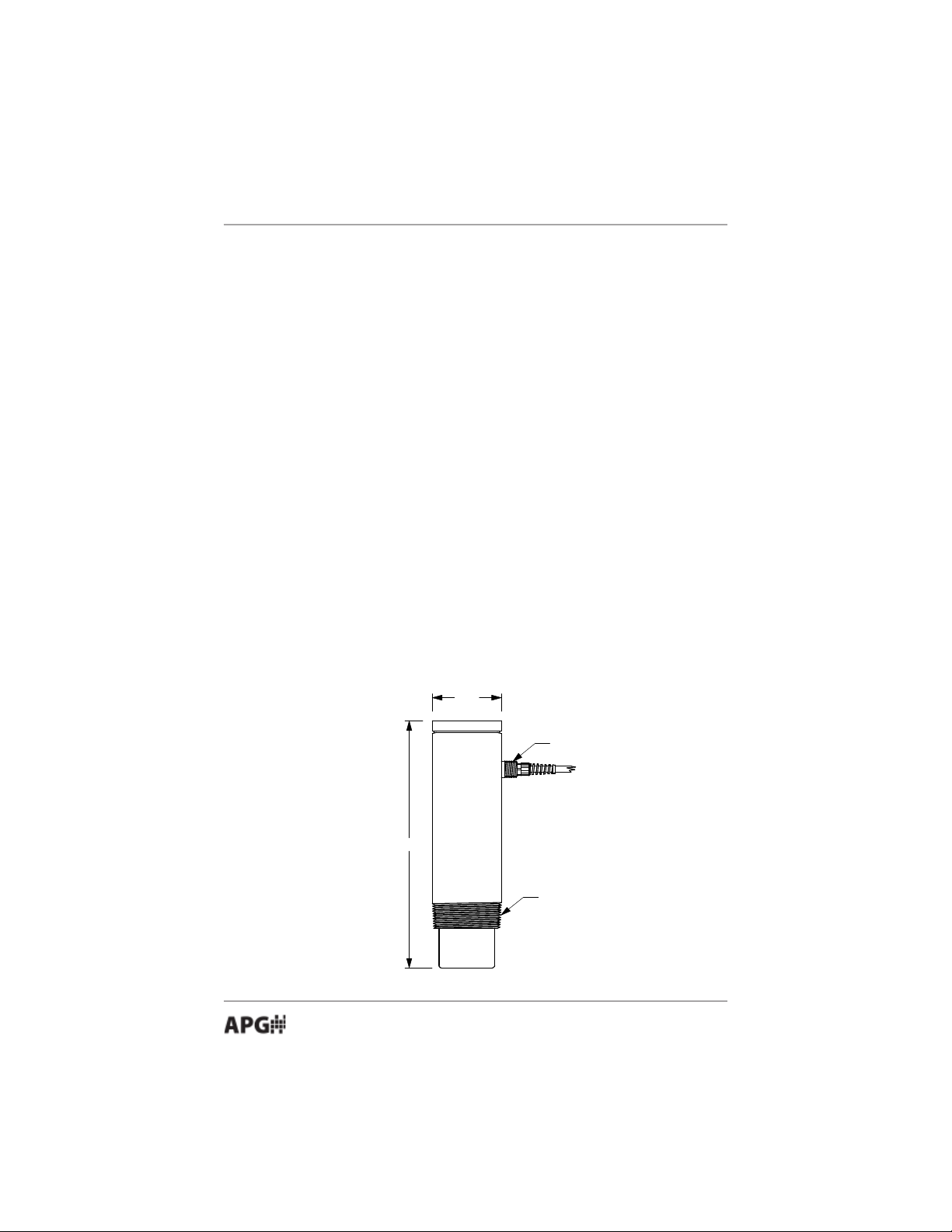
3.5"
12.5"
3" NPT
1/2" NPT
• Introducing
Thank you for purchasing the DCU-11 Programmable Ultrasonic Sensor.
These sensors combine a versatile range of features to handle even the toughest
measuring challenges in tank and environmental monitoring and control.
Sensor features include:
• Total Programmability
• Built-in display for easy setup and distance readings
• Rugged, PVC housing for harsh environments with polyurethane
encased electronics for moisture, shock, and vibration resistance
• Microprocessor-controlled with analog and relay outputs
• PVC enclosed ceramic transducer for use in wet or dry applications
• Distance range of 2 ft. to 50 ft.
4
Automation Products Group, Inc.
APG...Providing tailored solutions for measurement applications
Tel: 1/888/525-7300 • Fax: 1/435/753-7490 • www .apgsensors.com • sales@apgsensors.com
Rev. A2, 11/06 DCU-1104 and DCU-1108
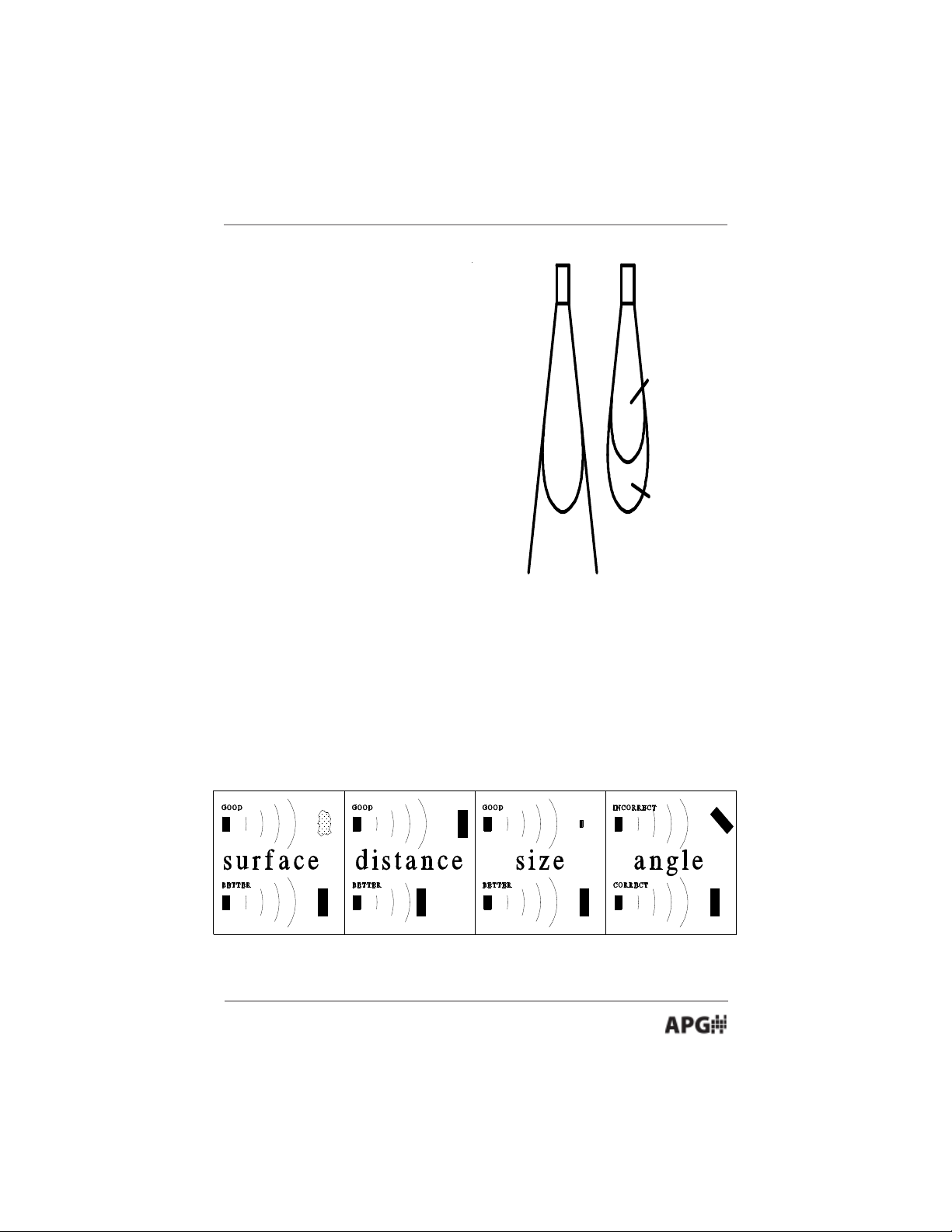
detection
area
beam spread
low sensitivity
and
pulses
high sensitivity
and
pulses
• Understanding Ultrasonics
Ultrasonic sensors measure distance
using a transducer to send out ultrasonic
bursts. Each burst contains a series of 120 pulsed sound waves that emit in the
shape of a cone, reflect off the target, and
are received by the sensor. The time
required for the sound burst to travel to
and from the target is converted into a
distance measurement by the sensor.
Ultrasonic sensing is affected by
several factors including the target
surface, distance, size, and angle. The
following considerations will help ensure
the best possible target conditions.
Surface
The ideal target surface is hard and smooth and perpendicular to the face of
the transducer. This surface will reflect a greater amount of signal than a soft,
sound wave absorbent surface. A target with poor sound wave reflection
characteristics will reduce the operating distance of the sensor and decrease its
accuracy.
Automation Products Group, Inc.
APG...Providing tailored solutions for measurement applications
Tel: 1/888/525-7300 • Fax: 1/435/753-7490 • www .apgsensors.com • sales@apgsensors.com
5

DCU-1104 and DCU-1108 Rev. A2, 11/06
Distance
The shorter the distance from the sensor to an object, the stronger the
returning echo will be. Therefore, as the distance increases, the object requires
better reflective characteristics to return a sufficient echo.
Size
A large object will have a greater surface area to reflect the signal than a
small one, therefore, a large target will be detected at a greater distance than a
small target. The surface area recognized as the target is generally the portion
closest to the sensor.
Angle
The inclination of the object's surface facing the ultrasonic sensor affects the
reflectivity of the object. The portion perpendicular to the sensor returns the
echo. If the entire surface is at a great enough angle, the signal will be reflected
away from the sensor and no echo will be detected. Generally a target at an
angle greater than 5 degrees off perpendicular will not be detected.
6
APG...Providing tailored solutions for measurement applications
Tel: 1/888/525-7300 • Fax: 1/435/753-7490 • www .apgsensors.com • sales@apgsensors.com
Automation Products Group, Inc.

Rev. A2, 11/06 DCU-1104 and DCU-1108
• Installation
1. Installation, use and maintenance shall be in
accordance with the manufacturer’s instructions, the
National Electrical Code and any applicable local codes.
2. Electrical equipment connected to associated
apparatus should not use or generate more than
250Vrms.
3. Tampering or replacement with nonfactory
components may adversely affect the safe use of the
system.
Automation Products Group, Inc.
APG...Providing tailored solutions for measurement applications
Tel: 1/888/525-7300 • Fax: 1/435/753-7490 • www .apgsensors.com • sales@apgsensors.com
7
DCU-1104 and DCU-1108 Rev. A2, 11/06
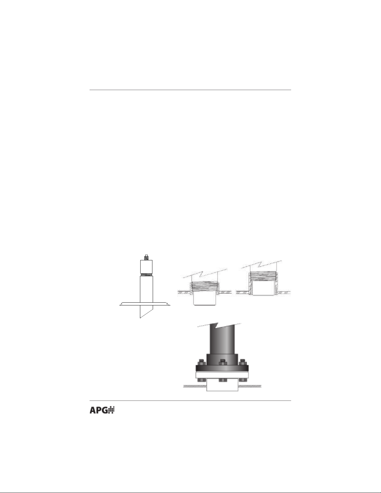
Top of Tank
Stand Pipe
10-45
o
CUT
• Installation
The DCU-11 sensor should be mounted so that it has a clear sound path to
the level monitored. Mount the sensor away from tank walls and inlets. The
path should be free from obstructions and as open as possible for the 18° beam
pattern (9° off axis). Follow the guidelines mentioned in "Understanding
Ultrasonics", earlier in this manual. When using a stand pipe to mount the
sensor above the tank, the stand pipe should be seamless and no longer than 4
in. to provide a smooth path for the sound waves to propagate into the tank.
Seams from couplers, nipples or gaskets can cause erroneous echoes and
degrade the sensors performance.
The DCU-11 can be mounted in a coupler, or flange by using the 3 in.
threaded case. It can also be mounted using a Uni-Strut mounting bracket.
The minimum detection range of the DCU-11 is 2 ft. The sensor should be
mounted to ensure the target does not come closer than the minimum
range or erroneous readings may result.
To mount the DCU-11 for Class 1 Division 2 Groups A, B, C, and D, see the
Hazardous Mounting section of this manual.
*Soft gasket
material is
recommended with
flange mounting.
8
APG...Providing tailored solutions for measurement applications
Tel: 1/888/525-7300 • Fax: 1/435/753-7490 • www .apgsensors.com • sales@apgsensors.com
Automation Products Group, Inc.
Rev. A2, 11/06 DCU-1104 and DCU-1108
• Wiring
RED ................... 10 - 30 VDC (24 VDC recommended)
BLACK .............. POWER SUPPLY GROUND
YELLOW........... ANALOG GROUND
ORANGE ........... 4-20 mA ANALOG OUTPUT
BLUE................. RELAY 1 COMMON
GRA Y ................ RELA Y 1 NORMALLY OPEN
PURPLE ............ RELAY 2 COMMON
BROWN ............. RELA Y 2 NORMALLY OPEN
GREEN .............. CLOCK SYNCHRONIZA TION
WHITE............... DIGITAL OUT
SHIELD ............. TERMINA TE AT POWER SOURCE *
• Cable is a 10 conductor with shield, 22 AWG, 6 ft. (1.83 m) length.
• Ground and Analog ground are connected internal to the DCU-11.
* Shield is not connected in the DCU-11 and should be grounded at the
power source.
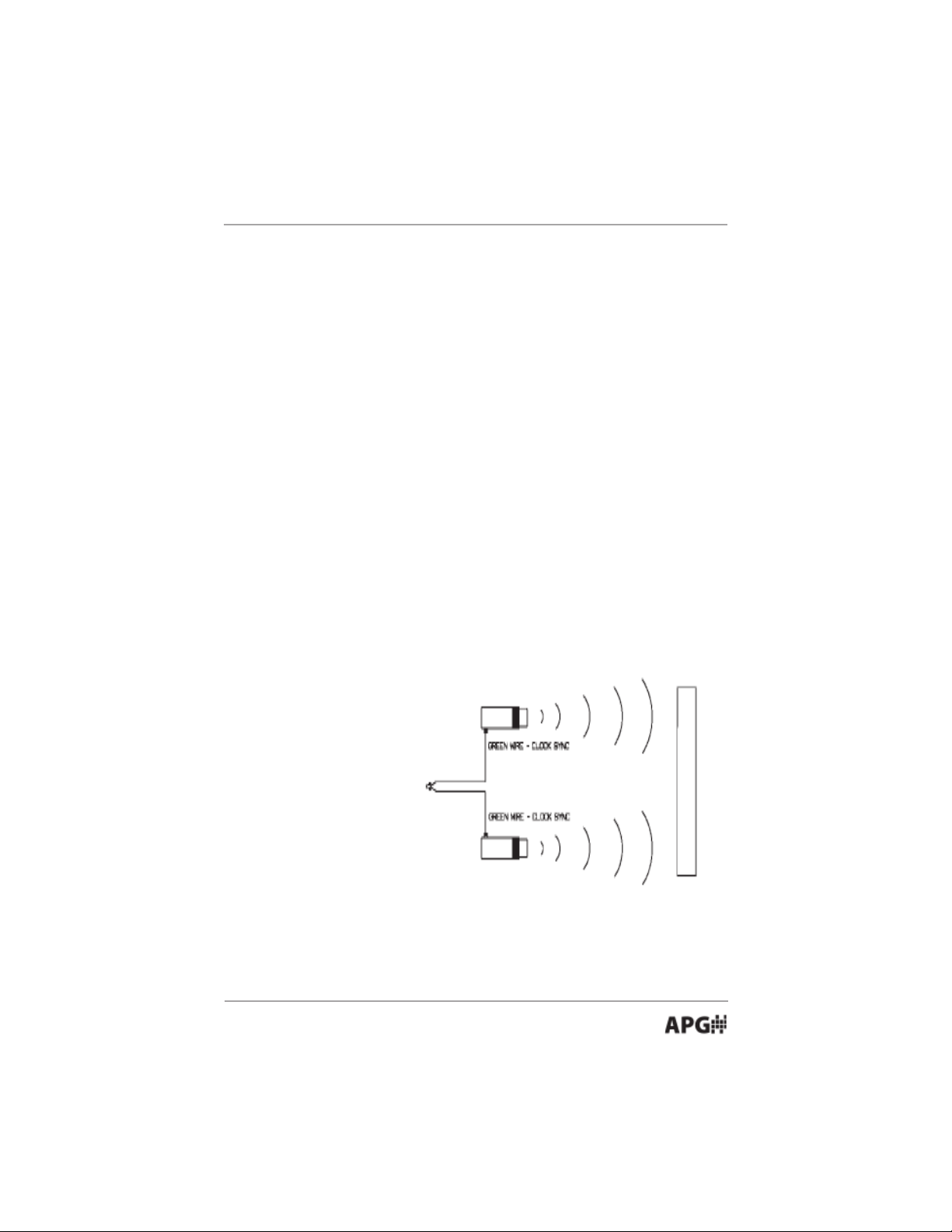
Wiring for Clock
Synchronization
The DCU-11 has the
capability to synchronize
the transmit pulses of
multiple sensors. When
sensors are mounted in
close proximity to one
another the sensors
should be synchronized to
help prevent cross talk
between sensors.
Wiring for a Digital
Out
The digital output is a pulse width signal which corresponds to the distance
being detected by the DCU-11 sensor. The digital signal is typically used in
conjunction with a APG (ACC-1007) or (ACC-1008) remote readout.
Automation Products Group, Inc.
APG...Providing tailored solutions for measurement applications
Tel: 1/888/525-7300 • Fax: 1/435/753-7490 • www .apgsensors.com • sales@apgsensors.com
9
DCU-1104 and DCU-1108 Rev. A2, 11/06
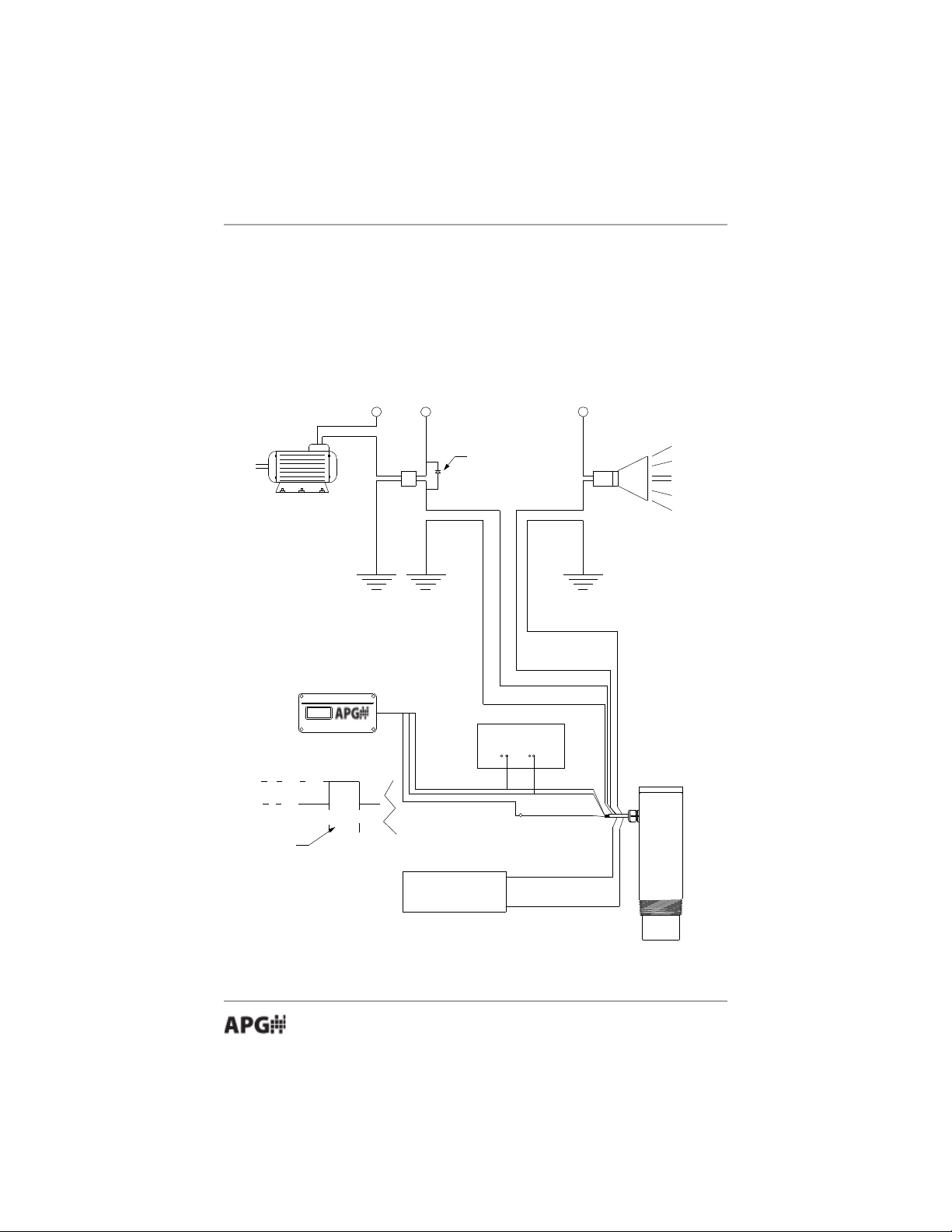
RELAY
24 V DC
COIL
A.C.
24VDC
24VDC
Alarm
Gray (N.O.)
Blue (Common)
Brown (N.O.)
Purple (Common)
Swamping Diode
Power Supply
24VDC Neg.
White
Red 10-30VDC
Black Neg.
White Digital out
I/O Device
0 Volts
5 Volts
signal to travel from
transducer to target
and return to
transducer. The width
varies and is proportional
to the target distance.
Orange 4-20mA (+)
Yellow 4-20mA (-)
ACC-1008
Length of time for
Wiring for a Relay Output
When switching a highly capacitive or inductive load, a swamping diode
should be used. This will protect the internal relay from possible damage and
prevent electrical noise from being introduced to the sensor which could result
in false readings.
DCU-11 Wiring Diagram
10
APG...Providing tailored solutions for measurement applications
Tel: 1/888/525-7300 • Fax: 1/435/753-7490 • www .apgsensors.com • sales@apgsensors.com
Automation Products Group, Inc.
 Loading...