

Page 1

PRODUCTS
AUT OMATION
Operator’s Manual
GROUP, INC.
AGV-1000
Rev. A3, 10/08
Doc. 9002669
Automation Products Group, Inc.
APG...Providing tailored solutions for measurement applications
Tel: 1/888/525-7300 • Fax: 1/435/753-7490 • www.apgsensors.com • E-mail: sales@apgsensors.com
Page 2

AGV-1000 Rev. A3, 10/08
Table of Contents
Warranty ......................................................................................... 3
Introducing...................................................................................... 4
Understanding Ultrasonics............................................................. 5
Mounting......................................................................................... 7
Wiring.............................................................................................. 8
Programming................................................................................ 10
Parameters ................................................................................... 11
Inputs ............................................................................................ 14
Outputs ......................................................................................... 16
Specifications ................................................................................ 17
Dimensions.................................................................................... 17
Automation Products Group, Inc.
2
APG...Providing tailored solutions for measurement applications
Tel: 1/888/525-7300 • Fax: 1/435/753-7490 • www .apgsensors.com • sales@apgsensors.com
Page 3

Rev. A3, 10/08 AGV-1000
• Warranty and W arranty Restrictions
APG warrants its products to be free from defects of material and workmanship
and will, without charge, replace or repair any equipment found defective upon
inspection at its factory, provided the equipment has been returned,
transportation prepaid, within 24 months from date of shipment from factory .
THE FOREGOING WARRANTY IS IN LIEU OF AND EXCLUDES ALL OTHER
WARRANTIES NOT EXPRESSL Y SET FOR TH HEREIN, WHETHER
EXPRESSED OR IMPLIED BY OPERATION OF LAW OR OTHER WISE
INCLUDING BUT NOT LIMITED T O ANY IMPLIED WARRANTIES OF
MERCHANT ABILITY OR FITNESS FOR A PAR TICULAR PURPOSE.
No representation or warranty, express or implied, made by any sales
representative, distributor, or other agent or representative of APG which is not
specifically set forth herein shall be binding upon APG. APG shall not be liable
for any incidental or consequential damages, losses or expenses directly or
indirectly arising from the sale, handling, improper application or use of the
goods or from any other cause relating thereto and APG’s liability hereunder, in
any case, is expressly limited to the repair or replacement (at APG’s option) of
goods.
Warranty is specifically at the factory. Any on site service will be provided at
the sole expense of the Purchaser at standard field service rates.
All associated equipment must be protected by properly rated electronic/
electrical protection devices. APG shall not be liable for any damage due to
improper engineering or installation by the purchaser or third parties. Proper
installation, operation and maintenance of the product becomes the
responsibility of the user upon receipt of the product.
Returns and allowances must be authorized by APG in advance. APG will
assign a Return Material Authorization (RMA) number which must appear on
all related papers and the outside of the shipping carton. All returns are subject
to the final review by APG. Returns are subject to restocking charges as
determined by APG’s “Credit Return Policy”.
Automation Products Group, Inc.
APG...Providing tailored solutions for measurement applications
Tel: 1/888/525-7300 • Fax: 1/435/753-7490 • www .apgsensors.com • sales@apgsensors.com
3
Page 4

AGV-1000 Rev. A3, 10/08
• Introducing
The AGV-1000 ultrasonic collision avoidance system is designed to provide
a flexible solution for automated vehicles and other collision avoidance
applications. The system can be configured with up to six transducers
(standard), with the option of up to eight transducers for a wide coverage area.
The AGV-1000 is designed with the following features:
• Short and long range modes, each with eight programmable “SLOW” and
“STOP” functions.
• The ability to temporarily disable specific transducers to prevent
unwanted object detection.
• Adjustable random pulsing to reduce transducer cross-talk and multiple
echo interference.
• Transducer error detection circuitry, with an “ERROR” output and
programmable “SLOW” or “STOP” on error functions.
• Programmable adjustments for transmit signal strength and return signal
amplification.
• Redundant “STOP” outputs for added safety.
• RS-232 interface.
• 10 to 30 VDC operating voltage.
Automation Products Group, Inc.
4
APG...Providing tailored solutions for measurement applications
Tel: 1/888/525-7300 • Fax: 1/435/753-7490 • www .apgsensors.com • sales@apgsensors.com
Page 5
Rev. A3, 10/08 AGV-1000
detection
area
beam spread
low sensitivity
and
pulses
high sensitivity
and
pulses
• Understanding Ultrasonics
Ultrasonic sensors measure distance
using a transducer to send out ultrasonic
bursts. Each burst contains a series of 1-20
pulsed sound waves that emit in the shape
of a cone, reflect off the target, and are
received by the sensor. The time required
for the sound burst to travel to and from
the target is converted into a distance
measurement by the sensor.
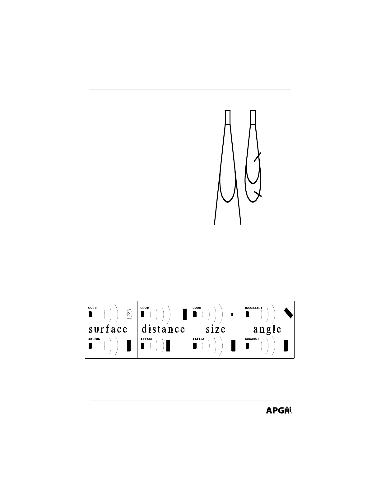
Ultrasonic sensing is affected by several
factors including the target surface,
distance, size, and angle. The following
considerations will help ensure the best
possible target conditions.
Surface
The ideal target surface is hard and smooth and perpendicular to the face of
the transducer. This surface will reflect a greater amount of signal than a soft,
sound wave absorbent surface. A target with poor sound wave reflection
characteristics will reduce the operating distance of the sensor and decrease its
accuracy.
Automation Products Group, Inc.
APG...Providing tailored solutions for measurement applications
Tel: 1/888/525-7300 • Fax: 1/435/753-7490 • www .apgsensors.com • sales@apgsensors.com
5
Page 6

AGV-1000 Rev. A3, 10/08
Distance
The shorter the distance from the sensor to an object, the stronger the
returning echo will be. Therefore, as the distance increases, the object requires
better reflective characteristics to return a sufficient echo.
Size
A large object will have a greater surface area to reflect the signal than a
small one, therefore, a large target will be detected at a greater distance than a
small target. The surface area recognized as the target is generally the portion
closest to the sensor.
Angle
The inclination of the object's surface facing the ultrasonic sensor affects the
reflectivity of the object. The portion perpendicular to the sensor returns the
echo. If the entire surface is at a great enough angle, the signal will be reflected
away from the sensor and no echo will be detected. Generally a target at an
angle greater than 5 degrees off perpendicular will not be detected.
Automation Products Group, Inc.
6
APG...Providing tailored solutions for measurement applications
Tel: 1/888/525-7300 • Fax: 1/435/753-7490 • www .apgsensors.com • sales@apgsensors.com
Page 7

Rev. A3, 10/08 AGV-1000
6.70"
8.00"
2.94"
7.00"
1.75"
6.00"
0.25"
1.825"
1.70"
3.375"
3.00"
0.1875"
• Mounting
The AGV-1000 utilizes thru-hole type mounting for the controller and the
transducer assemblies. See the drawings below for the mounting hole
dimensions and spacing.
NOTE: Drawings not shown to scale.
Controller Housing
Transducer Bracket
Automation Products Group, Inc.
APG...Providing tailored solutions for measurement applications
Tel: 1/888/525-7300 • Fax: 1/435/753-7490 • www .apgsensors.com • sales@apgsensors.com
7
Page 8

AGV-1000 Rev. A3, 10/08
OR
Solid State Relay
Output Circuitry
OUT1(+)
OUT1(-)
Output Circuitry
OUT1(+)
OUT1(-)
+V
+V
Solid State Relay
OPTION 1
To Main Processor Input
OUTPUT at +V = Normal Condition
OUTPUT at GND = SLOW/STOP/ERROR
OPTION 2
To Main Processor Input
OUTPUT at Ground = Normal Condition
OUTPUT at +V = SLOW/STOP/ERROR
I(max) = 100 mA
R= 600 at 12 Volts (20 mA)
R = 1.2K at 24 Volts (20 mA)
OUTPUT
Relay = CLOSED = NORMAL
Relay = OPEN = ACTIVE
AGV-1000 Circuitry
+V
OPTION 2
Switch + VDC
0 V = Off
+V = ON
I(typ) = 10mA
INPUT
Voltage across input terminals = ON
IN(+) = IN(-) = OFF
IN1(+)
IN1(-)
IN1(+)
IN1(-)
OR
Input Circuitry
Opto-Isolated Input
Input Circuitry
Opto-Isolated Input
OPTION 1
Sink current to GND
IN(-) = GND = ON
IN(-) = FLOAT = OFF
10mA (typ)
• Wiring
The AGV-1000 utilizes plug and socket terminal-block wiring connections.
The system is designed to operate on 10 to 30 VDC. The supply voltage
connects to terminals 1 & 2 or 11 & 12. The AGV-1000 has six “Front-End”
circuits, each controlling a transducer. The terminals labeled FE(+) on the
diagram below, refer to the “Front End” circuits. Connect the transducer (+)
wires to the corresponding FE terminals. The T(-) terminals refer to the
transducer negative connections. The GND terminals are for grounding the
transducer cable shield wires. The IN and OUT terminals refer to the inputs and
outputs of the system. The options for wiring the inputs and outputs are shown
in the diagram below. To help reduce induced noise, all unused INPUTS should
be jumpered between the (+) and the corresponding (-) terminals.
NOTE: The maximum transducer cable length is 6 ft.
8
(Continued on next page)
Automation Products Group, Inc.
APG...Providing tailored solutions for measurement applications
Tel: 1/888/525-7300 • Fax: 1/435/753-7490 • www .apgsensors.com • sales@apgsensors.com
Page 9

Rev. A3, 10/08 AGV-1000
Attach Transducer #1 RED to FE1(+)
Attach Transducer #1 BLACK to T1(-)
Attach Transducer #1 Shield to GND
Attach Transducer #2 RED to FE2(+)
Attach Transducer #2 BLACK to T2(-)
Attach Transducer #2 Shield to GND
Attach Transducer #3 RED to FE3(+)
Attach Transducer #3 BLACK to T3(-)
Attach Transducer #3 Shield to GND
Attach Transducer #4 RED to FE4(+)
Attach Transducer #4 BLACK to T4(-)
Attach Transducer #4 Shield to GND
Attach Transducer #5 RED to FE5(+)
Attach Transducer #5 BLACK to T5(-)
Attach Transducer #5 Shield to GND
Attach Transducer #6 RED to FE6(+)
Attach Transducer #6 BLACK to T6(-)
Attach Transducer #6 Shield to GND
Attach Transducer #7 RED to FE?(+)
Attach Transducer #7 BLACK to T7(-)
Attach Transducer #7 Shield to GND
Attach Transducer #8 RED to FE?(+)
Attach Transducer #8 BLACK to T8(-)
Attach Transducer #8 Shield to GND
11
12 13 14
1 2 3 4 5 6 7 8 9 10
15 16 17 18 19 20 21 22 23 24 25 2627 28
F
E
1
(
+
)
T
1
(
-
)
G
N
D
F
E
2
(
+
)
T
2
(
-
)
G
N
D
F
E
3
(
+
)
T
3
(
-
)
G
N
D
F
E
1
(
+
)
G
ND
F
E
2
(
+
)
T
7
(
-
)
F
E
3
(
+
)
G
ND
G
N
D
G
ND
G
N
D
F
E
4
(
+
)
T
4
(
-
)
F
E
5
(
+
)
T
5
(
-
)
F
E
6
(
+
)
T
6
(
-
)
F
E
4
(
+
)
F
E
5
(
+
)
F
E
6
(
+
)
T
8
(
-
)
1 2 3 4 5 6 7 8 9 10
11 12 13 14 15 16 17 18 19 20
V
(
+
)
G
ND
I
N
1
(
+
)
I
N
1
(
-
)
I
N
2
(
+
)
I
N
2
(
-
)
O
U
T
1
(
+
)
O
U
T
1
(
-
)
O
UT
2
(
+
)
O
U
T
2
(
-
)
V
(
+
)
G
N
D
I
N3
(
+
)
I
N
3
(
-
)
I
N4
(
+
)
I
N
4
(
-
)
O
U
T
3
(
+
)
O
UT
3
(
-
)
O
U
T
4
(
+
)
O
UT
4
(
-
)
• Wiring (continued)
Attach the discrete input controls to terminals 3-6 and 13-16. The solid state relay
outputs (terminals 7-10 and 17-20) are rated for a maximum current of 130 mA.
NOTE: The AGV-1000 can be optionally wired with 7 or 8 transducers as follows:
Transducer 7: RED to terminal 10 (share FE1); 11 (share FE2); or 14 (share FE3),
BLACK to terminal 12, and SHIELD to terminal 13.
BLACK to terminal 26, and SHIELD to terminal 27.
The limitation of using more than 6 transducers is that transducers 7 and/or 8 must each
Transducer 8: RED to terminal 24 (share FE4); 25 (share FE5); or 28 (share FE6),
share a FE (Front End) circuit with one of transducers 1-6. If a short circuit error occurs
on a shared FE, then the system will not be able to distinguish which transducer has the
error. As a result, the error will be reported on both transducers.
APG...Providing tailored solutions for measurement applications
Automation Products Group, Inc.
Tel: 1/888/525-7300 • Fax: 1/435/753-7490 • www .apgsensors.com • sales@apgsensors.com
9
Page 10

AGV-1000 Rev. A3, 10/08
• Programming
The AGV-1000 is designed to be programmed through an RS-232 interface to a PC
serial port. The “interfacing software” is used to send and receive a “setup file” which is
used to edit the parameters of the sensor. The “setup file” is in a simple text format, and is
easily edited using a text editing program like Microsoft “Notepad” or “W ord”.
Programming Steps:
1. Run the setup file in the floppy disk #1 that came with the AGV-1000.
Follow the instructions to install the AGV-1000 software.
2. Remove the AGV unit’s top cover to access the 9 pin connector. Connect
the powered AGV unit to the serial port of the PC. Run the software labeled
A1000 SWx (x = the software version number). Distance readings and
sensor status information should be displayed in the software windows
when communication is established.
3. Click on the button labeled “Receive File From AGV”. You will be
prompted to choose a file name and path to save the received file. This will
retrieve a “text” file from the AGV. This text file contains the system
parameter setting. Choose a file name (be sure to include the .txt extension;
For example: mysettings.txt) and save the file.
4. Using Microsoft’ s “Notepad”, “Word”,
or another text editing program, open
the file you saved from the AGV-1000.
Change all the settings and parameters
necessary for your application. Do NOT
re-arrange the order of parameters in the
text file, change only the parameter
value settings. Re-save the updated file.
5. Using the AGV-1000 software, send the
edited text file to the system. When the
window at the bottom of the software
reads “Data Received”, the new settings
have taken effect. Re-adjusting the sensor
parameters is as easy as editing the saved
text file, and sending it to the AGV-1000
The AGV-1000 Software
using the AGV-1000 software.
10
Automation Products Group, Inc.
APG...Providing tailored solutions for measurement applications
Tel: 1/888/525-7300 • Fax: 1/435/753-7490 • www .apgsensors.com • sales@apgsensors.com
Page 11

Rev. A3, 10/08 AGV-1000
• Parameters
VERSION NUMBER (0 to 65535)
Allows the user to assign a “version number” for tracking and referencing different setup
files.
FILE TYPE (User defined)
Allows the user to assign a “file- type” name for tracking and referencing different
setups.
TI GAIN (0-8)
Sets the maximum gain/amplification level that is applied to the return signals on all of the
Front-End circuits. The “Front-Ends” are the circuits that control the transducers. A TI
gain setting of 2 is recommended for most applications.
DIGITAL POT GAIN (40-200)
Sets the gain/amplification level for each of the six Front-End circuits within the limits of
the IT GAIN setting. NOTE: The TI gain together with the digital pot gain controls the
sensitivity of the AGV-1000.
BLANKING (0.229 meters Min.)
Sets the length of the dead zone in front of the transducers. Echo returns from inside the
blanking zone will be ignored. DO NOT set the blanking distance lower than the 0.229
meter minimum! Shorter blanking settings are used for testing purposes only.
PULSES (16-30)
Sets the number of pulse waves sent in each ultrasonic burst. This setting controls the
strength of the transmit signals.
SAMPLE RATE (80-250 msec)
Sets the delay between samples taken by the AGV-1000. A shorter delay will allow for
quicker detection of an obstacle
FAULTS (4-250)
Sets the number of transducer “short” or “open” circuit readings before the sensor
outputs an error condition. The faults are input to an “up-down” counter . For example,
suppose the faults parameter is set to 10. If 8 consecutive transducer “short circuit”
readings are taken, then the counter would increase to 8. If the sensor then receives 5
consecutive error free readings, then the counter would count down to 3. If the sensor
Automation Products Group, Inc.
APG...Providing tailored solutions for measurement applications
Tel: 1/888/525-7300 • Fax: 1/435/753-7490 • www .apgsensors.com • sales@apgsensors.com
11
Page 12

AGV-1000 Rev. A3, 10/08
then receives 7 more consecutive error readings the counter would reach 10 and an error
condition would then be output.
STOP ON ERROR (0=NO & 1=YES)
If this parameter is set to 1 (YES), the AGV-1000 will output a “stop” command
if the “F AULT” parameter error-limit is reached.
SLOW ON ERROR (0=NO & 1=YES)
If this parameter is set to 1 (YES), the AGV-1000 will output a “slow” command
if the “F AULT” parameter error-limit is reached.
GO-STOP (1-10)
Selects the number of consecutive times an object must be sampled in the
“STOP zone” (with the sensor in the “GO” condition) before the output will
change states from “GO” to “STOP”.
GO-SLOW (1-10)
Selects the number of consecutive times an object must be sampled in the
“SLOW zone” (with the sensor in the “GO” condition) before the output will
change states from “GO” to “SLOW”
SLOW-GO (1-10)
Selects the number of consecutive times that
NO objects are sampled in any
“zone” (with the sensor output in a “SLOW” condition) before the output will
change states from “SLOW” to “GO”
SLOW-STOP (1-10)
Selects the number of consecutive times an object must be sampled in the
“STOP zone” (with the sensor output in a “SLOW” condition) before the
output will change states from “SLOW” to “STOP”
STOP-GO (1-10)
Selects the number of consecutive times that
NO objects are sampled in any
“zone” (with the sensor output in a “STOP” condition) before the output will
change states from “STOP” to “GO”
STOP-SLOW (1-10)
Selects the number of consecutive times an object must be sampled in the
“SLOW zone” (with the sensor output in a “STOP” condition) before the
output will change states from “STOP” to “SLOW”
Automation Products Group, Inc.
12
APG...Providing tailored solutions for measurement applications
Tel: 1/888/525-7300 • Fax: 1/435/753-7490 • www .apgsensors.com • sales@apgsensors.com
Page 13

Rev. A3, 10/08 AGV-1000
Slow Zone
Stop Zone
Transducers
Vehicle
Go Zone
Detect
Add
RANDOM PULSE 1-6 (0 to 120 msec.)
The RANDOM PULSE parameters are used to set delays between samples from
each of the six front-end circuits. By assigning varied delays between samples,
the user can reduce transducer cross-talk and multiple-echo interferences. The
default settings have been used with good results and should not need
adjustment in most applications.
DETECT ADD (0 to 1 m)
The DETECT ADD feature “adds” a detection zone (of the specified length) in
front of the SLOW zone (see figure below). If an object enters the DETECT
ADD zone, then the sensor increases the sample rate and starts random pulsing.
This is designed to increase the response time of the sensor should the object
enter the SLOW zone.
APG...Providing tailored solutions for measurement applications
Tel: 1/888/525-7300 • Fax: 1/435/753-7490 • www .apgsensors.com • sales@apgsensors.com
Automation Products Group, Inc.
13
Page 14

AGV-1000 Rev. A3, 10/08
• Inputs
The AGV-1000 has four discrete inputs. Inputs 1 to 3 are used in combination
to select between different setups. Input 4 is used to select between LONG and
SHORT operating ranges. By changing the “on/off” combinations of inputs 1
to 3, we are able to get the 8 different input options below.
NOTE: Input 1 = least significant bit; Input 3 = most significant bit
INPUT 3 INPUT 2 INPUT 1 BINARY
Off Off Off 000
Off Off On 001
Off On Off 010
Off On On 011
On Off Off 100
On Off On 101
On On Off 110
On On On 111
On = Potential across IN(+) and IN(-)
Off = No potential across IN(+) and IN(-)
For each of the 8 input combinations, the user can set the following
parameters:
FRONT END ENABLE — (front-end circuit numbers 0 to 123456)
The Front End Enable parameters allow the user to define which of the six
front-end circuits are active for each of the 8 combinations of inputs 1-3. Each
front-end circuit controls a corresponding transducer. Assigning active frontend circuits is as simple as entering the numbers associated with the front-end
circuits that the user wishes to keep active. There are no limitations to which
front-ends are assigned to each input combination. You may activate all, some,
or none of the front-ends for each input combination.
Example: Suppose the user wants to fire only front-ends 1, 3 and 5 when input 3
is “on” and inputs 2 and 1 are “off”. The user would enter the numbers 135 in the
100 Front End Enable parameter. The order the front-end numbers are entered is
not important. Entering 513 will produce the same result as entering 135 or 531.
Automation Products Group, Inc.
14
APG...Providing tailored solutions for measurement applications
Tel: 1/888/525-7300 • Fax: 1/435/753-7490 • www .apgsensors.com • sales@apgsensors.com
Page 15

Rev. A3, 10/08 AGV-1000
SLOW & STOP zones — (0 to 4.064 m)
For each of the 8 combinations of inputs 1-3, the AGV-1000 also allows the
user to program the length (in Meters) of the SLOW and STOP zones (see figure
on previous page) If an obstacle is detected inside the SLOW or STOP zone,
then the AGV-1000 will output a SLOW or STOP condition.
LONG & SHORT modes — (Of f = SHORT mode and On = LONG mode)
Input 4 is designed to allow the user to switch between LONG range and
SHORT range settings for each of the eight STOP and SLOW zone setting. This
gives the user 8-SLOW and 8-STOP settings in both the LONG and SHORT
modes, for a total of 16 independent SLOW and STOP settings.
Automation Products Group, Inc.
APG...Providing tailored solutions for measurement applications
Tel: 1/888/525-7300 • Fax: 1/435/753-7490 • www .apgsensors.com • sales@apgsensors.com
15
Page 16

AGV-1000 Rev. A3, 10/08
• Outputs
The AGV-1000 has four solid state relay outputs, rated at 130 mA maximum.
WARNING! DO NOT EXCEED THIS RATING. If 130 mA is insuf ficient, the
AGV -1000’s relays can be used to control external relays rated to handle your
current needs. The four outputs are “Normally Open” relays that operate in
the “closed” position. An error, a target, or power loss will cause the
appropriate output(s) to open.
Output 1 = SLOW
Output 2 = STOP
Output 3 = ERROR
Output 4 = STOP
The redundant “STOP” outputs (2 & 4) are for added safety. STOP output
may be wired to a dual-input safety relay.
If the error-detection circuits detect a short or open condition on any of the
transducers, then output 3 will open. The user has the option to assign a
“STOP” or “SLOW” output when an “ERROR” is detected.
16
Automation Products Group, Inc.
APG...Providing tailored solutions for measurement applications
Tel: 1/888/525-7300 • Fax: 1/435/753-7490 • www .apgsensors.com • sales@apgsensors.com
Page 17

Rev. A3, 10/08 AGV-1000
6.70"
8.00"
2.94"
7.00"
1.75"
6.00"
0.25"
1.825"
1.70"
3.375"
3.00"
0.1875"
• Specifications
Detection Range .............. 0.229 m to 4.064 m (9 inches to 12.4 feet)
Input Voltage .................... 10-30 VDC
Inputs............................... RS-232 and (4) discrete
Outputs............................ (4) solid state relays (130 mA max) and RS-232.
Accuracy ......................... 0.25% of range
Adjustments .................... RS-232
T otal Current Draw: .......... TBA
Transducer Type: ............. Electrostatic
Operating T emperature:.... -30 to 70°C
Sample Rate:..................... Programmable 4 to 12 Hz
Beam Pattern: ................... 8° off axis
• Dimensions
Controller ......................... 6.7 in. H x 6 in. W x 2.95 in. D
Transducer Assembly ...... 3 in. H x 1.825 in. W x 1.7 in. D
(Both housings are aluminum)
Automation Products Group, Inc.
APG...Providing tailored solutions for measurement applications
Tel: 1/888/525-7300 • Fax: 1/435/753-7490 • www .apgsensors.com • sales@apgsensors.com
17
Page 18

AGV-1000 Rev. A3, 10/08
Notes
18
Automation Products Group, Inc.
APG...Providing tailored solutions for measurement applications
Tel: 1/888/525-7300 • Fax: 1/435/753-7490 • www .apgsensors.com • sales@apgsensors.com
Page 19

Rev. A3, 10/08 AGV-1000
Notes
Automation Products Group, Inc.
APG...Providing tailored solutions for measurement applications
Tel: 1/888/525-7300 • Fax: 1/435/753-7490 • www .apgsensors.com • sales@apgsensors.com
19
Page 20

AUT OMATION
APG...Providing tailored solutions
for measurement applications
Automation Products Group, Inc.
T el: 1/888/525-7300
Fax: 1/435/753-7490
e-mail: sales@apgsensors.com
www.apgsensors.com
GROUP, INC.
1/435/753-7300
PRODUCTS
Automation Products Group, Inc.
1025 W. 1700 N.
Logan, UT 84321
 Loading...