

Page 1

AUTOMATION
Operator’s Manual
PRODUCTS
GROUP, INC.
ACF-10 Series
Acoustical Flow Sensor for Solids
Rev. 1a, 2/03
Automation Products Group, Inc.
APG...Providing tailored solutions for measurement applications
Tel: 1/888/525-7300 • Fax: 1/435/753-7490 • www.apgsensors.com • E-mail: sales@apgsensors.com
Page 2

Rev. 1a, 2/03 ACF-10 Series
Table of Contents
Warranty ......................................................................................... 2
Introduction .................................................................................... 3
Specifications .................................................................................. 4
Principle of Operation .................................................................... 5
Installation ...................................................................................... 6
Wiring ............................................................................................. 7
Adjustment ...................................................................................... 8
Cautions on Handling ................................................................... 11
Check Up ...................................................................................... 12
Dimensions ................................................................................... 13
Automation Products Group, Inc.
APG...Providing tailored solutions for measurement applications
Tel: 1/888/525-7300 • Fax: 1/435/753-7490 • www.apgsensors.com • sales@apgsensors.com
1
Page 3

ACF-10 Series Rev. 1a, 2/03
• Warranty and Warranty Restrictions
APG warrants its products to be free from defects of material and
workmanship and will, without charge, replace or repair any equipment found
defective upon inspection at its factory, provided the equipment has been
returned, transportation prepaid, within 18 months from date of shipment from
factory.
THE FOREGOING WARRANTY IS IN LIEU OF AND EXCLUDES ALL
OTHER WARRANTIES NOT EXPRESSLY SET FORTH HEREIN, WHETHER
EXPRESSED OR IMPLIED BY OPERATION OF LAW OR OTHERWISE
INCLUDING BUT NOT LIMITED TO ANY IMPLIED WARRANTIES OF
MERCHANTABILITY OR FITNESS FOR A PARTICULAR PURPOSE.
No representation or warranty, express or implied, made by any sales
representative, distributor, or other agent or representative of APG which is
not specifically set forth herein shall be binding upon APG. APG shall not be
liable for any incidental or consequential damages, losses or expenses directly
or indirectly arising from the sale, handling, improper application or use of the
goods or from any other cause relating thereto and APG’s liability hereunder,
in any case, is expressly limited to the repair or replacement (at APG’s option)
of goods.
Warranty is specifically at the factory. Any on site service will be provided at
the sole expense of the Purchaser at standard field service rates.
All associated equipment must be protected by properly rated electronic/
electrical protection devices. APG shall not be liable for any damage due to
improper engineering or installation by the purchaser or third parties. Proper
installation, operation and maintenance of the product becomes the
responsibility of the user upon receipt of the product.
Returns and allowances must be authorized by APG in advance. APG will
assign a Return Material Authorization (RMA) number which must appear on
all related papers and the outside of the shipping carton. All returns are
subject to the final review by APG. Returns are subject to restocking charges
as determined by APG’s “Credit Return Policy”.
Automation Products Group, Inc.
APG...Providing tailored solutions for measurement applications
2
Tel: 1/888/525-7300 • Fax: 1/435/753-7490 • www.apgsensors.com • sales@apgsensors.com
Page 4

Rev. 1a, 2/03 ACF-10 Series
• Introduction
The ACF-10 Acoustical Flow Sensor is a compact unit that detects audible
noise made by powders and grains which is converted to a relay output.
In addition, since the ACF-10 is attached to the outside of the pipe or chute
and does not contact directly with the grains to be detected, the ACF-10 will
not have critical problems of flow fluctuations caused by conventional contacttype sensor inside the pipes and chutes, and with abrasion and corrosion
problems of the contact-type sensor. The ACF-10 can be easily attached to
existing pipes with straps.
The ACF-10 is easily adjusted with the use of four LED.
Automation Products Group, Inc.
APG...Providing tailored solutions for measurement applications
Tel: 1/888/525-7300 • Fax: 1/435/753-7490 • www.apgsensors.com • sales@apgsensors.com
3
Page 5

ACF-10 Series Rev. 1a, 2/03
• Specifications
Operating Characteristics
On Indication ................... Red LED (4)
Output Capacity:
Relay Contact ............... 240 V 2 A AC
30 V 2 A DC (resistive load)
Sensitivity Adjustment..... Adjusting by offset and gain trimmers
Output Functions ............. Detect switch
On Delay adjusting trimmer (approx. 0.1 to 7 sec.)
Off Delay adjusting trimmer (approx. 0.1 to 7 sec.)
Ambient Temperature ...... -10 to 70°C (14 to 158°F) without dewing
Ambient Humidity ........... Max. 85% RH
Electrical Characteristics
Power Supply Voltage ..... 22~264 VDC AC (50/60 Hz)
Withstand Voltage ............ 1,500 VAC 1 minute (between line terminals and
output terminals)
Insulation Resistance ....... 500 VDC 100 MΩ (between line terminals and
output terminals)
Power Consumption ........ Approx. 2.5 VA (at 100 VAC)
Mechanical Characteristics
Vibration Proof ................ 60~2000 Hz 10 G
Others
Material ............................ ABS, PC
Construction ..................... Drip-proof (IP54)
Installation ....................... Attaching band or metal fixtures (option)
Wire Inlet ......................... PF1/2 (cable gland method, gasket I.D. ø10 and ø8)
Automation Products Group, Inc.
APG...Providing tailored solutions for measurement applications
4
Tel: 1/888/525-7300 • Fax: 1/435/753-7490 • www.apgsensors.com • sales@apgsensors.com
Page 6

Rev. 1a, 2/03 ACF-10 Series
• Principle of Operation
When grains flow within a distributed tube such as a pipe or a chute, by
collision and friction between grains themselves or between grains and the wall
of the distributed tube, various sounds and vibrations will be generated.
The sound pickup of the ACF-10 attached outside the distributed tube
receives the generated sounds and vibrations and converts the signal to a relay
output.
Explanation of Functions
Offset Adjustment
By adjusting the signals (noise: sounds and vibrations generating during the
operation of the surrounding equipment) from the sound pickup when the
grains are not flowing, the component of noise can be cancelled.
Gain Adjustment
When the grains flows, by adjusting to amplify only the component of
signals, the signals can be increased to a desired voltage.
Automation Products Group, Inc.
APG...Providing tailored solutions for measurement applications
Tel: 1/888/525-7300 • Fax: 1/435/753-7490 • www.apgsensors.com • sales@apgsensors.com
5
Page 7

ACF-10 Series Rev. 1a, 2/03
• Installation
The ACF-10 can be attached by fastening the band or the metal fixtures with
two bolts.
Cautions in Selecting a Place to be Attached
Select a place where a lot of sounds and vibrations are generating to install
the ACF-10. Be sure to install the receiving part so that it can contact firmly
with the wall of a distributed tube. If the receiving part does not contact firmly
due the rugged surface of the wall, paint the surface with silicon grease etc. to
increase the contact efficiency. Unless the receiving part is in contact firmly
with the wall, the sensor will be insensitive.
Automation Products Group, Inc.
APG...Providing tailored solutions for measurement applications
6
Tel: 1/888/525-7300 • Fax: 1/435/753-7490 • www.apgsensors.com • sales@apgsensors.com
Page 8

Rev. 1a, 2/03 ACF-10 Series
• Wiring
1
23NO4
Line
Supply Voltage: 24-264V AC/DC
Relay Contact Output: 240V 2A AC
(resistive load)
Automation Products Group, Inc.
APG...Providing tailored solutions for measurement applications
Tel: 1/888/525-7300 • Fax: 1/435/753-7490 • www.apgsensors.com • sales@apgsensors.com
7
Page 9

ACF-10 Series Rev. 1a, 2/03
• Adjustment
1
NON
DETECT
ZERO RY ON
6
DETECT
OFFON
DELAYDELAYGAINOFFSET
5432
1. DETECT Switch For shifting the magnetizing state of the
output relay. The magnetizing state of the
output relay is as follows:
At Non-Detection At Detection
Detect On OFF ON
Non Detect ON OFF
2. OFFSET Adjusting Trimmer An offset adjusting trimmer for noise
component
left ... larger right ... smaller
3. GAIN Adjustment Trimmer An adjusting trimmer for amplifying only
input signals
left ... smaller right ... larger
4. ON DELAY Adjusting Trimmer A time adjusting trimmer for ON DELAY
Max. setting time is approx. 7 seconds
5. OFF DELAY Adjusting Trimmer A time adjusting trimmer for OFF
DELAY. Max. setting time is approx. 7
seconds
6. LED Display The red LED (4 pieces) indicate the
intensity of input signals. When the LED
illuminate, the relay will be switched on.
Automation Products Group, Inc.
APG...Providing tailored solutions for measurement applications
8
Tel: 1/888/525-7300 • Fax: 1/435/753-7490 • www.apgsensors.com • sales@apgsensors.com
Page 10

Rev. 1a, 2/03 ACF-10 Series
Preparations
Attach the ACF-10 to a distributed tube to check up again the wiring before switching
on. After switching on, the ACF-10 starts operating in an initial time of some 2 seconds
by the initial time circuit. Within the initial delay time, the relay will not operate.
(1) Flow Detection
Set the OFFSET trimmer to center, the GAIN trimmer to extreme left (min.)
and the DETECT switch to DETECT position before starting the following
procedures.
Operation Indication
1 ★ Stop the flow grains ZERO RY ON
(The magnitude of noise ❍ ❍ ❍ ❍
component is indicated)
2 Rotate the OFFSET trimmer to ZERO RY ON
illuminate the ZERO LED ❍ ❍ ❍ ❍
3 ★ Start flowing grains. ZERO RY ON
Rotate the GAIN trimmer to ad- ❍ ❍ ❍ ❍
just to illuminate RY ON LED
❊
❊
❊
(2) Plugged Detection
Set the OFFSET trimmer to center, the GAIN trimmer to extreme left (min.)
and the DETECT switch to DETECT position before starting the following
procedures.
Operation Indication
1 ★ Grains flowing. ZERO RY ON
(Rotate the GAIN trimmer 3-4 ❍ ❍ ❍ ❍
readings to the right)
2 Rotate the OFFSET trimmer to ZERO RY ON
a position where the RY ON ❍ ❍ ❍ ❍
LED is put out.
3 Rotate the GAIN trimmer to ad- ZERO RY ON
just to illuminate RY ON LED ❍ ❍ ❍ ❍
4 ★ Stop the flow of grains. ZERO RY ON
❍ ❍ ❍ ❍
❊
Automation Products Group, Inc.
APG...Providing tailored solutions for measurement applications
Tel: 1/888/525-7300 • Fax: 1/435/753-7490 • www.apgsensors.com • sales@apgsensors.com
❊
❊
❊
9
Page 11

ACF-10 Series Rev. 1a, 2/03
Other Functions
(1) Setting of DETECT switch
• Depending upon position of DETECT switch, the relay will operate as
follows:
Relay Contact
Detect Side OFF OPEN
Non Detect Side ON CLOSE
Relay Contact
Detect Side ON CLOSE
Non Detect Side OFF OPEN
(2) Setting of DELAY TIME
ON DELAY OFF DELAY
0.1 to 7 seconds 0.1 to 7 seconds
ON DELAY: Delay in output for change from non-detection to detection.
OFF DELAY: Delay in output for change from detection to non-detection.
Automation Products Group, Inc.
APG...Providing tailored solutions for measurement applications
10
Tel: 1/888/525-7300 • Fax: 1/435/753-7490 • www.apgsensors.com • sales@apgsensors.com
Page 12
Rev. 1a, 2/03 ACF-10 Series
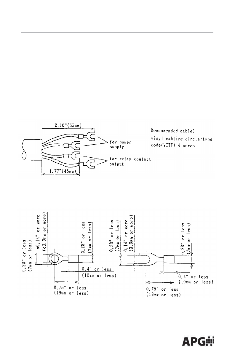
• Cautions on Handling
Wiring
Use the connection cables of ø5 to ø10 mm cross section.
If using cables other than specified diameter and strained cables, drip-proof
must be maintained.
Treat the cable as shown in the following figure.
After passing the cable through the cable gland, making press-fit is
recommended for easy-to-work.
Shape of solderless terminals for cable
Use the solderless terminal with the size as shown in the figure below.
Recommended press-fit terminal: nominal 1.25-3.5
Use the terminal with insulating tube.
Automation Products Group, Inc.
APG...Providing tailored solutions for measurement applications
Tel: 1/888/525-7300 • Fax: 1/435/753-7490 • www.apgsensors.com • sales@apgsensors.com
11
Page 13

ACF-10 Series Rev. 1a, 2/03
Other Cautions
• If the ACF-10 is dropped or receive a strong shock, it may be damaged.
Handle with care.
• Do not use the ACF-10 in a vapor and corrosive gases or misty
environments.
• Be sure to check up the terminal numbers before wiring. Be sure to fasten
the cable gland and the cover. If the fastening is loose, this may damage the
drip-proof.
• When using the ACF-10 outside, install to avoid direct sunlight or attach a
sunshading cover to avoid the temperature rise and the effect of ultraviolet
rays.
• Check Up
Check up the ACF-10’s operational functions with the following procedures.
Be sure to wire the ACF-10 before switching on. In approximately 2 seconds,
set the OFFSET trimmer in the center to tap lightly the receiving part by a
finger nail. When the illumination of the LED moves rightward from the zero
point, the operations are regarded as normal.
Automation Products Group, Inc.
APG...Providing tailored solutions for measurement applications
12
Tel: 1/888/525-7300 • Fax: 1/435/753-7490 • www.apgsensors.com • sales@apgsensors.com
Page 14
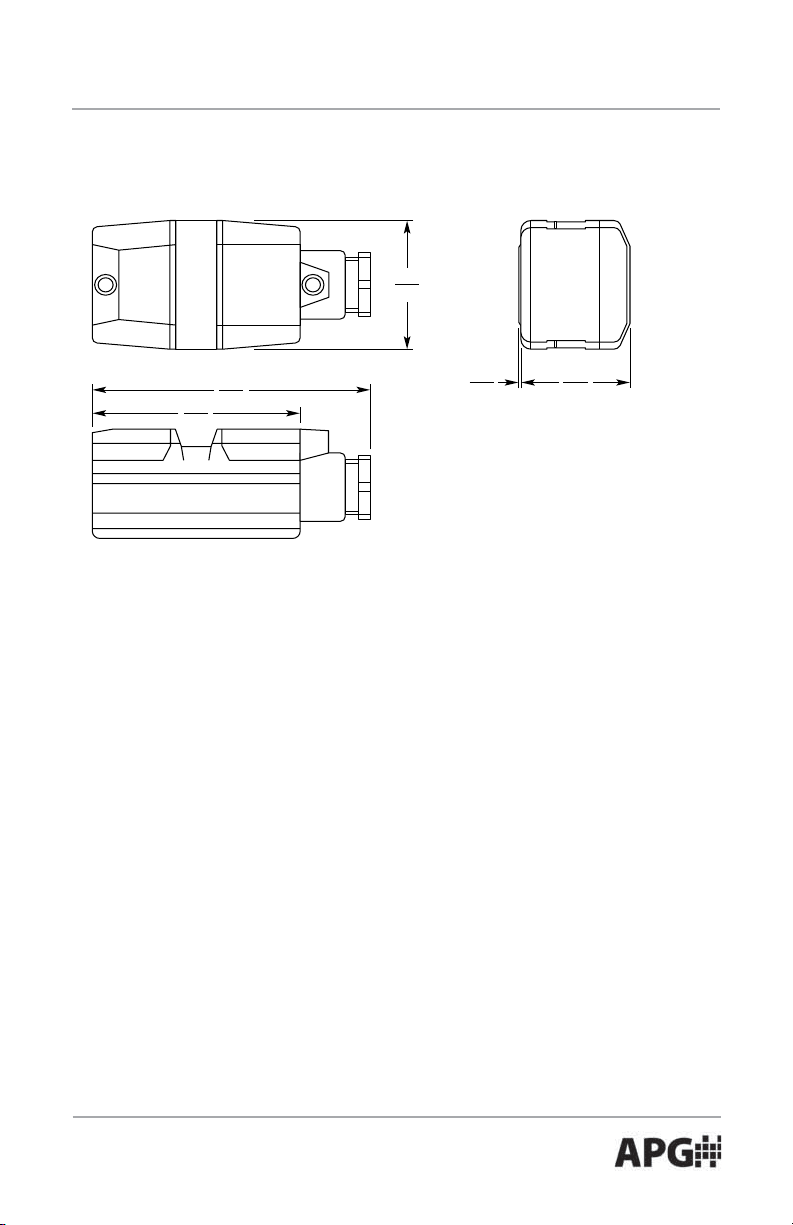
Rev. 1a, 2/03 ACF-10 Series
• Dimensions — in./mm
1.97
50
3.15
80
4.21
107
0.02
0.5
1.65
42
Automation Products Group, Inc.
APG...Providing tailored solutions for measurement applications
Tel: 1/888/525-7300 • Fax: 1/435/753-7490 • www.apgsensors.com • sales@apgsensors.com
13
Page 15

AUTOMATION
APG...Providing tailored solutions
for measurement applications
Automation Products Group, Inc.
Tel: 1/888/525-7300
Fax: 1/435/753-7490
GROUP, INC.
1/435/753-7300
PRODUCTS
e-mail: sales@apgsensors.com
www.apgsensors.com
Automation Products Group, Inc.
1025 W. 1700 N.
Logan, UT 84321
 Loading...