

Page 1
INSTRUCTION MANUAL
Rear Projection - GB43HD09, GBHD5109
Please read this manual carefully before operation.
Page 2
BEFORE OPERATION
Dear Customer:
Congratulations! You have purchased one of the
finest Color TVs on the market!
This manual will help you use the many exciting
and useful features to make your TV viewing more
enjoyable than ever before.
Before operating your TV set, please read all these
safety and operating instructions completely and
then retain for future reference.
Safety Precautions
WARNING:
TO REDUCE THE RISK OF FIRE OR ELECTRIC
SHOCK, DO NOT EXPOSE THIS APPLIANCE TO
RAIN OR MOISTURE.
RISK OF ELECTRIC SHOCK
DO NOT OPEN
CAUTION : TO REDUCE THE RISK OF ELEC-
TRIC SHOCK, DO NOT REMOVE COVER(OR
BACK). NO USER SERVICEABLE PARTS IN-
SIDE. REFER SERVICING TO QUALIFIED
SERVICE PERSONNEL.
The symbol is intended to alert the user
to the presence of "dangerous voltage"
within the product's enclosure that may
be strong enough to cause an electric
shock.
DO NOT TRY TO SERVICE THIS
PRODUCT YOURSELF.
Customer's Record
You will find the model number and chassis num-
ber on the back of your TV set.
Record these numbers in the spaces provided
below.
Refer to them whenever you call upon your Apex
dealer regarding this product.
Model Number: GB4308, GB5108
Chassis Number:
Avoid displaying stationary images on your TV
screen for extended periods of time. Stationary
patterns generated by computer displays, video
games, stock market reports, etc. can become
permanently engrained on the picture tube. This
damage is not protected by your warranty as it is
the result of misuse. Should you wish to use your
Apex Television to display still images, it is always
advisable to reduce brightness and contrast set-
tings. Never leave a video game or computer dis-
play unattended.
NOTE TO CABLE INSTALLER IN THE USA:
This reminder is provided to call your attention to
Article 820 - 40 of the NEC that provides guide-
lines for proper grounding and, in particular,
specifies that the cable ground shall be connect-
ed to the grounding system of the building, as
close to the point of cable entry as practical.
This symbol is intended to alert the user
to the presence of important operating
and maintenance instructions in the
manual.
CAUTIONS:
TO PREVENT ELECTRIC SHOCK, DO NOT USE
THIS POLARIZED PLUG WITH AN EXTENSION
CORD RECEPTACLE OR OTHER OUTLET UN-
LESS THE PRONGS CAN BE FULLY INSERTED
INTO THE OUTLET TO PREVENT ANY EXPOSURE
OF THE PRONGS ON THE POLARIZED PLUG.
Page 3
BEFORE OPERATION (continued)
Important Safety Instructions
CAUTION
PLEASE READ THESE iNSTRUCTIONS, KEEP THESE iNSTRUCTiONS AND HEED ALL WARNINGS. FOLLOW ALL INSTRUCTIONS.
Electrical energy can perform many useful functions. This TV set has been engineered and manufactured to assure your personal safety. However
improper use can result in potential electrical shock or fire hazards. In order not to defeat the safe guards incorporated in this TV set, observe the follow-
ing basic rules for antenna/TV installation, use and servicing. All operating and use instructions should be followed.
Do not remove the cabinet cover. This may expose you to dangerous voltages. Refer all servicing to qualified service personnel.
Power Sources - The TV set should beoperated onlyfrom thetype of power source indicated on the TV set or as indicated in the Operation Manual.
Ifyou are not sureof the typeof power supply in your home,consult your local power company.For "iV sets designed to operate from battery power,or
other sources, referto the operating instructions.
Grounding or Polarization - Do not defeat the safety purpose of the polarized or grounding-type plug. A polarized plug has two blades with one wider
than the other. A grounding - type plug has two blades and a third grounding prong. The wide blade or the third prong is provided for your
safety. If the provided plug does not fit into your outlet, consult an electrician for replacement of the obsolete outlet.
AlternateWarnings - This plug will only fit intoa grounding-type power outlet. This isa safety feature.
Ifyou are unableto insert the plug intothe outlet,contact your electricianto have asuitableoutlet installed.Do not defeat the safety purposeof the ground-
ing plug.
Power-Cord Protection - Protect the power cord from beingwalked on or pinched, particularly at plugs, convenience receptacles,and the pointwhere
they exit from the TV.
Overloading - Do not overload wall outlets, extension cords or integral convenience receptacles as this can result in fire or electric shock.
Lightning - For added protectionfor thisTV set during a lightningstorm, or when it is left unattended and unused for longperiods of time, unplugit from
the wall outlet and disconnectthe antenna or cable system. Thiswill preventdamage to the productdue to lightning and power-linesurges.
If a snapping or popping sound from a TV set is heard continuously or frequently while the TV set is operated, unplug the "iV set and consult your dealer
or service technician. It is normal for some TV sets to make occasional snapping or popping sounds, per_cularly when being turned on or off.
Heat - Do not install near any heat sources such as radiators, heat registers, stoves, or other apparatus (including amplifiers) that produce heat.
Accessories - Do not place the "iV set on an unstable cart, stand, tdpod, bracket, or table. The TV set may fall, causing serious injury to a child or adult,
and serious damage to the TV set. Use only with a cart, stand, tripod, bracket, or table recommended by the manufacturer, or accessory recommended
by the manufacturer, or sold with the TV set, and should use a mounting accessory recommended by the manufacturer.
A product and cart combination should bemoved with care. Quick stops,excessive force, anduneven surfaces may cause theTV set andcart combi-
nation to overturn.
Water and Moisture Warnings - Do not use the TV set near water-for example, near a bath tub, wash bowl, kitchen sink, or laundry tub; in a wet base-
ment; or near a swimming pool; and the like. The TV set should not be exposed to dripping or splashing and no objects filled with liquids, such as vases,
should be placed on the "iV set.
Object and Liquid Entry - Never pushobjects of any kind into the TV set through openings as they may touch dangerous voltage points orshort-out
parts that could result in a fire or electric shock.Never spill liquid of any kind on the "iV set.
Cleaning - Unplug the TV set from the wall outlet before cleaning or polishing it. Do not use liquid cleaners or aerosol cleaners. Use a dry cloth for
cleaning the exterior of the TV set.
Attachments - Do not use attachments not recommended by the product manufacturer as they may cause hazards or electric shock.
Ventilation - Slots and openings in the cabinet are provided for ventilationand to ensure reliableoperation of the "iV set and to protect it from overheat-
ing, and these openings must not be blocked or covered. The openings should never be blockedby placing the TV set on a bed, sofa, rug,or other simi-
lar surface. This"iV set should not be placed in a built-in installation such as a bookcaseor rack unless properventilation is provided or the manufactur-
er's instructions have been adhered to.
Page 4
BEFORE OPERATION (continued)
Precautions (continued)
Damage Requiring Service - Unplug the TV set from the wall outlet and refer servicing to qualified service personnel
under the following conditions:
a. If the power cord or plug is damaged or frayed.
b. If liquid has been spilled or objects have fallen into the TV set.
c. If the TM set has been exposed to rain or water.
d. If the TV set has been subject to excessive shock by being dropped, or the cabinet has been damaged.
e. If the TV set does not operate normally by following the operating instructions. Adjust only those
controls that are covered by the operating instructions as an improper adjustment of other controls may result in dam-
age and will often require extensive work by a qualified technician to restore the TV set to its normal operation.
f. When the TV set exhibits a distinct change in performance-this indicates a need for service.
Servicing - Do not attempt to service the TV set yourself as opening or removing covers may expose you to dangerous
voltage or other hazards. Refer all servicing to qualified service personnel.
Replacement Parts - When replacement parts are required, be sure the service technician has used replacement parts
specified by the manufacturer or have the same characteristics as the original parts. Unauthorized substitutions may
result in fire, electric shock, or other hazards.
Safety Check - Upon completion of any service or repairs to the TV set, ask the service technician to perform routine safety
checks to determine that the TV set is in proper operating condition.
Disposal - When the TV set reaches the end of its useful life, improper disposal could result in a picture tube implosion.
Ask a qualified service technician to dispose of the TV set.
ANTENNA
Outdoor Antenna Grounding- If an outdoor antenna is
installed, follow the precautions below.
An outdoor antenna system should not be located in the
vicinity of overhead power lines or other electric light or
power circuits, or where it can come in contact with such
power lines or circuits.
WHEN INSTALLING AN OUTDOOR ANTENNA SYSTEM,
EXTREME CARE SHOULD BE TAKEN TO KEEP FROM
CONTACTING SUCH POWER LINES OR CIRCUITS AS
CONTACT WITH THEM IS ALMOST iNVARIABLY FATAL
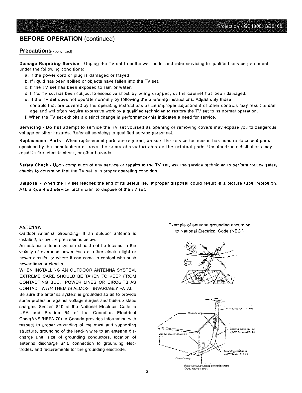
Be sure the antenna system is grounded so as to provide
some protection against voltage surges and built-up static
charges. Section 810 of the National Electrical Code in
USA and Section 54 of the Canadian Electrical
Code(ANSI/NFPA 70) in Canada provides information with
respect to proper grounding of the mast and supporting
structure, grounding of the lead-in wire to an antenna dis-
charge unit, size of grounding conductors, location of
antenna discharge unit, connection to grounding elec-
trodes, and requirements for the grounding electrode.
Example of antenna grounding according
to National Electrical Code (NEC)
Page 5
BEFORE OPERATION (continued)
FCC Warning
Class B Computing Device
Information to User
This equipment has been tested and found to comply with the limits for a class B digital device pursuant to
part 15 of FCC Rules. These limits are designed to provide reasonable protection against harmful interfer-
ence in a residential installation. This equipment generates, uses, and can radiate radio frequency energy
and, if not installed and used in accordance with the instructions, may cause harmful interference to radio
communications. However, there is no guarantee that interference will not occur in a particular installation.
If this equipment does cause harmful interference to radio or TV reception, which can be determined by
turning the equipment off and on, the user is encouraged to try to correct the interference by one or more of
the following measures:
1) Reorient or relocate the receiving antenna.
2) Increase the separation between the equipment and receiver
3) Connect the equipment into an outlet on a circuit different from that to which the receiver is con-
nected.
4) Consult the dealer or an experienced radio/TV technician for help and for additional suggestions.
The user may find the following booklet prepared by the Federal Communications Commission helpful:"How
to Identify and Resolve Radio -TV Interference Problems". This booklet is available from the US Government
Printing Office. Washington, D. C 20402, Stock No. 004-000-00345-4.
FCC Warning
The user is cautioned that changes or modifications not expressly approved by the manufacturer could void
the user's authority to operate the equipment.
NOTE: In order for an installation of the product to maintain compliance with the limits for a Class B device,
shielded cables must be used.
Page 6
Contents
Introducing the APEX Projection TV
Presenting the APEX Projection TV. ..................................................................................................... 9
Using this Manual ................................................................................................................................ 10
Installing and Connecting the Projection TV
Inserting Batteries into the Remote Control ......................................................................................... 11
Carrying the Projection TV. .................................................................................................................. 11
Installing the Projection TV. ................................................................................................................. 12
Connector Types ................................................................................................................................... 13
Projection TV Front panel .................................................................................................................... 14
Projection TV Rear panel .................................................................................................................... 14
Connecting the Antenna ....................................................................................................................... 15
Connecting an AV receiver. .................................................................................................................. 16
Connecting a VCD, VCR or camcorder. ............................................................................................. 17
Connecting a DVD Player with Component Video Connectors .......................................................... 18
Connecting a DVD Player with A/V Connectors ................................................................................. 18
Connecting a Digital TV Receiver. ...................................................................................................... 19
Using the Features
Using the Remote Control .................................................................................................................... 20
Powering on/off. ................................................................................................................................... 21
Watching the TV.................................................................................................................................... 22
Watching the Digital TV. ....................................................................................................................... 25
Using Browsing Channel Function ....................................................................................................... 25
Watching PIE ........................................................................................................................................ 26
Using the Menus
Overview ............................................................................................................................................... 27
Using the Video Menu .......................................................................................................................... 28
Using the Audio Menu .......................................................................................................................... 29
Using the System Menu ........................................................................................................................ 30
Using the Tune Menu ........................................................................................................................... 34
Other Information
Programming the Remote Control ........................................................................................................ 36
Operating Other Components with Your Projection TV Remote Control ............................................ 40
Troubleshooting .................................................................................................................................... 41
Specifications and Accessories ............................................................................................................. 42
Limited United States Warranty............................................................................................................ 43
* The OSD and figures shown in this manual may be somewhat different from the actual situation.
Page 7
INTRODUCTION This manual is for models GB43HD09 and GB51HD09.
Model GB5 IHD09 is used for illustration purposes.
Features
Some of features that you will enjoy with your new projection TV include:
• HDTV Monitor: Enables you to receive the 1080i, 720p, 480p, and 480i
digital TV formats. By using the YP_PRI/YPr_PR2 1Njacks, you can connect
a DTV (digital television) receiver to view DTV programs.
• 3D Y/C Comb Filter
• Film mode: Using the 3:2 Pulldown technology, the Film Mode feature
allows you to obtain a smooth picture movement when playing back movie
or other video sources on film.
• Browsing Channel : Allows you to view and choose channels from all
receivable channels scrolling on the screen without leaving the current
channel.
• Dual Tuner PIP: Allows you to watch two moving programs
at the same time.
• Auto Volume Control (AVC) : Equalizes volume levels so there is con-
sistent output between programs and commercials.
• BTSC Sound System: Enjoy stereo, bilingual and mono programs.
• BBE Sound Enhancement : This function can characterize the sound,
generate the playback sound ahnost like natural sound.
• DBE Sound Enhancement : You can make bass richer by boosting low
frequency.
• Component Video Inputs : Offers the best video quality for DVD (480p,
480i ) and digital set-top box (1080i, 720p, 480p, 480i) connections.
• S-VIDEO Inputs: Provides a high - quality image for connected equipment.
Page 8
INTRODUCTION (continued)
• On/off Timer: Turn on/off your projection TV or turn on a certain
channel number at the specified time.
• HELP Function
• Graphic OSD
• Protective Shield
• 1st Surface Mirror
• English/France/Spanish Menu
• User Convergence Adjustment:Allows you to adjust convergence.
• V-Chip Function: V - Chip technology allows parents to block
unsuitable programming for younger viewers.
• CCD function:Allows you to select from three closed caption modes
(for programs that are broadcast with closed captioning).
Using this manual
We recommend that you carefully review the contents of the
following three section in the order shown to ensure that you
fully understand the operation of your new projection TV.
1 Installing and Connecting the Projection TV
This section guides you through your initial setup. It shows
you how to install your projection TV, to connect your new
components and to connect the antenna and cable.
2 Using the Feature
This section shows you how to begin using your new projec-
tion TV. It also shows you how to use your remote control.
3 Using the menus
This sectiou teaches you how to access ou-screen menus aud
adjust your projection TV settings.
Page 9
INTRODUCTION (continued)
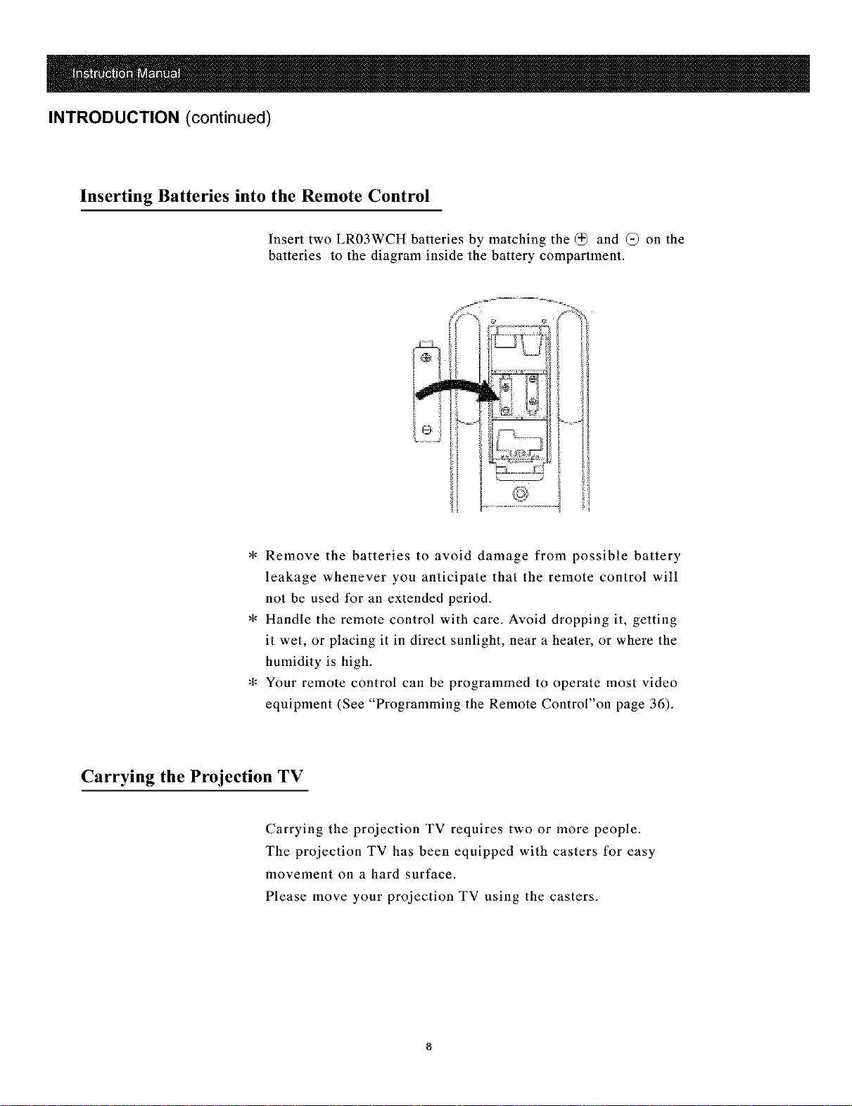
Inserting Batteries into the Remote Control
Insert two LR03WCH batteries by matching the @ and (_ on the
batteries to the diagram inside the battery compartment.
m
L J
* Remove the batteries to avoid damage from possible battery
leakage whenever you anticipate that the remote control will
not be used for an extended period.
* Handle the remote control with care. Avoid dropping it, getting
it wet, or placing it in direct sunlight, near a heater, or where the
humidity is high.
* Your remote control can be programmed to operate most video
equipment (See "Programming the Remote Control"on page 36).
Carrying the Projection TV
Carrying the projection TV requires two or more people.
The projection TV has been equipped with casters for easy
movement on a hard surface.
Please move your projection TV using the casters.
Page 10
INSTALLATION (continued)
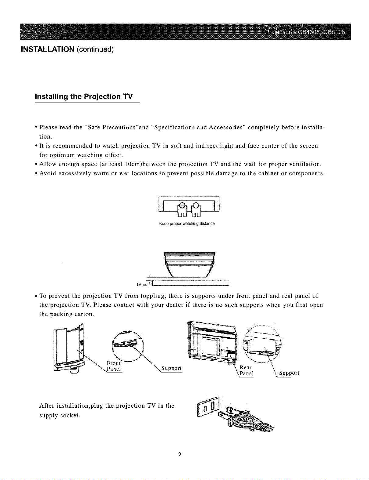
Installing the Projection TV
• Please read the "Safe Precautions'and "Specifications and Accessories" completely before installa-
tion.
• It is recommended to watch projection TV in soft and indirect light and face center of the screen
for optimum watching effect.
• Allow enough space (at least 10cm)between the projection TV and the wall for proper ventilation.
• Avoid excessively warm or wet locations to prevent possible damage to the cabinet or components.
Keep proper watching distance
• To prevent the projection TV from toppling, there is supports under front panel and real panel of
the projection TV. Please contact with your dealer if there is no such supports when you first open
the packing carton.
After installation,plug the projection TV in the
supply socket.
Page 11
INSTALLATION (continued)
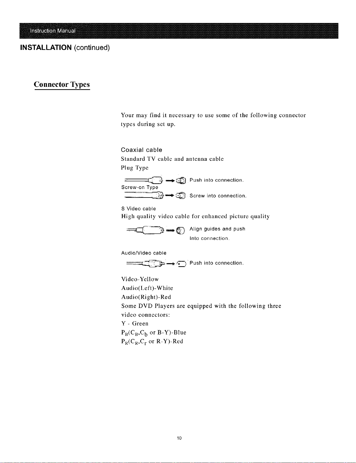
Connector Types
Your may find it necessary to use some of the following connector
types during set up.
Coaxial cable
Standard TV cable and antenna cable
Plug Type
--::_-j_ _;_,'-_, Push into connection,
Screw-on Type
_'"_"_ Screw into connection.
S Video cable
High quality video cable for enhanced picture quality
__Q Align guides and push
into connection.
Audio/Video cable
__--__ .._ Push into connection,
Video-Yellow
Audio(Left)-White
Audio(Right)-Red
Some DVD Players are equipped with the following three
video connectors:
Y - Green
PR(CR,C b or B-Y)-Blue
P_(C_,C r or R-Y)-Red
10
Page 12
INSTALLATION (continued)
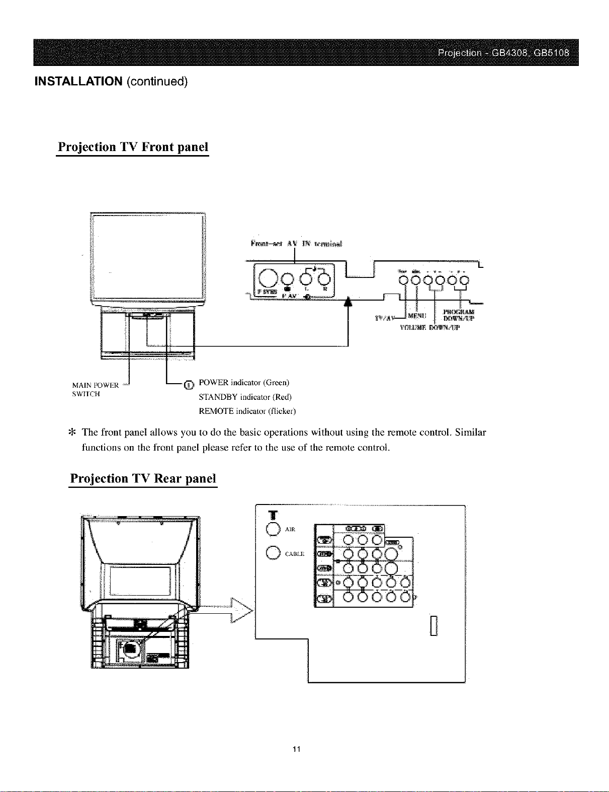
Projection TV Front panel
., L
_.22' /
MAIN POWIR "_ POWER indicator (Green)
SWITCH STANDBY indicator (Red)
REMOTE indicator (flicker)
The front panel allows you to do the basic operations without using the remote control. Similar
functions on the front panel please refer to the use of the remote control.
Projection TV Rear panel
AIR
l
11
Page 13
INSTALLATION (continued)
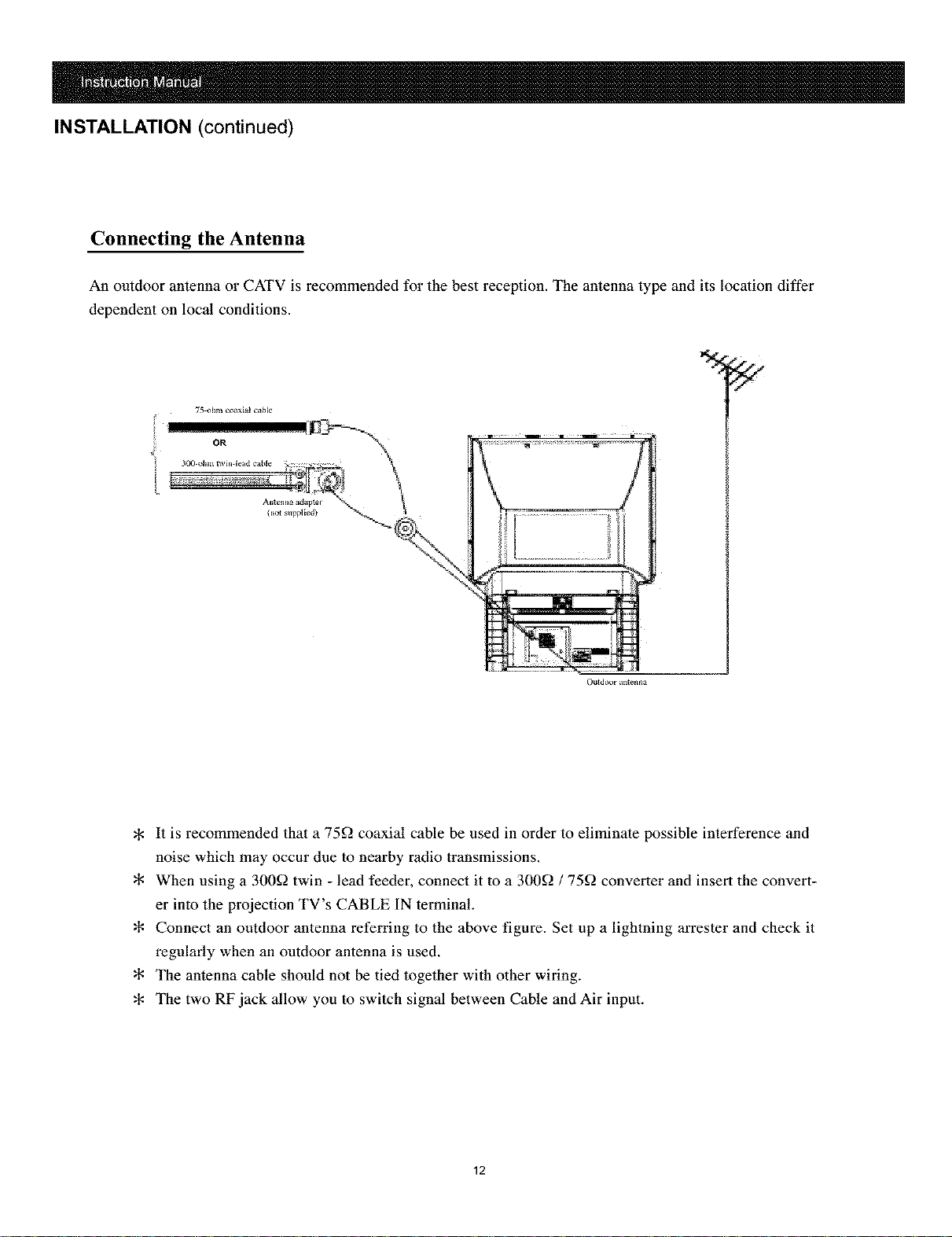
Connecting the Antenna
An outdoor antenna or CATV is recommended for the best reception. The antelma type and its location differ
dependent on local conditions.
%
Ou_d_'x_r an_e_a
It is recommended that a 75f2 coaxial cable be used in order to eliminate possible interference and
noise which may occur due to nearby radio transmissions.
When using a 300f] twin - lead feeder, connect it to a 300f2 / 75f] converter and insert the convert-
er into the projection TV's CABLE 1N terminal.
Connect an outdoor antenna referring to the above figure. Set up a lightning arrester and check it
regularly when an outdoor antenna is used.
The antenna cable should not be tied together with other wiring.
The two RFjack allow you to switch signal between Cable and Air input.
12
Page 14

INSTALLATION (continued)
Connecting an AV Receiver
Please turn off the power supply of the projection TV and external equipment before connection. Read the oper-
ation manuals of the external audio/video equipment that will be connected to the projection TV completely.
You can connect a stereo system to the MONITOR OUT terminals on the projection TV to enjoy a high quality
sound, or connect a VCR to the projection TV to record programs. The MONITOR OUT terminals output the
audio and video signals being monitored on the projection TV(main picture.)
>I<No output is available at MONITOR OUT when the signal is from YPBPRI or YPBPR2 of the main picture.
13
Page 15

INSTALLATION (continued)
Connecting a VCD, VCR or Camcorder
Disconnect all power before making any connections.
You can connect video equipment such as VCD, VCR or camcorder to the projection TV and enjoy the high-
quality picture.
If your video equipment has an S-VIDEO OUT terminal, connect it to the SVHS 1N terminal of the projection
TV. If not, connect it to the VIDEO 1N terminal.
Front panel
IT
:Signal direction
:Yellow terminal Video_
:White _erminal 'Audio L)
:Red terminal Audio R_
If you have a mono camcorder, connect
l--
its left audio output to the projection
TV's AUD10 L (INPUT) jack of AV1,
AV2 or FAV.
14
Page 16

INSTALLATION (continued)
Connecting a VCD Player with Component Video Connectors
Your DVD player has component (Y,B-Y, and R-Y)jacks.
Disconnect all power before making any connections.
1 Using three separate component video cables, connect the DVD player's Y, B-Y and R-Y jacks to
the YPBPkl or YPBP_2 jacks on the projection TV.
2 Using an audio cable, connect the DVD player's Audio OUT jacks to the projection TV's
YPBPR1 or YPBP_2 AUDIO 1N jacks.
3 Switch to YPbPrl or YPbPr2 mode, press the VIDEO button.
DVD_
999
Connecting a VCD Player with A/V Connectors
You DVD player does not have component (Y, PB,and Pu) jacks.
Disconnect all power before making any connections.
If you video equipment has an S-VIDEO OUT terminal, connect it to the SVHS IN terminal of the
projection TV. If not, connect it to the VIDEO 1N terminal.
@
i
15
Page 17

INSTALLATION (continued)
Connecting a Digital TV Receiver
Disconnect all power before making any connections.
1 Using three separate component video cables, connect the digital TV set-top box's Y, PB and PR
jacks to the YPBPR1 or YPBPR2 jacks on the projection TV.
2 Using an audio cable,connect the Digital TV Set-top box's Audio OUT jacks to the projection TV's
YPBPR1 or YPBPR2 AUDIO 1N jacks.
3 Press VIDEO to switch to YPbPrl or YPbPr2 mode.
8_-_rr_r pr_je_t_on'IV
¢
This projection TV is not compatible with digital TV receivers configured with RGB or VGA
output connectors.
If you digital TV set-top box has both VIDEO OUT and S-VIDEO terminals, you can also
connect them to the corresponding 1N terminal of the projection TV.
16
Page 18

Usingthe Features
Using the Remot control
Remote Control
Instructions in this manual are written for the remote control.Similar controls are also found on
the projection TV console.
The button design and specifications of the remote control are subject to change without notice.
Many TV features can be accessed directly through the remote control.Press "TV"(function but-
ton )on the remote control first to enter TV mode before operating the remote control.
17
Page 19

FEATURES (continued)
Power On / Off
Main power switch button
Plug supply press
in the socket and
and the indicator becomes green.
Power switch button on remote control
®
Power switch button on remote control
Main power switch button
The indicator flickers when receiving the signal emitted by the remote control (It does't flicker in
user convergence adjustment mode).
Auto off without signal reception
When a channel has no signal (e.g. the TV station fails to send signals ) and blue background
appears, the projection TV will automatically enter the STANDBY mode if no button is pressed
within 15 min. If Off Time is preset and the time left is less than 15 rain., the projection TV will
carry out first the Off Time.
:# The function of auto -off without signal doesn't work in the AV mode.
Press l_) on the remote control, the projection TV is turned off and enters STANDBY
mode .The indicator becomes red.
In the STANDBY mode, press _ or CH+/- on the remote control or P+/- on the front
panel to turn on the projection TV. The indicator becomes green.
To turn off the projection TV completely, press
on the projection TV to turn on the projection TV,
18
Page 20

FEATURES (continued)
Watching the TV
[] TV (FUNCTION)
Activates the remote control for use with the projection TV.
[] ANT (Antenna)
Press ANT first to display the current antenna mode. Press repeatedly
to change between the Cable and Air input.
[] POWER
Turns on or off the projection TV.
[] 100+ and 0~9
Use for direct channel selection.
To enter a three - digit channel number when "Anetnna" is set to "Cable",
press 100+ to call up "1--", then press 0~9 to enter the last two numbers.
* It is invalid if you enter channel number more than 69 (or less than 2)
in the Air mode or more than 125 (or less than 1) in the Cable mode.
* The channel number is red when entering by direct channel selection
buttons and the channel is set to "Skip ON".
* The projection TV will return to the TV mode if you press Channel
Number in the AV mode.
[] CH+/-
Press to scan through the channels (+ up or -down).
[] VOL +/-
Press to adjust the volume (+ up or - down).
[] RECALL
Press to alternate or jump back and forth between two channels or
sources. The projection TV will jump between the current channel and
the last channel selected.
[] MUTE
During watching projection TV program, press MUTE to eliminate sound.
Press it again to resume sound.
* Pressing VOL + call also cancel the MUTE function.
* Pressing VOL - call decrease the volume in the MUTE mode ,but not
cancel the MUTE mode.
19
Page 21

FEATURES (continued)
[] STILL
Press STILL repeatedly and the picture switches between the still and moving
modes.
* STILL is not available in YPbPrl or YPbPr2.
[] DISPLAY
Press to display the current program status, such as the channel number, sound
sysstem, antenna system and current time (if set ). To turn the display off, press
it again.
[] P-MODE
Press repeatedly to scroll through the following available video inputs:
Movie _ Normal _,- Vivid_Personal "-7
1
_--==
Movie: Select to display a finely detailed picture for low light enviromnent
Normal: Select to display a standard picture for normal viewing environment
Vivid: Select for enhanced picture contrast and sharpness.
Personal:User-set picture mode.
[] S-MODE
Press repeatedly to directly choose one of four different sound modes
thai best suits the program you are watching.
News_ Hall _Music _Personal "'1
!
,i
[] BBE
Press to turn on or off the BBE effect mode.
[] VIDEO
Press repeatedly to select projection TV signal sources shown as the
follows:
News: News/dialogue
Hall: Hall audio effect
Music: Concert hall audio effect
Personal: User-set sound mode
CHANNEL NO._ (AV 1)_ SVHS 1_ (AV2)
YPbPr2 "r_ YPbPrl _ F SVHS "_- (F AV) "r_ SVHS2
2O
Page 22

FEATURES (continued)
CHANNEL NO.
AV1
AV2
FAV
SVHS1
SVHS2
F SVHS
YPbPrl
YPbPr2
Radio Signal
AV 1 Signal
AV2 Signal
Front AV
S-VIDEO Signal 1N 1
S-VIDEO Signal 1N 2
Front S-VIDEO Signal 1N
DVD Component Signal and DTV Signal IN 1
DVD Component Signal and DTV Signal IN 2
* SVHS prevails when inserting AV-Video and SVHS simultaneously
(For detail, see page 31).
* If inserting SVHS and turning "S ldent" to ON, the corresponding
AV 1, AV2 or F AV will not be displayed (For detail, see page 30).
* To watch component signal and DTV signal, switch to YPbPrl or
YPbPr2 channel.
[] TIMER
You may use this function to watch the
desired program at the preset time and
turn on/off your projection TV at the
preset time.
Call up the item to be adjusted by pressing
CH+/- and adjust it by VOL+/-.
* The other items in TIMER SET menu
can only available after you finish Clock setting.
* "On Set", "Order Set" and "Off Set" can set to OFF/ONCE/
ALWAYS respectively. Your setting is one-time after your projection
TV is set to ONCE, and last forever after set to ALWAYS unless you
turn off the main power supply.
* "On Timer" and "On Channel" are not available when "On Set" is
set to OFF.
"Order Timer" and "Order Channel" are not available when "Order
Set" is set to OFF.
"Off Timer" is not available when "Off Set" is set to OFF.
* The timer setting will be cancelled automatically after turning off
the main power supply of the projection TV.
[] HELP
Press HELP to display the remote control profile. Press it again to exit.
Press CH+/- to highlight a button, and its function is displayed.
21
Page 23

FEATURES (continued)
Watching the Digital TV
When you have connected the DTV receiver, you can enjoy digital TV
programs. This projection TV is capable of receiving the 1080i,720p,480p
and 480i digital TV formats.
* This projection TV is not capable of display a native 720p format signal.
When a 720p format signal is received, it make down-conversion.
To view a digital TV program
1 Connect the DTV receiver to YPBPRI or YPBPR2 on the projection TV
(for detail, see page 19).
2 Press VIDEO to select YPbPrl or YPbPr2.
3 Select a digital channel on the DTV receiver. For detail, see the Opera-
tion Manual of the DTV receiver.
4 Adjust the volume of the projection TV as necessary.
* It is normal that OSD in 1080i is different from that in other modes.
Using Browsing Channel Function
Allows you to display multiple channels and select one directly.
1 Press on the remote control to browse channel and press it again to
exit.
The first nine receivable channels will appear one after another.
2 When the channel becomes moving picture and channel number is yellow,
press VOL+/-, the selected channel will enlarge for normal viewing.
3 At the receiving interval of the first nine channel and second nine channel,
press CH+/- to select the channel that you wish to wiew. The selected channel
becomes moving picture and channel number is yellow, press VOL+/-, the
selected chmmet will enlarge for normal viewing.
* Browsing Channel will not function when ' Pare ]tal Lock" is set ot ON or i]
AV mode.
22
Page 24

FEATURES (continued)
Watching PIP [] PIP ON/OFF
Press to turn on or off PIP function.
[] LOCATION
Press to change the position of the sub-picture. The position of the sub-pic-
ture wilt change in the order of lower right, lower left, upper left and upper
right corner of the screen.
[] SIZE
Press to adjust the size of the sub-picture. The sub-picture will change
between SMALL SIZE and BIG SIZE cyclically by pressing it repeatedly.
[] SWAP
Press to switch between the main and sub-picture.
[] PIP VIDEO
Press to realize switching between AV and TV.
* YPbPrl and YPbPr2 are not available in PIE
[] PIP CH+
Press to select a upper channel number for PIE
* You can only select the programs that are auto-searched and stored by
pressing PIP CH+.
[] PIP CH-
Press to select a lower channel number for PIE
* You can only select the programs that are auto-searched and stored by
pressing PIP CH-.
[] PIP STILL
Press to make PIP picture still, and presss it again to make the picture mov-
able.
[_PIP Quality Adjustment Menu
When PIP is set to ON, press MENU to display the following menu:
Press CH+/- to highlight the desired item and press VOL+/- to adjust.
23
Page 25

Using the Menus
Overview
Many functions are realized through menu operation. Press _ repeatedly and displays the following menus:
After selecting a menu, press CH+/- to highlight the desired item and press VOL+/- to adjust.
* Items with the mark of" _" indicate that there is a sub-menu (except Auto Search).
* PIP menu will not appear by pressing @ if PIP doesn't turn on.
C)ISpL_¥
* Only Video menu and Audio menu appear when switching AV to YPbPrl or YPbPr2.
24
Page 26

MENUS (continued)
Using the Video Menu
Press MENU to enter Video menu.
Press CH+/- to highlight the item to be adjusted.
Press VOL+/- m adjust parameters.
Item
Brightness
Color
Contrast
Sharpness
Tint
Advance
Darker
Lighter
Lower
Lower
More Purple
Press VOL+A to turn on the next menu.
Press CH+/- to select an adjustment, and press VOL+/- _oadjust
parameters.
Advancesub-menu:
LTI: Luminance Transience hnprovement ON/OFF
* "Sharpness" doesn't work when LTI is OFF.
CTI:
TFNR:
VSM:
Chrominance Transience Improvement ON/OFF
Temporal Frame-filtering Noise Reduction Low/Middle/High/OFF
Velocity Scan Modulation Low/Middle/High!OFF
Sharpens picture definition to give a sharp and clear edge.
BLX: Black Level eXtender ON/OFF
SCC: Skin Color Correct ON/OFF
ETI: Enhance Tube Image ON/OFF
PM: Picture Motion ON/OFF
When it is set to ON, the picture wilt move slightly left or right automatically about every 20min, which
can reduce the risk of image retention on your projection TV.
Adjustment Effect
+
Brighter
Deeper
Higher
Higher
More Green
25
Page 27

MENUS (continued)
CTA: Color Temperature Adjust Normal/Cold/Warm
You can select Cold, Normal or Warm that best suits the program you are watching.
Cold: Select to give the white colors a blue tint.
Normal:Select to give the white colors a neutral tint.
Warm: Select to give the white colors a red tint (NTSC-Standard).
FILM:Fihn mode ON/OFF
Recommended for 24 frame-per-second films.
Using the Audio Menu
Press MENU to enter Audio menu.
Press CH+/- to highlight the item to be adjusted.
Press VOL+/- to adjust parameters.
Item Adjustment Effect
VOL- VOL+
Treble Decrease Increase
Bass Decrease Increase
Balance Increase left speaker Increase right speaker
Surround ON/OFF
DBE ON/OFF
AVC Auto volume control ON/OFF
Press VOL+/- to turn on the next menu.
Audio Out Press CH+/- to call up the item to be adjusted, and press VOL+/- to adjust.
* You can not select Audio Out when in YPbPrl or YPbPr2.
Stereo:Select for stereo reception when viewing a program broadcast in stereo.
SAP: select to automatically switch the projection TV to second audio programs
MTS
when a signal is received.
(If no SAP signal is present, the projection TV remains in Stereo mode.)
Mono:Select mono reception
* You can not make selection when receiving Mono signal.
* MTS can not be selected in AV mode and has only Stereo mode.
26
Page 28

MENUS (continued)
Audio Out sub-menu:
When Fixed is set to OFF, the volume output from your audio system can still be controlled by the projec-
tion TV's remote control. When Fixed is set to ON, the volume output of the projection TV is fixed. Use
your audio receiver's volume control to adjust the volume through your audio system.
Using the System Menu
Press MENU to enter System menu.
Press CH+/- to highlight the item to be adjusted.
Press VOL+/- to adjust parameters.
Language:You can switch the languages for the On-Screen-Display to English, French to Spanish.
Blue Back: Blue back ON/OFF
If" Blue Back" is set to ON, the projection TV will display a soft blue backbround when no
signal received.
If" Blue Back" is set to OFF, and even nosie dot will be displayed on the screen when no sig-
nal is in the TV mode, and the screen becomes dark when no signal is in the AV mode.
* "Blue Back" isn't available for YPbrPrl and YPbPr2. The screen background becomes black
without signal reception in YPbPrl and YPbPr2.
S Ident: S-Video indentfication ON/OFE
When it is set to ON, press VIDEO to skip the related AV (AV1,Av2 and FAV) if inserting the relat-
ed SVHS.
When it is set to OFF, pressing VIDEO cannot skip the related AV if inserting the related SVHS.
For example, when SVHS1 is inserted and " S ldent" is set to ON, the projection signal source will
change in the following order by pressing VIDEO (AV 1 is skipped)
_-_-CHANNELNO._ SVHSI--.._-AV2 _ SVHS2--.._-F AV-_]
YPbPr2"_'------- YPbPrl'_---- F SVHS
27
Page 29

MENUS (continued)
* When both AV-Video and SVHS are inserted, and " S Ident " is OFF, SVHS will prevail, and the
related AV-Video will display SVHS signal in monochrome. To watch AV-Video, unplug SVHS.
CCD:
"OFF" Turns off Caption Vision.
"CC 1,CC2,CC3,CC4" Displays a printed version fo the dialog or sound effects of a program.
"T1 ,T2 ,T3 ,T4" Display network/station information presented using either half of the
"XDS" Display a network name, program name, program length, and time of
(eXtended Data Service) the show if the broadcast offers this cervice.
* If OSD appears on the screen, there is no CCD display.
* CCD function is not available in PIP, sub-picture in Double View, YPbPrl and YPbPr2.
"%1
(Should be set to CC1 for most programs).
whole screen (if available). For closed captioning ,set to CC1.
Convergence Adjustent
The projection tube image appears on the screen in three colore (red,
green and blue ).If they do not converge, the color is poor and the picture
blurs. Before you use your projectio TV, be sure to adjust the convergen-
ce. The convergences of the projection TVs have been adjusted before
they go out of factory. If you are not satisfactory, adjust the convergence
according to the following procedures.
* Unshielded speakers or other metallic objects can cause picture distor-
tion if placed close to the projection TV.
Press CH+/- to highlight the item of Convergence in System Menu, and
press VOL+/- to enter convergence adjustment mode.
[] Press "5" first to select the center point on the screen to be adjusted
shown as the following figure.
[] Press MENU to select red or blue convergence adjustment.
When four arrows on the lower left corner become red, it indicates red
convergence is ready for adjustment, and when they become blue, it indi-
cates blue convergence is ready for adjustment.
28
Page 30

MENUS (continued)
[] Press CH+/- to adjust cross cursor vertically, and VOL+/- to adjust horizontally
so that the red and blue cross cursor is lined with the green one, and the cross
cursor is lined with the green one, and the cross cursor becomes white.
Convergence line is aligned with
Poor convergence line
°i_ Green reference line
green reference line basically
A_X
Before adjustment
After adjustment
* When "MAX" is displayed on the screen, it indicates that the adjustment
is maximum.
[] After completion of above adjsutment, press "1", "2", "3", "4", "6", "7",
"8", or "9" to adjust the other points on the screen.
Repeat Step 2 and 3 to align the red or blue cross cursor with the green one.
[] To save the adjusted data, press POWER.
If you are not satisfactory with the adjustment result, do not press
POWER to save the data. Press "0" to load the factory- set data in order
to resume the previous status.
[] Press PIP STILL to exit convergence adjustment mode.
V CHIP sub-menu :
You may prevent children from watching programs not suitable for them, such as sexual or violence
program.
Press VOL+/- to enter V Chip sub-menu. Four-digit password is required. The original password is
"6688"
29
Page 31

MENUS (continued)
The old password is invalid after change.
If you forget your password, see "Lost password" on page 41.
The next menu will turn on after you enter correct password.
Parent Lock : ON/OFF
Parent lock is OFF, No programs are blocked from viewing.
No Rating : Block/Unblock
Ext Source : Block/Unblock
No Rating is block. Blocks all programs and movies that are broadcast without a rating.
No Rating is unblock. Allows programs and movies that are broadcast without a rating.
Rating options sub-menu
Press CH+/- to highlight one of the items, and press VOL+/- to dispay U or B on the screen. A"U"
indicates a rating which is unblocked and a "B" indicates a rating which is blocked.
TV Guoidelines : Press VOL+/- to enter TV Guidelines sub-menu.
TV-Y : All children
TV-Y7: Directed to older children
TV-G : General Audience
TV-PG : Parental Guidance suggested
TV-14 : Parents Strongly Cautioned
FV : Fantasy Violence
D : Suggestive Dialogue
L : Strong Language
S : Sexual situations
V : Violence
TV-MA : Mature Audience only
30
Page 32

MENUS (continued)
Movie Ratings : Press VOL+/- to enter Movie Ratings sub- menu.
G: All children and General Audience
PG: Parental Guidance suggested
PG-13: Parental Guidance for children under 13
R: Restricted viewing, Parental guidance is suggested for children under 17
NC-17 : No one 17 and under allowed
and X
Change the Password sub-menu :
Press VOL+/- to enter Change the Password sub-menu.
* The settings of V Chip for main picture work for PIP and sub-picture.
Using Tune Menu
Channel : Press VOL+/- to select the channel you want to adjust.
3D Comb: 3D YC comb filter ON/OFF
*3D Comb is invalid when receiving monochromatic signal.
31
Page 33

MENUS (continued)
Skip: ON/OFF
Skip ON Enable you to skip undesirable program by pressing CH+/-.
Skip OFF Enable you add or resume the skipped channel.
* The channel number is red when "Skip" is ON, and green when "Skip" is OFE
Antenna : Air/Cable Allows you to select antenna input mode.
Auto Search : The projection TV will auto-search and save channels automatically by pressing
VOL+/-. The channel without program will be skipped. The skipped channel won't be
displayed even if pressig CH+/- or using Browsing Channel function.
Pressing VOL+/- or MENU stops auto - searching.
* When "Antenna" is set to the "Air" mode, the projection TV will auto search from channel number
2 to 69, and when set to the "Cable" mode, it will search from 1 to 125.
* You need to auto-search again if you change the antenna mode.
32
Page 34

OtherInformation
Programming the Remote Control
Remote-control switchover
Press VCR/DVD, SAT/CABLE or AUX to select the device you want to control.
To program the remote control
Press and hold VCR.DVD, SAT/CABLE or AUX for over 2 seconds until the LED on the remote control turns
off. Release the button the LED will light again (the remote control enters the PROGRAMMING mode).
Enter three-digit code number for your equipment. If the correct code number is entered, the LED blinks
three times. If you enter a code not listed below, or you press any other buttons than SEARCH and 100+,
the LED turns off.
To search codes
Press ad hold VCR/DVD,SAT/CABLE or AUX for over 2 seconds unil the LED turns off. Release the button
(the LED wil light again) and the remote control enters the PROGRAMMING mode.
Press SEARCH.
Press CH+/- to search codes downwards or upwards. Each time you press CH+/-, the code number decreas-
es or increases by 1 while the remote control sends the code number for POWER button on your device.
If the desired code number is found,press 100+ to program the code for your device until the LED blinks
three times.Then the remote control exits from the PROGRAMMING mode and returns to norml operation.
Or press any other button to exit from the PROGRAMMING mode after the LED blinks rapidly eight times,
and the operation is not active.
To check the current code number
Press and hold VCR/DVD, SAT/CABLE or AUX for over 2 seconds until the LED turns off. Release the but-
ton (the LED will light again) and the remote control enters the PROGRAMMING mode.
Press 100+.
You may read the code numder according to the LED display status as follows.
LED Display Status
Code Number (2 sec. time interval between every two digits.)
First - digit Second - digit Third - digit First - digit Secod - digit Third - digit
0 0 0 Blinks rapidly once Blinks rapidly once Blinks rapidly once
1 0 6 Blinks once Blinks rapidly once Blinks six times
0 4 3 Blinks rapidly once Blinks four times Blinks three times
1 5 0 Bilks once Bliks five times Bilks rapidly once
* If there is no operation within 20 seconds during the steps mentioned above, the remote control will
automatically exit from the appropriate operation.
33
Page 35

INFORMATION (continued)
DVDCODES
Brand Code Number
APEX 300,395
ChangHong 300,301,302,303
Aiwa 312
Hitachi 313
JVC 309,314
Magnavox 308
Mitsubishi 307
Panasonic 315,386
Philips 308,316,317,318
Pioneer 306,311
Proscan 310
RCA 310
Sanyo 319
Sony 305,320,321
Toshiba 304
LD CODES
Brand Code Number
Magnavox 322
Panasonic 326,327
Pioneer 328
Sony 323,324,325
VCR CODES
Brand Code Number Brand Code Number
Admiral 373 Craig 331,337,376
Aiwa 340,387,388 Curtis Mathes 332,336,361,372
Akai 350,379 Daewoo 349,363,377,379,380
Amstrad 340 Daytmn 349
ASA 357 DBX 334,374
Audio Dynamics 334,374 Dimensia 384
Audiovox 376 Dynatech 340
Broksonic 375,377 Electrohome 330,376,381
Bush 339 Electmphonic 376
Calix 376 Emerson 330,338,340,345,375,376,377,381
Candle 336,376 Fisher 329,331,340,341,351
Canon 361,362 Funai 377
Capeheart 349 GE 32,337,361,372
Carver 343 Go Video 359,360,389
CCE 379 Goldstar 336,376,379
Citizen 336,337,376,379 Goodmans 339
34
Page 36

INFORMATION (continued)
Brand Code Number Brand Code Number
Gradiente 378 Proscan 332,372
Grundig 357 Quasar 354,355,361
Harley Davidson 378 Radio Shack 329,330,331,341,346,373,376,378,381
Harman Kardon 364 Radix 376
Hinari 339 Randex 376
Hitachi 340,342,347,350 RCA 332,337,342,347,365,372
Instant Replay 385 Realistic 340,341,346,361,373,376,378,381
JC Penney 333,334,337,347,350,361,364,374,376 Ricoh 369
Jensen 342,350 Salora 356
JVC 333,334,336,350,352,358,374 Samsung 337,363
Kenwood 333,334,336,350,352,358,374 Sanky 373
Kodak 376 Sansui 334,350,352,353
Lloyk 340,378 Sanyo 331
Logik 339 SBR 357
LXI 376,390,391,392,393,394 Schneider 339
Magnavox 343,344,357,361 Scott 338,345,375,377
Marantz 333,334,336,343,357,361,374 Sears 329,331,341,342,347,351,376
Marta 376 Sharp 330,346,381
MEI 361 Shintom 339
Memorex 331,340,361,373,376,378 Sony 367,368,369,370,371
MGA 330,345,356,381 STS 347
Minolta 342,347 Sylvania 340,343,344,345,356,361,378
Mitsubishi 330,342,345,352,356,358,381 Symphonic 340,378
Motorola 373 'I_andy 340
MTC 340,378 'I_ashiko 340,376
Mutltech 337,339,340,378 'I_atung 333,350,353
NEC 333,334,336,350,352,358,364,374 'I_ac 333,340,350,378
Nikko 376 'I_choics 348,361
Olympus 383 'I_knika 340,361,376,378
Optimus 373,376 'Ibshiba 338,341,342,345,356,363
Optonica 346 'Ibtevision 337,376
Panasonic 335,348,361,365,366 Vector 'l_eseamh 334,364
Pentax 336,342,347 Victor 334,358
Perdio 340 Videosonic 337
Philco 343,344,361 Video Concepts 334
Philips 343,346,357,631 Wards 330_331,337338.339_340_342_M6347.361_373_376_378,381
Pilot 376 XR-1000 378
Pioneer 334,342,352,358,374 Yamaha 333,334,336,350,364
Portland 349 Zenith 370,371
35
Page 37

INFORMATION (continued)
CABLE CODES
Brand Code Number
ChangHong 500
ABC 508,509,510,511
General Instrument 525
Hamiln 541,542,545,546,547
Hytex 508
Jerrold 506,510,511,512,513,520,525,548,549,550
Movie Time 515
NSC 515
Oak 501,508,516
Panasonic 502,507,544
Philips 514
Pioneer 503,504,517
RCA 524
Scientific Atlantic 504,505,518,519
StarCom 511
Tocom 509,512
TV86 515
United Artists 508
Viewstar 514,515
Zenith 504,521,522,523
CABLE CODES
Brand Code Number
GE 528,531,532
Genernal Electric 526
Hitachi 534,535
Hughes 537,538
JVC 533
Magnavox 536
Panasonic 543
Philips 536
Pmscan 528,531,532
RCA 528,531,532,540
Sony 529,539
'l_shiba 527,530
CABLE CODES
Brand Code Number
ChangHong 700,70 l
Aiwa 702
Carver 709
Fisher 709
JVC 706,712
Magnavox 708
Memorex 704
Panasonic 710
Pioneer 703,704
Proton 708
Quasar 710
RCA 707,713
Sony 702,705
Techniques 710
'l_shiba 711
Victor 706
36
Page 38

INFORMATION (continued)
Operating Other Components with Your Projeciton TV Remote Control
Operating a VCR
Press To
Power on the VCR
Select channels directly
Change channels
Play video tape
Stop
_ Search forward or backward
Pause
Record
at lhe same time
Operating a laser disc player
Press To
Power on the laser disc player
Operating a DVD player
Press To
Power on the DVD player
Select chapters directly
Search chapters forward or backward
Play DVD
Stop
Pause
Move the cursor in the menu
Display the DVD menu
* When operating your non - TV AV equipment with the
remote control, refer to operation instructions of your
original remote.
Search chapters forward or backwad
Play disc
Stop
_ Pause
37
Page 39

INFORMATION (continued)
Troubleshooting
Before calling service personnel, please check the following chart for a possible cause to the trouble
you are experiencing.
Symptom Check these things
No power supply
Poor color/hue * May be the misadjustment for contrast, color and hue.
Spots appear on the screen.
Stripes appear on the screen, games as well as interference from radio station.
Double or triple images • Check if the direction of the antenna has changed because of strong wind,
Snowy picture
Abnormal color or no picture
The remote control
does not work.
Lost password therefore change password.
Cannot receive
Digital channels
Some channels missing with • Use Auto Search in the Tune Menu to add receivable TV channels that are
Browsing Channel Function not presently in TV memory(see page 35).
Make sure the power cord is plugged in and turn on the main power
switch.
• May be jamming from cars, motorcycles, electric trains, high tension
lines,neon signs, hair dryers, etc.
• May be jamming from other TV receivers, personal computers, and TV
May be jamming by reflection from nearby mountains or buildings.
etc.
• Check the antenna/cable connections.
• Check if the direction of the antenna has changed.
May be due to improper fast power-on. Power off the projection TV, then
power it on again.
• The batteries in the remote control may be exhausted.
• Check the orientation of the batteries.
Press TV on the remote control.
• "6688" is super password, and allows you will enter"Parent Control",and
• Check the connections between the DTV receiver and the projecton TV
(see page 19).
• Check your local listing to find out if you can receive digital broadcasts in
your area.
38
Page 40

INFORMATION (continued)
Specifcations and Accessories
Projecton system 3 picture tubes, 3 leses, horizontal in-line system
Picture tube %inch high-brightness monochrome tubes, with opticat
Rated voltage AC: 120V, 60Hz
Rated power consumption ~280W
Dimensions GB43HD09:~940mm(w) X l l90mm(h) X 560ram(d)
Weight GB43HD09:~61 kg
Projection screen GB43HD09:~876mm(w) x 656ram(h)
(Effective screen size) GB5 IHD09:~1035mm(w) x 778ram(h)
Channel coverage SUPER BAN43D (J~W)
Channel preset 181
Television system NTSC,American TV Standard
Number of inputs/outputs
Antenna input
GB51HD09:~I092mm(w) x 1420ram(h) x 560ram(d)
GB51HD09:~70.5kg
VHF 2_13
UHF 14_69
CABLE TV : MID BAND(A-8~A-I,A~I)
HYPER BAND (AA~22,AAA,BBB)
ULTRA BAND (65~94,100~ 125)
Video(IN): 3 IVp-p,75 ohms unbalanced,syne negative
S Video(IN): 3 Y: 1V p-p,75 ohms unbatanced,sync negative
C:0.286Vp-p (Burst signal),75 ohms
Audio(IN): 5 500mVrms(100% modulation)
Impecance:47 kiloohms
MONITOR OUT: I Video: 1Vp-p 75 ohms unbalanced,syne negative
Audio:500 mVrms at the maximum volume setting
(Variable)
500mVrms (Fixed)
hnpedance: 1 kiloohm
Component Video IN: 2 (Y,PmPI_) Y: IVp-p,75 ohms unbalanced,sync negative
PB: 0.7Vp-p,75 ohms
PR: 0.7Vp-p,75 ohns
75ff2(unbalanced)
Audio output _I5W+15W(THD=7%)
Operation manual
Accessories supplied Universal remo_e control
LR03WCH alkaline batteries(2)
Designs and specifications are subject to change without notice.
39
Page 41

LIMITED UNITED STATES WARRANTY
Apex Digital, Inc makes the following limited warranties. These limited warranties extend to the original consumer purchaser or any per-
son receiving this product as a gift from the original consumer purchaser and to no other purchaser or transferee.
Limited One - Year Warranty
Apex Digital, _ncwarrants this product and its parts against defects in material or workmanship for a period of one (1) year after the
date of original retail purchase. During this period Apex Digital _ncwill repair or replace a defective part or product at their option, with
a new or refurbished part or product, without charge to you. "Authorized " Apex Digital, Inc Service Center personnel will come to your
home when warranty service is required. Depending on the type of repair required, the service will either be performed in your home or
the set will be taken to the Authorized Apex Digital, _ncService Center's repair facility for repair and then returned to your home at no
cost to you.
Limited Two Year Warranty
Apex Digital, Inc further warrants the picture tube in this product against defects in materials or workmanship for a period of two (2)
years after the date of original retail purchase. During this period Apex Digital, Inc will replace the defective picture tube or product at
their option with a new or rebuilt picture tube or at their option replace the entire product with a new or refurbished product at no
charge to you; if however the defective picture tube or product is replaced after one (1) year from the date of the original retail pur-
chase, you pay all labor, packing, transportation and insurance charges involved in the replacement.
Rental Product
The warranty for a rental product begins with the original date of receipt by the renta_ firm.
Your Responsibility
The above warranties are subject to the following conditions:
You must retain your bill of sale to provide proof of purchase
All warranty service of this product must be made by an Authorized Apex Digital, Inc Service Center
These warranties are effective only if the product is purchased and operated in the U S. A.
Labor service charges for set installation, setup, adjustment of customer controls and installation or repair of any type of
antenna or cable systems are not covered by this warranty. Reception problems caused by inadequate antenna or cable
system are your responsibility.
Warranties extend only to defects in materials or workmanship as limited above and do not extend to any product or
parts which have been lost or discarded by you or damage to product or parts caused by misuse, accident, damage
caused by Acts of God, such as _ightning or fluctuations in electrical power, improper installation, improper maintenance
or use in violation of instructions furnished by us, or to product which has been modified or had the serial number
removed, altered, defaced or rendered illegible.
How to Obtain Warranty Service
If after following all the operating instructions in this manual and reading the section Troubleshooting you find that service is necessary:
1. Contact our Customer Service Center directly call 866 4 APEXINC (866 427 _-3946 ), Mort -_ Fri 8am -_5pm (Pacific Time)
2. After obtaining the requested information. You must present your bill of sale to the Authorized Service Center to obtain warranty service.
3. Authorized Apex Digital, Inc Service personnel will come to your home when warranty service is required. Depending on the type of
repair required, the service will either be performed in your home or the set will be taken to the Authorized Service Center's facility for
repair and then returned to your' home.
Limitations
All warranties implied by state law, including the implied warranties of merchantability and fitness for a particutar purpose, are expressly
limited to the duration of the limited warranties as set forth above. With the exception of any warranties implied by state law as hereby
limited, the foregoing warranty is exclusive and in lieu of all other warranties, guarantees, agreements and similar obligations of manufac-
turers or seller with respect to the repair or replacement of any parts. In no event shall Apex Digital, Inc be liable for consequential or in*
cidental damages.
No person, agent, distributor, dealer or company is authorized to change, modify or extend the terms of these warranties in any manner
whatsoever. The time within which action must be commenced to enforce any obligation of Apex Digital, Inc arising under this warranty or
under any stature, or law of the United States or any state thereof, is hereby limited to ninety (90) days from the date you discover or should
have discovered the defect. This limitation does not apply to implied warranties arising under state _aw.
This warranty gives you specific rights and you may also have these rights which may vary from state to state. Some states do not allow
limitation on how long an implied warranty lasts, when an action may be brought, or the exclusion or limitation of incidental or consequential
damages, so the above provisions may not apply to you.
40
Page 42

Packing List
NO. Parts Quantities Remarks
1 Projection TV Receiver 1
2 Universal Remote Control 1
3 Operation Manual 1
4 LR03WCH Alkaline Batteries 2
41
Page 43

APEX Digital,inc.
2919 E. Philadelphia Avenue
Ontario, California 91761
FOR SERVICE CALL: 800-4-APEX-INC
 Loading...