

Page 1
User Guide
EL-40DT/EL-80DT/EL-80DTF
EL-280DT/EL-480DT
EL-80DC
EL-100DT
Innovation & Technology by Design
APEX
PC SOLUTIONS
™
Page 2

OutLook User Guide
© 1998 Apex PC Solutions, Inc. All rights reserved.
Fourth Edition August 1998
Printed in the United States of America
Apex Part Number 053-0074-00
The information in this guide is subject to change without notice.
Apex PC Solutions shall not be liable for technical or editorial errors or omissions
contained herein; nor is it liable for incidental or consequential damages resulting
from the furnishing, performance, or use of this material.
Product names mentioned herein may be trademarks and/or registered
trademarks of their respective companies. PC/AT, PS/2, RS/6000 and IBM are
registered trademarks of International Business Machines Corporation. Sun
Microsystems and Sun Sparc are registered trademarks of Sun Microsystems, Inc.
OutLook and OSCAR are registered trademarks and the Apex logo is a trademark
of Apex PC Solutions, Inc. in the United States and other countries. Various
aspects of OutLook and its OSCAR interface are protected by United States patent
number 5721842.
Apex PC Solutions Inc
20031 142nd Ave NE
Woodinville WA 98072
USA
Tel 425 402-9393
Fax 425 402-9494
E-mail info@apexpc.com
Web http://www.apexpc.com
2
Page 3

Technical Support
Along with your OutLook switch, you receive a variety of support services
to give you the results you need quickly and professionally.
Where to go for assistance
Visit our web site for the latest technical information
and to download upgrades www.apexpc.com
Contact your distributor or reseller
E-mail Apex Technical Support service@apexpc.com
Phone Apex Technical Support Monday through Friday between
7 am and 6 pm Pacific Time 800 861-5858
What information you need to provide to Apex Technical Support
Unit model number and serial number.
Make and model of keyboard and mouse attached to the unit.
These numbers are on the underside of each unit.
Make and model of computers used.
Name and version of operating systems used.
3
Page 4

Communications Regulation Information
ENGLISH
Federal Communications Notice
(Class A Equipment)
This equipment has been tested and
found to comply with the limits for a
Class A digital device, pursuant to Part
15 of the FCC rules. These limits are
designed to provide reasonable
interference when the equipment is
operated in a commercial environment.
Radio Interference
This equipment generates, uses, and
can radiate radio frequency energy
and, if not installed and used in
accordance with the instructions, may
cause harmful interference to radio
communications. Operation of this
equipment in a residential area is likely
to cause harmful interference, in which
case the user will be required to
correct the interference at personal
expense.
DOC Class A Compliance
This digital apparatus does not exceed
the Class A limits for radio noise
emissions from digital apparatus as set
out in the interference-causing
equipment standard entitled “Digital
Apparatus,” ICES-003 of the Department of Communications.
FRANÇAIS
Observation des normes—Classe A
Cet appariel numérique respecte les
limites de bruits radioélectriques
applicables aux appariels numérique
de Classe A prescrites dans la norme
sur le matériel brouilleur: “Appariels
Numérique,” NMB-003 édictée par le
ministre des Communications.
DEUTSCH
BZT Hinweis
Hiermit wird bescheinigt, daß dieses
Gerät in Übereinstimmung mit den
Bestimmugen der BMPT-AmtsblVfg
243/1991 funk-entstört ist. Der
vorschriftsmäßige Betrieb mancher
Gerät (z.B. Meßsender) kann allerdings
gewissen Einschränkungen
unterliegen. Beachten Sie deshalb die
Hinweise in der Bedienungsanleitung.
Dem Bundesamt für Zulassungen in
der Telekommunikation wurde das
Inverkehrbringen dieses Geräts
angezeigt und die Berechtigung zur
Überprüfung der Serie auf die
Einhaltung der Bestimmugen
eingeräumt.
4
Page 5

Limited Warranty
Apex PC Solutions warrants that the
Outlook Switch (Product) will be free
from defects in materials and workmanship under normal use and service
for a period of one year from the date
of receipt. Any implied warranty on
the switch is limited to one year.
Customer Remedies
Apex PC Solutions’ entire liability and
your exclusive remedy shall be, at
Apex’s option, either (a) return of the
price paid or (b) repair or replacement
of the Product that does not meet
Apex’s Limited Warranty and which is
returned to Apex with a copy of your
receipt.
VOID IF FAILURE OF THE PRODUCT
HAS RESULTED FROM ACCIDENT,
ABUSE, OR MISAPPLICATION.
THIS LIMITED WARRANTY IS
Any
replacement Product will be warranted
for the remainder of the original
warranty period or six months,
whichever is longer.
No Other Warranties
APEX PC SOLUTIONS DISCLAIMS ALL
OTHER WARRANTIES, EITHER EXPRESSED OR IMPLIED, INCLUDING BUT
NOT LIMITED TO IMPLIED WARRANTIES OF MERCHANTABILITY AND
FITNESS FOR A PARTICULAR PURPOSE,
WITH RESPECT TO THE PRODUCT AND
THE ACCOMPANYING PRODUCT
MANUAL AND WRITTEN MATERIALS.
This Limited Warranty gives you
specific rights, and you may have other
rights which vary from state to state.
No Liability For Consequential
Damages
IN NO EVENT SHALL APEX PC SOLUTIONS BE LIABLE FOR ANY OTHER
DAMAGES WHATSOEVER (INCLUDING,
WITHOUT LIMITATION, DAMAGES FOR
LOSS OF BUSINESS PROFITS, BUSINESS
INTERRUPTION, LOSS OF BUSINESS
INFORMATION, OR OTHER PECUNIARY
LOSS) ARISING OUT OF THE USE OF OR
INABILITY TO USE THE PRODUCT,
EVEN IF APEX PC SOLUTIONS HAS
BEEN ADVISED OF THE POSSIBILITY OF
SUCH DAMAGES. IN ANY CASE, APEX
PC SOLUTIONS’ ENTIRE LIABILITY
UNDER ANY PROVISION OF THIS
AGREEMENT SHALL BE LIMITED TO
THE AMOUNT ACTUALLY PAID BY YOU
FOR THE PRODUCT.
5
Page 6

CONTENTS
APEX OUTLOOK SWITCHES
1 INTRODUCTION . . . . . . . . . . . . . . . . . . . . . . . . 9
Overview . . . . . . . . . . . . . . . . . . . . . . . . . . . . 9
Features . . . . . . . . . . . . . . . . . . . . . . . . . . . . . 10
Illustrations of Switch Systems . . . . . . . . . . . . 11
Model Comparison Chart . . . . . . . . . . . . . . . . 13
2 INSTALLATION . . . . . . . . . . . . . . . . . . . . . . . . . 15
Installation Check List . . . . . . . . . . . . . . . . . . 15
Your OutLook switch package contains. . . . 15
You need to provide . . . . . . . . . . . . . . . . . . 15
Save your OutLook switch package. . . . . . . 15
Select switch connection mode for
EL-280DT/EL-480DT . . . . . . . . . . . . . . . . . 16
Select location for the
OutLook switch . . . . . . . . . . . . . . . . . . . . . 16
Connecting the Console . . . . . . . . . . . . . . . . . 17
Standard connection . . . . . . . . . . . . . . . . . 17
Special connections . . . . . . . . . . . . . . . . . . 17
Remote connection. . . . . . . . . . . . . . . . . . . 17
Sequence of cable connection. . . . . . . . . . . 18
Connecting the Primary Switch to a
Secondary Switch (Tiering). . . . . . . . . . . . . . . 21
Tiered configurations . . . . . . . . . . . . . . . . . 21
Adding a secondary switch while
the system is running . . . . . . . . . . . . . . . . . 21
Port numbering scheme . . . . . . . . . . . . . . . 21
Connecting the Computers . . . . . . . . . . . . . . . 26
Adding a computer while
the system is running . . . . . . . . . . . . . . . . . 26
Turning On the System . . . . . . . . . . . . . . . . . . 30
Startup sequence . . . . . . . . . . . . . . . . . . . . 30
Startup behavior . . . . . . . . . . . . . . . . . . . . 30
6
Page 7

3 OPERATION GUIDE. . . . . . . . . . . . . . . . . . . . . . 33
Navigating with OSCAR . . . . . . . . . . . . . . . . . 33
Operate with keyboard
and mouse . . . . . . . . . . . . . . . . . . . . . . . . . 33
Using the Print Screen key . . . . . . . . . . . . . 35
OSCAR Selection screen . . . . . . . . . . . . . . . 35
OSCAR Advanced Menus screen. . . . . . . . . 37
Selecting Computers . . . . . . . . . . . . . . . . . . . . 38
Assigning Unique Names to Computers . . . . . 39
Changing Menu Attributes . . . . . . . . . . . . . . . 40
Changing Status Flag Attributes . . . . . . . . . . . 42
Scanning the Computers . . . . . . . . . . . . . . . . . 44
Broadcasting Commands . . . . . . . . . . . . . . . . 46
Broadcasting to tiered configurations . . . . . 47
Securing Server Access . . . . . . . . . . . . . . . . . . 50
Displaying Version Information . . . . . . . . . . . . 52
Saving the Hardware Settings . . . . . . . . . . . . . 53
Resetting the Mouse and Keyboard . . . . . . . . . 54
Assigning Specific Device Types . . . . . . . . . . . 55
Adjusting the Video Impedance Value . . . . . . . 56
Your video board version . . . . . . . . . . . . . . 56
Impedance values in tiered systems . . . . . . 57
APPENDICES . . . . . . . . . . . . . . . . . . . . . . . . . . . 59
A Specifications. . . . . . . . . . . . . . . . . . . . . . 60
B Options and Accessories. . . . . . . . . . . . . . 61
C Troubleshooting. . . . . . . . . . . . . . . . . . . . 62
D Firmware Upgrade Instructions. . . . . . . . . 64
E Connector Pin Specifications . . . . . . . . . . 66
F Optional Rackmounting . . . . . . . . . . . . . . 67
G Setting OutLook DIP Switches . . . . . . . . . 68
7
Page 8

8
Page 9

APEX OUTLOOK SWITCHES
INTRODUCTION
1
OVERVIEW
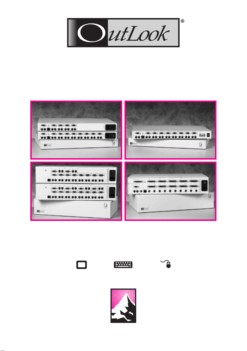
Apex PC Solutions offers the
OutLook
enable you to control large computer networks using a single
keyboard, monitor, and mouse. On
a single video screen, you can
select as many as 100 computers
running different operating systems. The OutLook switch patented
On-Screen Configuration and
Activity Reporting (OSCAR)
interface has intuitive menus for
accessing each attached computer.
Computers can be identified by
name or number, enabling you to
view and select server names that
make sense to you.
A typical OutLook switch system
consists of the console (monitor,
keyboard, and mouse), the switch
unit, and the attached computers.
You can choose from a single-user
system or a multiple-user system.
The OutLook family includes
switches specifically designed for
use in telecommunications systems,
financial and trading applications,
and Sun/Unix networks. Additional
OutLook switches can be connected
to the primary OutLook switch,
called tiering, to increase computer
access from 4, 8, or 10 computers
® family of switches to
Overview
Features
Illustrations of Switch Systems
Model Comparison Chart
to as many as 16, 64, or 100
computers. Tiering allows you to
modify your OutLook switch
system, as your network system
needs change.
Switching between computers is
accomplished by typing a command at the keyboard. The selected
computer receives characters typed
at the keyboard and displays its
video output on the monitor. You
can also use the mouse to interact
with the graphic interface of the
selected computer.
The OutLook family of products is
available in 4, 8, and 10-port
versions and can be used in various
configurations to accommodate
large or small systems. All versions
are packaged in space-efficient 1-U
height (1.75-in) or 2-U (3.5-in)
cases for desktop or rack-mounted
systems.
Overview
9
Page 10

FEATURES
1 Introduction
Compatible with major computer
and peripheral devices, including:
• Industry standard PS/2 mouse
and keyboard
• RS/6000 keyboard and mouse
• Computers requiring serial
pointing devices
(Via the Apex PS/2-to-serial port
converter)
• Sun Microsystems workstations
Offers customization and
adaptability to network needs
• Flexible configurations for a
variety of networks
• Adapts easily to changing
network needs
• Integrates computers running
Features
diffferent operating systems
Support standard display
converters and high-resolution
video, specifically:
• Analog VGA, SVGA, and XGA
video
• Maximum resolution of 1024 x
768 for video with a 25-ft video
cable, except for EL-100DT
which has a maximum resolution of 1600 x1200 with a 12-ft
video cable.
Ease of Use and Maintenance
• On-Screen Configuration and
Activity Reporting (OSCAR)
OSCAR displays system-related
information on the monitor,
including power-up test data and
configuration menus.
• Programmable scanning
Lets you observe system default
performance by automatically
switching computers in sequence, or you can set the
sequence and duration for each
computer in the system.
• Nonvolatile memory
Stores system settings and
display options even if the unit
is turned off or unplugged.
• External reset switch
Reinitializes attached devices
without interrupting power to
the system
• External keypad
Can take the place of the
keyboard for switching between
computers.
• Password security feature
Protects network resources by
locking the keyboard and
monitor.
• Sun, RS/6000, HP 9000, and
Apple Macintosh video (using
converters purchased separately).
10
Page 11
APEX OUTLOOK SWITCHES
ILLUSTRATIONS OF SWITCH SYSTEMS
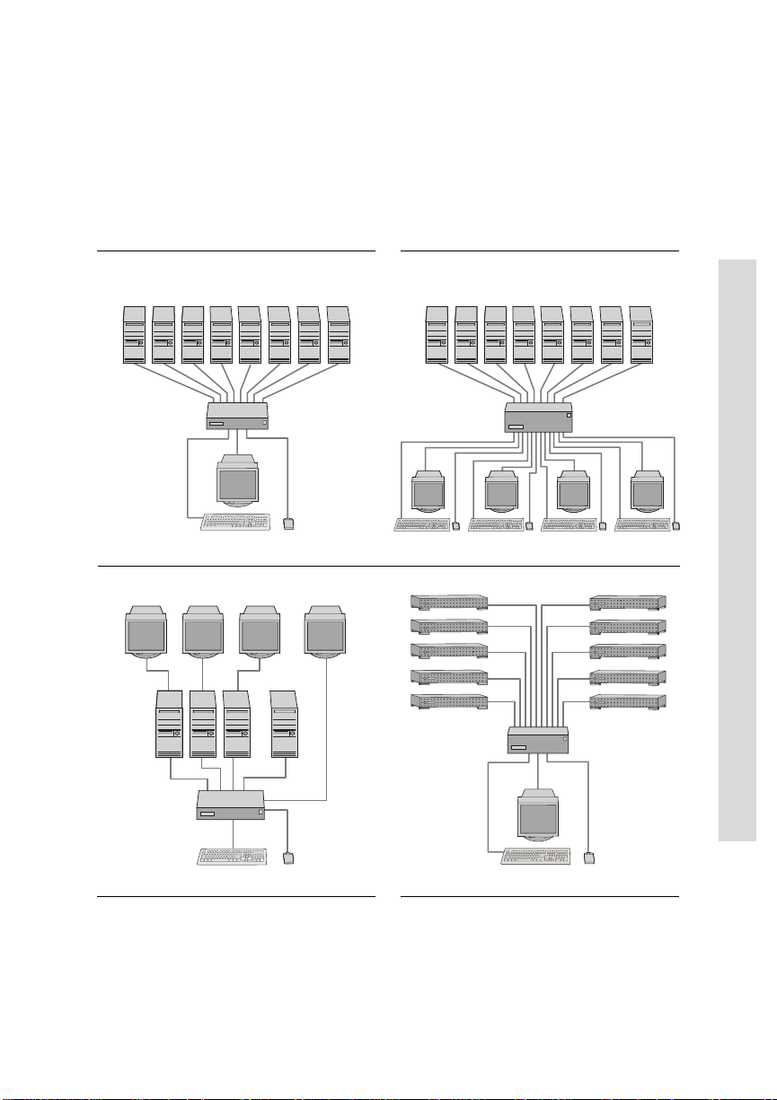
Single-Switch Systems
Single-user units connecting 4 or 8
computers. Access up to 64 computers
in tiered configurations.
Multiple-user units allowing 2 or 4
users to select up to 8 computers.
Access up to 64 computers in tiered
configurations.
EL-40DT and EL-80DT
EL-280DT and EL-480DT
Illustrations of Switch Systems
EL-80DFT
Single-user unit connecting 8
computers with only keyboard and
mouse switching. Designed for
financial and trading applications.
EL-100DT
Single-user unit connecting up to 10
computers. Access up to 100 Sun
computers in tiered configurations.
Designed for SunUnix networks.
11
Page 12
1 Introduction
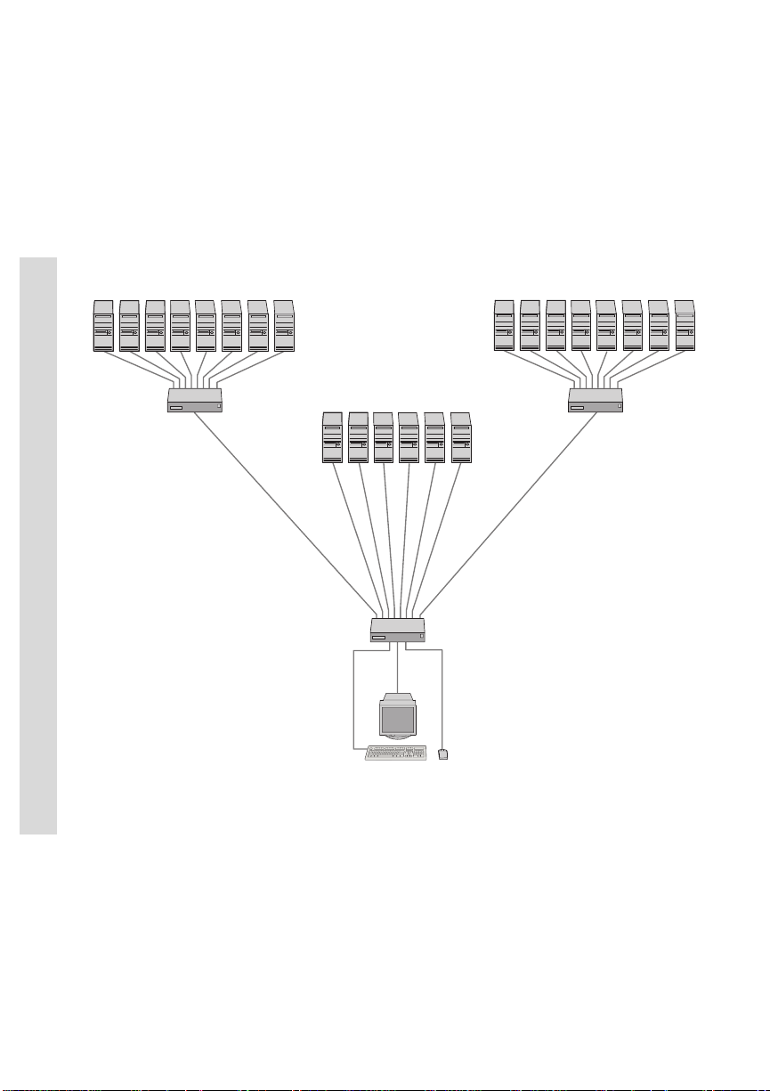
Multiple-Switch or Tiered System
This sample tiered configuration shows
the EL-80DT switch connected to two
secondary EL-80DT switches.
Illustrations of Switch Systems
12
Page 13

MODEL COMPARISON CHART
Power supply
110/220V AC 110/220V AC 110/220V AC 110/220V AC 48V DC 110/220V AC 110/220V AC
Specific system environment
no no Financial SunUnix Telecom no no
& trading systems
Switch connection mode control
no no no no no yes yes
Switches keyboard, video, mouse
yes yes K & M yes yes yes yes
only
APEX OUTLOOK SWITCHES
Number of tiered computers
32 64 64 100 64 64 64
Number of consoles (monitor, keyboard, mouse)
11K & M1124
only
Number of computer ports
48810888
EL-40DT EL-80DT EL-80DTF EL-100DT EL-80DC EL-280DT EL-480DT
Model Comparison Chart
13
Page 14

1 Introduction
14
Page 15

APEX OUTLOOK SWITCHES
INSTALLATION
2
INSTALLATION CHECK LIST
Your OutLook switch package contains
• The OutLook switch main unit
• Its power cord
(not included with EL-80DC)
• This User Guide
• A warranty card
You need to provide
• Interconnecting cables for
video, keyboard, and mouse
Interconnecting and extension
cables may be purchased
separately from Apex.(see
Appendix B Options and
Accessories)
• Your monitor, keyboard, and
mouse for each user console
• Your computers
Installation Checklist
Connecting the Console
Connecting the Primary Switch to a
Secondary Switch (Tiering)
Connecting the Computers
Turning On the System
Installation Checklist
Save your OutLook switch package
Apex ships the OutLook switch in
packaging designed to protect the
system during shipping and
handling. We recommend that you
save the carton and packing
materials until your equipment is
fully installed and operational.
If you should find that anything is
missing or arrived damaged, please
contact Apex PC Technical Support.
If you do need to return the
product, you must get an authorization number from technical
support. Apex PC Solutions will not
accept any returned materials
without first issuing a return
materials authorization number.
15
Page 16

2 Installation
Select switch connection mode for EL-280DT/EL-480DT
If you have purchased the multiple
user system EL-280DT or EL-480DT,
you must choose which switch
connection mode you perfer, either
cooperative or preemptive. Both
models ship with the factorydefault “cooperative” switch
connection mode. Cooperative
switching maintains established
port connections. If another
console attempts to select that port,
the request is denied. If you want
to change the default setting to
have the switch favor new connections, you need to move the DIP
switch 1 to the “preemptive”
setting. For additional information
and instructions, see Appendix G,
Setting DIP Switches.
Installation Checklist
Select location for the OutLook switch
OutLook switches can be used in
desktop or rackmounted systems.
Rackmount kits are available from
Apex PC Solutions if you would
like to mount your switch in an
EIA-standard 19-inch equipment
rack. Contact your Apex sales
representative for more information
regarding rackmount kits for
specific computers. See Appendix F
for instructions for mounting
brackets that fit EIA-standard
equipment racks.
Maximum Cable Length Distance
for Components
12 ft console to switch
50 ft computer to switch
50 ft switch to switch
Cable length affects video quality as
well as keyboard and mouse data
timing. The maximum length is
determined in part by the computer
and peripherals used. Not all systems
will give satisfactory results at the
maximum length.
16
Page 17

CONNECTING THE CONSOLE
APEX OUTLOOK SWITCHES
Standard connection
The console consists of the
keyboard, mouse or other pointing
device, and the monitor. The
keyboard and mouse connections
on the back panel of the switch
are 6-pin mini-DIN PS/2 style. The
video connection is HD15-pin
VGA/SVGA style. If the cables on
your keyboard, mouse, or monitor
require different connectors, you
can obtain a converter from Apex
(see Appendix B Options and
Accessories) or from the manufacturer of the device.
Special connections
The EL-100DT OutLook switch
You will need a video cable with
HD13W3 connectors and a keyboard cable with 8-pin mini-DIN
connectors for each computer.
(see Appendix B for cable kits)
IBM RS/6000 and HP 9000
Workstations
When connecting workstations
that use the “composite sync on
green” video option, you must use
the Apex video sync converter
(see Appendix B Options and
Accessories), which converts video
transmission to the more common
“separate sync” and improves
color balance. The video sync
converter must be connected to
both the keyboard and video
cables between the switch and
the workstation.
Sun Microsystems Workstations
Use the Apex Sun-to-PC keyboard
and mouse converter (see Appen-
dix B Options and Accessories) to
convert the video and keyboard
signals from the Sun Microsystems
workstation to PC-compatible
signals. The converter must be
connected to both the keyboard
and video cables between the
switch and the workstation. This
converter is not needed for the
OutLook EL-100DT switch.
Connecting the Console
Remote connection
Systems with External Keypad
The optional Apex external keypad
(see Appendix B Options and
Accessories) allows remote operation of the OutLook switch without
access to the keyboard. The keypad
cable terminates with an RJ45
modular plug that is connected to
the AUX jack on the back panel of
the switch.
17
Page 18

2 Installation
Sequence of cable connection
You should connect the cables to
the switch in this order:
1 mouse
2 video
3 keyboard
This cable connection sequence is
particularly important later when
you install new devices to your
OutLook system. You can connect a
mouse and/or keyboard to the
OutLook switch when the system is
running. When you connect the
new device, the switch recognizes
the device and configures it to the
settings of the currently selected
computer. This allows you to replace
failed devices without having to
restart the system.
Required Connectors for Switch
ALL MODELS EXCEPT EL-100DT
Mouse 6-pin mini-DIN PS/2 style
Keyboard 6-pin mini-DIN PS/2 style
Monitor HD15-pin VGA/SVGA style
EL-100DT ONLY
If attaching Sun console
Mouse/
Keyboard 8-pin mini-DIN
Monitor HD13W3
If attaching PC console*
Mouse 6-pin mini-DIN PS/2 style
Keyboard 6-pin mini-DIN PS/2 style
Monitor HD15-pin VGA/SVGA style
Save the hardware settings
when you make changes
Whenever you make changes to the
switch system, you should save the
hardware configuration settings. If
you do not save the settings, they will
be lost when power is lost or turned
Connecting the Console
off. To reestablish keyboard and
mouse communication to the switch,
you might have to reboot each computer . For procedure, see in Chapter 3,
Saving the Hardware Settings.
Outlined symbols represent jacks for interconnecting cables
Solid-colored symbols represent jacks for attaching physical devices
*(see table, Enabling Alternate
Connection on EL-100DT, later in this
section)
Maximum Cable Length Distance
for Console
ALL MODELS
12 ft keyboard, monitor, and
If you need longer than 12 foot
connections, contact your Apex sales
representative for information about
SwitchBack®.
mouse extension cables for
console connection
18
Page 19
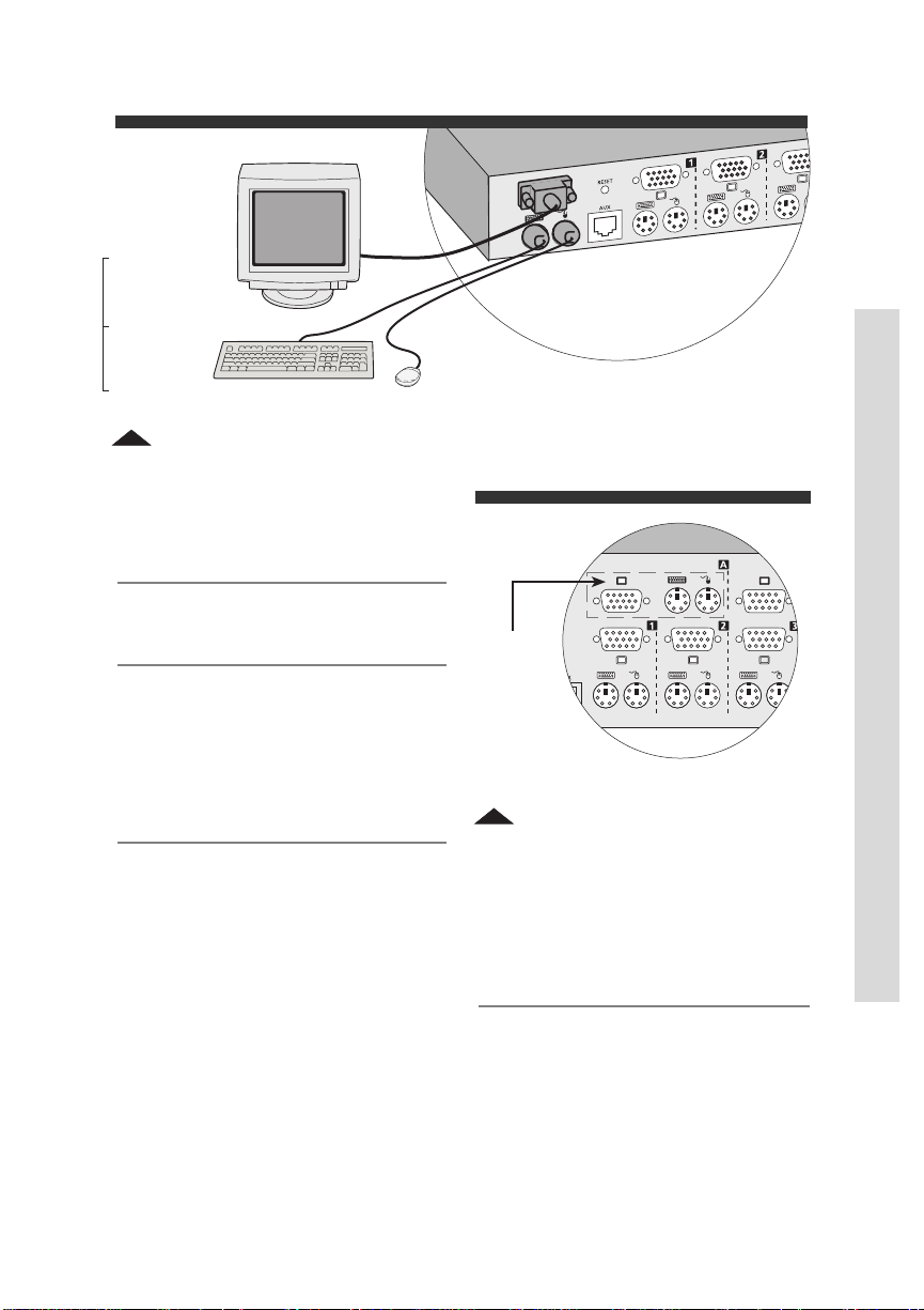
APEX OUTLOOK SWITCHES
Console
Monitor
Keyboard
Mouse
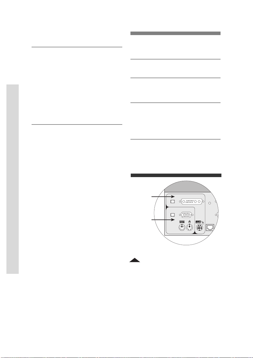
1 Console connection for EL-40DT/EL-80DT, EL-80DTF, EL-80DC
To connect the console:
1 Make sure the OutLook switch
is turned off and unplugged.
2 Place the switch in the desired
location. The maximum
distance the console can be
from the switch is 12 feet. If
Console
jacks for
attaching
monitor,
keyboard,
and mouse
rackmounting see Appendix F
for instructions.
2 Console connection for
3 Locate your model number
EL-280DT/EL-480DT
below for procedure on connecting the console. When you
have completed step 4, you can
skip the next section and go to
section Connecting the Comput-
MODELS EL-40DT/EL-80DT
EL-80DTF, EL-80DC
(refer to fig. 1)
ers if you are not tiering
computers.
4 Connect the mouse, monitor,
and keyboard cables to their
respective jacks on the back
panel of the switch.
Connecting the Console
19
Page 20
2 Installation
Sun Console Connection
Alternate Connection
Reset
Aux
Ke
MODELS EL-280DT/EL-480DT
(refer to fig. 2)
4 On the back panel of the switch
locate the keyboard, mouse,
and monitor jacks grouped by
labels, for example A, B, etc.,
and connect the mouse,
monitor, and keyboard cables to
their respective jacks.
Enabling Alternate Connection on
EL-100DT
FOR ATTACHING A PC CONSOLE
1 Unplug the power cable, if it is
connected, from the switch.
2 Remove the two screws holding the
access cover on the bottom of the
unit.
MODEL EL-100DT
(refer to fig. 3)
4 You have the option of attach-
ing a Sun console or a PC
console. The PC console
connects to the Alternate
Connection jacks. Enabling one
set of console jacks disables the
other set. If you wish to
connect a PC console then you
must move its DIP switch. If
you are tiering an EL-100DT
switch from a primary switch
that has a PC console attached,
then you must move the switch
Connecting the Console
to enable Alternate Connection.
For the procedure see table
Enabling Alternate Connection
on EL-1 00DT.
To attach a Sun console:
Connect the monitor and
keyboard cables to its respective jacks in the “Sun Console
Connection” on the back panel
of the switch.
To attach a PC console:
Connect the mouse, monitor,
and keyboard cables to their
respective jacks in the Alternate
Connection area on the back
panel of the switch.
3 Inside the unit, set switch 1-1 to the
On position to enable the Alternate
Connection jacks, the Off position
to enable the Sun Console
Connection jacks.
4 Replace the access cover.
Sun
console
PC
console
3 Console connection for EL-100DT
20
Page 21

APEX OUTLOOK SWITCHES
CONNECTING THE PRIMARY SWITCH TO A SECONDARY SWITCH (TIERING)
Tiered configurations
Multi-switch systems or tiered
configurations allow the greatest
flexibility and capacity. In a tiered
system, the OutLook switch
connected to the console becomes
the “primary” switch. Tiers consist
of one or more “secondary”
OutLook switches, which are
connected to the computer ports on
the primary switch. One 8-port
primary unit can accommodate
eight secondary switches and
access up to 64 servers. One 10-port
primary unit can accommodate ten
secondary switches and access up
to 100 servers.
Adding a secondary switch while the system is running
If you are installing a secondary
switch to an existing OutLook
switch system, you can attach the
secondary switch while the system
is running. To do this, you must
first connect the mouse and video
cables, then the keyboard cable.
When you power on the secondary
switch, the keyboard connection
sends data to the primary switch
allowing the secondary switch to
boot up.
Whenever you add new devices to
the system, you have to let the
OutLook switch know you added
an additional device. For procedure
see Saving the Hardware Settings in
Chapter 3.
Port numbering scheme
Secondary computer ports have a
different numbering scheme from
the primary computer ports. The
port numbering scheme for the
primary switch is Port 1, Port 2,
Port 3, etc. The numbering scheme
for the secondary switch is the
number of the port on the primary
switch followed by a dash, then the
number of the port on the secondary switch. For example, a secondary switch connected to Port 2 on
the primary switch has the number
Port 2-1. Other ports on the secondary unit would be Port 2-2, Port 2-3,
Port 2-4, etc. You can assign names
to computers. For procedure see in
Chapter 3 Assigning Unique Names
to Computers.
Required Connectors for Switch
ALL MODELS EXCEPT EL-100DT
Mouse 6-pin mini-DIN PS/2 style
Keyboard 6-pin mini-DIN PS/2 style
Monitor HD15-pin VGA/SVGA style
EL-100DT ONLY
Mouse/
Keyboard 8-pin mini-DIN
Monitor HD13W3
Connecting the Primary Switch to a Secondary Switch
21
Page 22

2 Installation
Maximum Cable Length Distance
50 ft switch to switch
50 ft switch to computer
Cable length affects video quality as
well as keyboard and mouse data
timing. The maximum length is
determined in part by the computer
and peripherals used. Not all systems
will give satisfactory results at the
maximum length.
To connect a secondary
switch to a primary switch:
MODELS EL-40DT/EL-80DT,
EL-80DTF, EL-80DC
Refer to fig. 4
MODELS EL-280DT/EL-480DT
Refer to fig. 5
4 For EL-40DT/EL-80DT,
EL-80DTF, EL-80DC
On the far left side of the back
panel of the secondary switch,
connect the video, mouse, and
keyboard interconnecting
cables to their respective
console jacks.
—or—
1 Make sure the secondary
OutLook switch is turned off
and unplugged.
For EL-280DT/EL-480DT
On the far left side of the back
panel of the secondary switch,
connect the video, mouse, and
keyboard interconnecting
2 Place the secondary switch in
the desired location. The
cables to their respective jacks
in console “A.”
maximum distance a secondary
switch can be from the primary
unit and computers is 50 feet. If
rackmounting see Appendix F
for instructions.
5 On the back panel of the
primary switch, connect the
other end of the video and
mouse cables to their respective
jacks beneath one of the
3 Locate your model number
numbered port labels.
below for procedure on connecting a secondary switch.
6 Connect the other end of the
keyboard cable to its respective
Connecting the Primary Switch to a Secondary Switch
jack in the same port.
7 Bundle and label cables for
easy identification.
8 Connect the power cord to the
switch.
22
Page 23

APEX OUTLOOK SWITCHES
RESET
RESET
secondary
primary
4 Tiered switch connection for EL-40DT/EL-80DT, EL-80DTF, EL-80DC
video,
mouse, and
keyboard
cables
Your
monitor,
keyboard,
and mouse
secondary
Connecting the Primary Switch to a Secondary Switch
primary
5 Tiered switch connection for EL-280DT/EL-480DT
23
Page 24

2 Installation
Sun Console Connection
Alternate Connection
Reset
Aux
Video
One
Video
Two
Keyboard
One
Keyboard
Two
Sun Console Connection
Alternate Connection
Reset
Aux
Video
One
Video
Two
Keyboard
One
Keyboard
Two
Sun Console Connection
Alternate Connection
Reset
Aux
Video
One
Video
Two
Keyboard
One
Keyboard
Two
EL-100DT
video cable
keyboard cable
6 Tiered Sun Configuration for EL-100DT
secondary EL-100DT
primary EL-100DT
secondary EL-100DT
primary EL-80DT
video,
keyboard, and
mouse cables
Connecting the Primary Switch to a Secondary Switch
7 Tiered PC/Sun Configuration for EL-100DT
24
Page 25

APEX OUTLOOK SWITCHES
MODEL EL-100DT
For an EL-100DT to another
EL-100DT switch with a Sun console
(refer to fig. 6)
4 On the far left side of the back
panel of the secondary switch,
connect the video and keyboard
interconnecting cables to their
respective jacks on the Sun
Console Connection.
5 On the back panel of the
primary switch select one of the
available computer ports to
connect the other end of the
video and keyboard cables to
their respective jacks.
6 Bundle and label cables for
easy identification.
7 Connect the power cord to the
switch.
For an EL-100DT to a primary
switch, such as an EL-80DT
with a PC console
(refer to fig. 7)
procedure, see table Enabling
Alternate Connection on
EL-100DT in previous section,
Connecting the Console, for
model EL-100DT. Then proceed
to step 5.
5 On the far left side of the back
panel of the EL-100DT switch,
connect the video, mouse, and
keyboard interconnecting cables
to their respective jacks in
Alternate Connection.
6 On the back panel of the
primary switch, connect the
other end of the video cable to
the HD15-pin VGA jack beneath
one of the numbered port
labels. Under the same port
label connect the mouse cable
to its respective jack.
7 Connect the other end of the
keyboard cable to its respective
jack in the same port label as
step 6.
8 Bundle and label cables for
easy identification.
Connecting the Primary Switch to a Secondary Switch
4 If you are integrating both PC
and Sun computers, you must
enable the Alternate Connection
jacks. To do this, you must
move the DIP switch. For
9 Connect the power cord to the
switch.
25
Page 26

2 Installation
CONNECTING THE COMPUTERS
Required Connectors for Switch
ALL MODELS EXCEPT EL-100DT
Mouse 6-pin mini-DIN PS/2 style,
Keyboard 6-pin mini-DIN PS/2 style,
Video HD15-pin VGA/SVGA style,
EL-100DT ONLY
Mouse/
Keyboard 8-pin mini-DIN, male
Video HD13W3, male
Maximum Cable Length Distance
50 ft switch to computer
Cable length affects video quality as
well as keyboard and mouse data
timing. The maximum length is
Connecting the Computers
determined in part by the computer
and peripherals used. Not all systems
will give satisfactory results at the
maximum length.
If your computer has a different
keyboard or mouse connector, you
can obtain a converter from Apex
(see Appendix B Options and
Accessories) or from the manufac-
male
male
male
turer of the device. Any graphics
system that uses sync on green
requires a video converter. A
variety of other video converters
are also available. (contact Apex PC
Solutions Technical Support for
help) See Appendix E for diagrams
of monitor, keyboard, and mouse
connector pin specifications.
Adding a computer while the system is running
If you are installing a computer to
an existing OutLook switch system,
you can attach the computer while
the system is running. To do this,
you must first connect the mouse
and video cables, then the keyboard cable. When you power on
the computer, the keyboard connection sends data to the switch,
allowing the computer to boot up.
Save the hardware settings
when you make changes
Whenever you make changes to the
switch system, you should save the
hardware configuration settings. If
you do not save the settings, they will
be lost when power is lost or turned
off to the switch, and you might have
to reboot each computer to reestablish keyboard and mouse communication. For procedure see in Chapter 3,
Saving the Hardware Settings.
Outlined symbols represent jacks for interconnecting cables
Solid-colored symbols represent jacks for attaching physical devices
26
Page 27

APEX OUTLOOK SWITCHES
8 Computer connection for EL-40DT/EL-80DT, EL-80DC
To connect a computer to the
OutLook switch:
MODELS EL-40DT/EL-80DT,
1 Make sure the computer is
turned off and unplugged.
2 Place the computer in the
EL-80DC
(refer to fig. 8)
MODELS EL-280DT/EL-480DT
(refer to fig. 9)
desired location. Maximum
distance a computer can be
from the switch is 50 feet. If
rackmounting see Appendix F
for information.
4 Connect video, mouse, and
keyboard cables to their
respective jacks on the computer.
Connecting the Computers
3 Locate your model number
below for procedure on connecting a computer.
5 On the back panel of the switch
in one of the numbered ports,
connect the mouse and video
cables to their respective jacks.
6 Connect the keyboard cable to
its respective jack in the same
numbered port as step 5.
27
Page 28

2 Installation
7 Repeat steps 4–6 for additional
computers. Bundle and label
the cables for easy identification.
8 Connect the power cord to the
switch.
MODEL EL-80DTF
(refer to fig. 10)
4 Connect mouse, keyboard, and
video cables to their respective
jacks on the computer.
5 Determine which computer to
connect to Port 1. Locate Port 1
on the back panel of the switch.
Connect the other end of the
video, mouse, and keyboard
cables to their respective jacks.
6 For additional computers,
connect the mouse and keyboard cables to their respective
jacks in Ports 2–8. Connect the
Connecting the Computers
video cable of the computer
directly to the video jack on the
monitor. It does not connect to
the switch.
7 Bundle and label the cables for
easy identification.
8 Connect the power cord to the
switch.
Port 1 jacks
for attaching
video,
keyboard,
and mouse
computer
cables
9 Computer connection for
EL-280DT/EL-480DT
Port 1 jacks
for attaching
video,
keyboard,
and mouse
computer
cables
10 Computer connection for
EL-80DTF
28
Page 29

MODEL EL-100DT
Reset
Aux
Video
One
Video
Two
Keyboard
One
Video
Three
Video
Four
Keyboard
Two
Keyboard
Three
Keyboard
Four
(refer to fig. 11)
4 Connect the video and key-
board cables to their respective
ports on the computer.
5 Determine which computer to
connect to Port 1. Connect the
other end of the video and
keyboard cables to their
respective jacks labeled “Video
One” and “Keyboard One” on
the switch.
6 Repeat steps 4 and 5 for
connecting additional computers. Bundle and label the cables
for easy identification.
7 Connect the power cord to the
switch.
APEX OUTLOOK SWITCHES
Port 1 jacks
for attaching
keyboard
and video
computer
cables
11 Computer connection for
EL-100DT
Connecting the Computers
29
Page 30

2 Installation
TURNING ON THE SYSTEM
Startup sequence
When a computer boots up, the
attached keyboard, mouse, and
monitor send device configuration/
commands settings out of the
computer port. The OutLook switch
stores these device settings. If the
switch is turned on before the
computers, the OutLook switch can
boot up computers that do not have
physically connected to them, a
keyboard, monitor, or mouse. If the
computers are turned on before the
OutLook switch, the computers will
probably either hang, crash, or
exhibit abnormal behavior because
the computers need the keyboard,
mouse, and monitor device configuration/commands settings in
order to boot properly. For your
switch system to work, the switch
must be turned on before the
computers.
Startup behavior
Turning On the System
When you turn on the switch, it
performs the following actions:
• Identifies the mouse and keyboard and puts them into default
states.
• Displays copyright information
about the OutLook switch and
firmware.
• Selects Port 1 and displays the
number 1 in the status flag on
the monitor as shown here.
1
—or—
If you have models EL-280DT/
EL-480DT, selects Port 0 and
displays the number 0 in the
status flag instead of number 1.
If the copyright information and
status flag do not appear on the
monitor, make sure that the
monitor is connected and turned on.
OutLook switch behavior with
power outages
The OutLook switch system will help
your computers recover from power
outages. After a power outage, each
computer connected to the switch
reboots (if designed to do so) automatically when power is restored. The
switch generates responses to ensure
that the reboot is successful and that
the switch is ready to select computers when regular operation resumes.
If you are using an uniterrupted
power supply, connect the switches
to the same power source as the rest
of the system.
30
Page 31

To start the system:
1 Plug in the power cord.
2 Turn on the monitor according
to the manufacturer’s instructions.
3 Turn on the switch by pressing
the power switch located on the
back panel to the On (|)
position.
4 Turn on the computers accord-
ing to the manufacturer’s
instructions.
5 From the console press
<PRINT SCREEN> to open
OSCAR menus and then
<F2>;
OSCAR Advanced Menus screen
appears.
APEX OUTLOOK SWITCHES
Turning On the System
6 Highlight Snapshot and press
<ENTER> to save the hardware
settings, used when the switch
reinitializes. (For more information see in Chapter 3 the
procedure Saving the Hardware
Settings.)
7 If you have a tiered configuration
Designate that the numbered
port is connected to a secondary switch rather than a
computer by performing the
procedure Assigning Specific
Device Types. You will find the
procedure in Chapter 3.
31
Page 32

2 Installation
32
Page 33

APEX OUTLOOK SWITCHES
OPERATION GUIDE
3
NAVIGATING WITH OSCAR
Operate with keyboard and mouse
OSCAR, On-Screen Configuration
and Activity Reporting, is the
interface you use to communicate
with the OutLook switch. You’ll
navigate the OSCAR menus and
enter commands using the mouse
and keyboard; however, because
the switch operates independently
of the computer operating systems,
OSCAR keyboard and mouse
conventions may differ from those
you use when controlling the
selected computer. See the following table, Keyboard Conventions for
OSCAR Menus, for keyboard
sequences used to navigate OSCAR.
Navigating with OSCAR
Selecting Computers
Assigning Unique Names to Computers
Changing Menu Attributes
Changing Status Flag Attributes
Scanning the Computers
Broadcasting Commands
Securing Server Access
Displaying Version Information
Saving the Hardware Settings
Resetting the Mouse and Keyboard
Assigning Specific Device Types
Adjusting the Video Impedance Value
Navigating with OSCAR
33
Page 34

3 Operation
Keyboard Conventions for OSCAR Menus
THIS KEY DOES THIS
PRINT SCREEN Opens OSCAR Selection screen. (To print a screen, see
in this section the procedure To conduct a screen
capture.)
F2 When in OSCAR Selection screen, opens OSCAR
Advanced Menus screen.
ARROWS Moves highlight to select command feature or setup.
+/– Changes the value of the selected option.
ENTER Saves current settings or changes and returns to
OSCAR Advanced Menus screen.
ESCAPE Cancels unsaved changes and returns to OSCAR
NUMERIC KEYPAD Always in the numeric state, although the indicator on
CAPS LOCK Disabled. (Use the SHIFT key to change case.)
Advanced Menus screen. When in OSCAR Selection or
Advanced Menus screens, ESCAPE exits OSCAR.
the keyboard may indicate otherwise.
Navigating with OSCAR
Once OSCAR is activated, you can
use the mouse instead of the arrow
keys to highlight menu options. Use
the left mouse button as you would
the
ENTER key, to select menu
options and move between data
entry fields. Use the right mouse
button as you would the
key, to cancel an entry and return
to the previous screen.
ESCAPE
34
Page 35

APEX OUTLOOK SWITCHES
Using the Print Screen key
In the Outlook switch system
pressing the
PRINT SCREEN key
opens the OSCAR Menus. If you
want to print a screen capture
displayed by a computer, follow
this procedure:
To conduct a screen capture:
● On a computer connected to a
primary OutLook switch
press
PRINT SCREEN twice.
The first keystroke opens
OSCAR menus in the primary
switch. The second keystroke
clears the screen, then captures
or prints the screen.
● On a computer connected to a
secondary OutLook switch in a
tiered configuration, press
PRINT SCREEN 4 times.
The first keystroke brings up
OSCAR in the primary switch.
The second keystroke brings up
OSCAR in the secondary
switch. The third keystroke
brings up both OSCARs. The
fourth keystroke clears the
screen, then captures or prints
the screen.
OSCAR Selection screen
When you press the PRINT SCREEN
key to open the OSCAR menus, the
first screen that appears is called
the OSCAR Selection screen (see
the following procedure for illustration of screen). Basic functions
such as selecting computers and
checking port/computer status are
performed from the OSCAR Selection screen.
The OSCAR Selection lists all the
ports in the system, the associated
computer names, and the status of
each port (see following table
OSCAR Status Port Symbols). It can
be organized either by port number
or by computer name. To identify
your computers by name see
procedure Assigning Unique Names
to Computers. To change the order
in which computers are listed, see
the procedure Changing Menu
Attributes. On large systems, you
may need to use the
or the
PAGE DOWN key to scroll
ARROW keys
through the list of ports.
Navigating with OSCAR
35
Page 36

3 Operation
To open OSCAR or access the
OSCAR Selection screen on a
primary switch:
● Press <PRINT SCREEN> once.
All naming, scanning, status flag
attributes, OSCAR attributes, device
settings, passwords, etc. must be
set at the primary switch.
OSCAR SELECTION
Port Name
1 COMPUTER 1
2 COMPUTER 2 +
3 COMPUTER 3 +
4 COMPUTER 4
5 COMPUTER 5 +
6 COMPUTER 6
7 COMPUTER 7 +
8 COMPUTER 8
F1 Help F2 Advanced
If your primary switch has
secondary switches connected
to it, the OSCAR Selection
screen shows a different portnumbering scheme. The
numbering scheme for the
Navigating with OSCAR
secondary switch is the
number of the port on the
primary switch followed by a
dash, then the number of the
port on the secondary switch.
To open OSCAR or access the
OSCAR Selection screen on a
secondary switch:
1 Press <PRINT SCREEN> to
access OSCAR Selection screen
at the primary switch.
2 Hightlight the number of the
port to which you want to
access. Press
<PRINT SCREEN>;
OSCAR Selection at the secondary switch appears.
The factory defaults for OSCAR
should not be changed in a secondary switch because adjustments
can cause conflicts between the
secondary and the primary switch.
OSCAR Status Port Symbols
+ Computer connected and running.
x Secondary switch connected and
running.
OSCAR SELECTION
Port Name
1–1 COMPUTER 1 x
1–2 COMPUTER 2 x
1–3 COMPUTER 3 x
1–4 COMPUTER 4 x
1–5 COMPUTER 5 x
1–6 COMPUTER 6
1–7 COMPUTER 7 x
1–8 COMPUTER 8
F1 Help F2 Advanced
■ Note
The OSCAR screens in this User Guide
show the default screens of model
EL-80DT. Your screens will show the
OSCAR features and the computer
names and port numbers associated
with your particular OutLook switch
system.
36
Page 37

APEX OUTLOOK SWITCHES
OSCAR Advanced Menus screen
All commands other than selecting
computers are performed from the
OSCAR Advanced Menus. The
Advanced Menus screen contains
two menus. The Commands menu
shows the commands that cause an
action to take place. The Setup
menu shows the commands that
have screens to set configurations.
To open the OSCAR Advanced
Menus:
1 Press <PRINT SCREEN> to open
OSCAR Selection.
2 Press <F2>.
The OSCAR Advanced Menus
screen appears showing the
commands listed under the Commands menu. Highlighting Setup
shows the commands listed under
the Setup menu. Moving the
highlight with the arrow keys or
mouse in either menu selects a
command.
To exit OSCAR:
● Press <ESCAPE>.
Navigating with OSCAR
OSCAR ADVANCED MENUS
COMMANDS
Scan
Version
Snapshot
Reset
Broadcast
SETUP
OSCAR ADVANCED MENUS
COMMANDS SETUP
Scan
Names
OSCAR
Flag
Devices
Security
Broadcast
37
Page 38

3 Operation
SELECTING COMPUTERS
Use the OSCAR menus to switch
computers, that is, to select which
computer receives commands from
and displays output to the console.
When you select a computer, the
OutLook switch reconfigures the
keyboard and mouse for the
selected computer using the
settings stored in its memory. In
this way OutLook maintains
current information, (e.g., the state
of the
CAPS LOCK key) for each
computer in the system. When
configuration is complete, the video
output of the selected computer
passes to the monitor.
To switch computers:
1 If your computers are ordered
by the number of the port, in
the OSCAR Selection screen
type the port number of the
Selecting Computers
computer you want to switch
to.
—or—
Use the arrow keys or mouse to
select a computer.
OSCAR SELECTION
Port Name
1 COMPUTER 1
2 COMPUTER 2 +
3 COMPUTER 3 +
4 COMPUTER 4
5 COMPUTER 5 +
6 COMPUTER 6
7 COMPUTER 7 +
8 COMPUTER 8
F1 Help F2 Advanced
2 Press <ENTER>.
3 When you are finished switch-
ing, press
<ESC> to exit OSCAR
and remove the OSCAR menus
from your monitor display. If
the status flag is enabled, it will
remain displayed to indicate the
currently selected computer.
■ Note
Y our OSCAR Selection screen will look
different from the example above. It
will show the computer names and
port numbers assigned to your particular OutLook switch system.
—or—
If your computers are ordered
by name, type the first letters
of the computer name to
establish it as unique in order
to select it. To identify computers by name, see the procedure
Assigning Unique Names to
Computers.
38
Page 39

APEX OUTLOOK SWITCHES
ASSIGNING UNIQUE NAMES TO COMPUTERS
You may find it easier to identify
the computers in a system by
name, rather than by port number.
For example, in a network environment, you can assign the same
names as those assigned by the
network for each computer. To list
the computers by name in the
OSCAR menus, see the procedure
Changing Menu Attributes.
■ Note
Before you can assign names to computers attached to secondary switches,
you must first associate the secondary device with a port. See the procedure Assigning Specific Device Types
found later in this chapter.
To assign unique names to
computers:
1 In the Advanced Menus screen,
move the highlight to the Setup
menu.
2 Highlight Names and press
<ENTER>; the Port Name Setup
screen appears.
PORT NAME SETUP
Port Name
1 COMPUTER 1
2 COMPUTER 2
3 COMPUTER 3
4 COMPUTER 4
5 COMPUTER 5
6 COMPUTER 6
7 COMPUTER 7
8 COMPUTER 8
3 Select the port number for
which you want to enter or
change a computer name.
Assigning Unique Names to Computers
4 Type a name for the computer.
Computer names may be up to
12 characters long, including
only A–Z, 0–9, and the dash
character. Lowercase letters are
converted to uppercase. Press
<BACKSPACE> to delete an
incorrect entry.
5 If necessary, repeat steps 3 and
4 for each computer in the
system.
39
Page 40

3 Operation
CHANGING MENU ATTRIBUTES
In the OSCAR Attributes screen you
can change the order of computer
ports from displaying the number
to displaying the name of the port.
Other attributes of the OSCAR
screens, such as the position and
color, can be changed to suit the
particular use of the system.
To change menu attributes:
3 Highlight the setting(s) you
want to change and use the +
or – keys to obtain the desired
value. As you select different
values, the effect of the changes
is reflected immediately on the
display. The following table,
Effects of Settings on Screen
Appearance, describes each of
the available menu attributes.
1 In the Advanced Menus screen,
move the highlight to the Setup
menu.
2 Highlight OSCAR and press
<ENTER>; the OSCAR Attributes
screen appears.
OSCAR ATTRIBUTES
Resolution 320
Height 56
Horizontal 3
Vertical 4
Background 7
Changing Menu Attributes
Highlight 6
Text 0
Delay Time 0
Order PORT
■ Note
While changing OSCAR attributes, it
is possible to garble the menu and
screens, making it difficult to correct
the problem. If this occurs, you can
reset the switch to its default OSCAR
values by pressing:
<ESCAPE, ESCAPE, PRINT SCREEN, F10,
Y, ENTER>.
40
Page 41

Effects of Settings on Screen Appearance
SIHTEGNAHCOTGNITTESSIHTTCELESSEULAVESOOHC
APEX OUTLOOK SWITCHES
xetdnat
Tfognimi
RACSO
neercsfoeziS
txetfoeziS
neercsfonoitacoL
neercsforoloC
NOITULOSER
THGIEH
LATNOZIROH
LACITREV
DNUORGKCAB
THGILHGIH
TXET
EMITYALED
noitceleS
alpsidneercsy
sretupmocforedrO
REDRO
.txetdezisregral
0- 721
0- 552
0-7
0-7
0-7
RACSO
retfa
.snoitarepo
bahpla.emanybyllacite
ro,084,023rehtietceleS
,eulavehtrewoleht;046
.ezisehtregraleht
yalpsidseulavrehgiH
Changing Menu Attributes
ehtsdnocesniemiT
sineercsnoitceleS
gniraeppaerofebdeyaled
NEERCSTNIRP
si
yaledgnisaercnI.desserp
neercsehttneverpnac
noitcartsidagniebmorf
elpmisgnimrofrepnehw
gnihctiwsretupmoc
sretupmoctsilotesoohC
rorebmuntropyb
41
Page 42

3 Operation
CHANGING STATUS FLAG ATTRIBUTES
The status flag indicates the name
or port number of the currently
selected computer. You can choose
to display the status flag at all
times, for a few seconds after
switching, or not at all. You can
also change the color of the status
flag and its location on the screen.
To change status flag
attributes:
1 In the Advanced Menus screen,
move the highlight to the Setup
menu.
2 Highlight Flag and press
<ENTER>; the Flag Configura-
tion screen appears.
3 Highlight the setting you want
to change and use the + or –
keys to adjust the values. The
following table, Values and
Effects of Settings on Flag
Appearance, describes each of
the available menu attributes.
1
FLAG CONFIGURATION
Enabled PORTS ON
Row 14
Column 1
Color 2
Changing Status Flag Attributes
Text 0
Mode OPAQUE
42
Page 43

APEX OUTLOOK SWITCHES
Values and Effects of Settings on Flag Appearance
SETTING VALUES EFFECT
ENABLED Flag Off Flag does not appear.
Ports On Indicates selected port number.
Names On Indicates selected computer by name.
Ports Timed Port number displays for 5 seconds after
switching.
Names Timed Name displays for 5 seconds after switching.
ROW 0–14 Positions the flag vertically on the screen.
COLUMN 0–25 Positions the flag horizontally on the screen.
COLOR 0–7 Sets the flag color.
TEXT 0–7 Sets the flag text color.
MODE Opaque Makes flag opaque.
Transparent Makes flag transparent.
Changing Status Flag Attributes
43
Page 44

3 Operation
SCANNING THE COMPUTERS
In scan mode, the OutLook switch
automatically switches from port to
port (computer to computer). You
can scan the entire system sequentially or designate a custom scan
pattern by specifying computers
and durations.
To place the switch in scan
mode:
1 From the Commands menu in
the Advanced Menus screen,
move the highlight to Scan.
OSCAR ADVANCED MENUS
COMMANDS
Scan
Version
Snapshot
Reset
Broadcast
SETUP
Scanning the Computers
2 Press <ENTER>.
To set a custom scan patter n:
1 In the Advanced Menus screen,
move the highlight to the
Setup
menu.
OSCAR ADVANCED MENUS
COMMANDS SETUP
Scan
Names
OSCAR
Flag
Devices
Security
Broadcast
2 Highlight Scan and press
<ENTER>; the Scan Pattern
Setup screen appears with the
first port position (or computer
name) highlighted.
In the Scan Pattern Setup
screen shown, the order-byport mode is selected. Your
menu may appear different
(see the procedure Changing
Menu Attributes).
To cancel scan mode:
● Press any key (except PRINT
SCREEN
) or move the mouse;
the scan stops at the currently
selected computer.
SCAN PATTERN SETUP
Port Sec Name
6 20 COMPUTER 6
5 20 COMPUTER 5
4 10 COMPUTER 4
1 10 COMPUTER 1
F2 for defaults
44
Page 45

3 Type the port number of the
first computer to be included in
the scan.
—or—
If your computers are listed by
name, type the first few letters
of the name of the first computer to be included in the scan.
4 Move the highlight to the Sec
column, and then type the
number of seconds that you
want this computer to be
selected before switching to the
next computer in the sequence.
5 Move the highlight to the next
line and repeat steps 3 and 4
for each of the remaining
computers.
6 Press <ENTER> to save the
settings. The new scan pattern
replaces the standard or
previous custom scan pattern.
■ Note
Pressing ESCAPE at any time prior to
pressing ENTER retains the previous
scan pattern. To return all Port and
Sec values to factory defaults, press
<F2> while in the Scan Pattern Setup
screen.
APEX OUTLOOK SWITCHES
To remove a computer from
the scan list:
1 In the Scan Pattern Setup
screen, type the port number of
the computer to be removed.
—or—
If your computers are listed by
name, type the first few letters
of the name of the computer.
2 Move the highlight to the Sec
column.
3 Type 0 for the number of
seconds.
Pressing <
DELETE> (not the
DEL key on the numeric
keypad) while in the Scan
Pattern Setup screen deletes
the highlighted computer and
all entries below it.
4 Press <ENTER> to save the
settings. The new scan pattern
replaces the standard or
previous custom scan pattern.
Scanning the Computers
45
Page 46

3 Operation
BROADCASTING COMMANDS
FOR MODELS EL-40DT/EL-80DT,
EL-80DTF, EL-40DC/EL-80DC ONLY
The broadcast feature (OutLook
version 1.5.0 or later) enables you
to simultaneously control more
than one computer in a system.
This feature is useful when you
want to ensure that all selected
computers receive identical input.
For each computer receiving the
broadcast, you can choose to
broadcast keystrokes and/or mouse
movements independently.
■ Notes
For all computers receiving a broadcast to interpret commands identically ,
the keyboard and mouse states for the
computers must be identical. Specifically, the
modes should be the same on all keyboards. For the mouse to work accurately , all systems must have identical
mouse drivers, identical desktops, and
identical video resolutions. In addition,
the mouse must be in exactly the same
Broadcasting Commands
place on all screens. Because these
conditions are extremely difficult to
achieve, broadcasting mouse movement to multiple systems may have
unpredictable results.
OutLook attempts to send keystrokes
and mouse commands to the selected
computers simultaneously; however,
some computers may inhibit and thus
delay the transmission.
CAPS LOCK and NUMLOCK
To broadcast to selected
computers:
1 From the Setup menu in the
Advanced Menus screen,
highlight Broadcast and press
<ENTER>; the Broadcast Settings
menu appears.
OSCAR ADVANCED MENUS
COMMANDS SETUP
Scan
Names
OSCAR
Flag
Devices
Security
Broadcast
2 For each port select which
computers receive keyboard
and/or mouse commands by
using the + or – key to choose
YES or NO.
BROADCAST SETTINGS
Port Keyboard Mouse
1 YES YES
2NO NO
3 YES NO
4 YES YES
5NO NO
6 YES NO
7 YES YES
8 YES YES
When broadcast mode is on, its symbol appears in the status
flag as shown here.
46
Page 47

3 Press <ENTER> to save the
settings.
4 From the Commands menu in
the Advanced Menus screen,
highlight Broadcast. Press
<ENTER> to turn on the broad-
cast mode. Type information
and/or make mouse movements you want to broadcast.
OSCAR ADVANCED MENUS
COMMANDS
Scan
Version
Snapshot
Reset
Broadcast
SETUP
To turn off the broadcast
mode:
APEX OUTLOOK SWITCHES
Broadcasting to tiered configurations
In a tiered system you can broadcast to any combination of computers on the entire system.
To broadcast to tiered
configurations:
1 From the OSCAR Selection
screen at the primary switch,
highlight the port number of
the secondary switch (for
example, Port 1-1, 2-1, 3-1, etc)
to which you want to broadcast
commands; press
OSCAR SELECTION
Port Name
1–1 COMPUTER 1 x
1–2 COMPUTER 2 x
1–3 COMPUTER 3 x
1–4 COMPUTER 4 x
1–5 COMPUTER 5 x
1–6 COMPUTER 6 x
1–7 COMPUTER 7 x
1–8 COMPUTER 8 x
F1 Help F2 Advanced
<ENTER>.
Broadcasting Commands
● From the Commands menu in
the Advanced Menus, highlight
Broadcast and press
<ENTER>.
2 Press <PRINT SCREEN> twice;
the
OSCAR Selection screen of
the secondary switch appears.
Press
<F2> to access the
Advanced Menus screen.
OSCAR SELECTION
Port Name
1 COMPUTER 1 +
2 COMPUTER 2 +
3 COMPUTER 3 +
4 COMPUTER 4 +
5 COMPUTER 5 +
6 COMPUTER 6 +
7 COMPUTER 7 +
8 COMPUTER 8 +
F1 Help F2 Advanced
47
Page 48

3 Operation
3 From the Setup menu, highlight
Broadcast. Press
access the Broadcast Settings
menu.
OSCAR ADVANCED MENUS
COMMANDS SETUP
Scan
Names
OSCAR
Flag
Devices
Security
Broadcast
4 For each port select which
computers receive keyboard
and/or mouse commands by
using the + or – key to choose
YES or NO.
BROADCAST SETTINGS
Port Keyboard Mouse
1 YES YES
2NO NO
3 YES NO
4 YES YES
Broadcasting Commands
5NO NO
6 YES NO
7 YES YES
8 YES YES
<ENTER> to
7 Repeat steps 1–6 to send
broadcast commands to
computers attached to additional secondary switches.
8 From the Setup menu in the
Advanced Menus at the primary
switch, highlight Broadcast.
Press
<ENTER>; the Broadcast
Settings menu appears.
BROADCAST SETTINGS
Port Keyboard Mouse
1–1 YES YES
1–2 NO NO
1–3 YES NO
1–4 YES YES
1–5 NO NO
1–6 YES NO
1–7 YES YES
1–8 YES YES
9 For each port select which
computers receive keyboard
and/or mouse commands by
using the + or – key to choose
YES or NO.
10 Press <ENTER> to save the
settings.
5 Press <ENTER> to save the
settings.
6 Press <PRINT SCREEN> once to
access the primary switch.
11 From the Commands menu in
the Advanced Menus screen at
the primary switch, highlight
Broadcast. Press
<ENTER> to
turn on the broadcast mode.
48
Page 49

APEX OUTLOOK SWITCHES
12 From the OSCAR Selection
screen at the primary switch,
hightlight the port number of
the secondary switch for which
you want to broadcast commands; press <
ENTER>.
13 Press <PRINT SCREEN> twice;
then press <
F2>. From the
Commands menu in the
Advanced Menus screen
highlight Broadcast, then press
<
ENTER> to turn on the
broadcast mode on the secondary switch.
14 From a computer attached to
the primary switch and connected to the secondary switch,
type information and/or make
mouse movements you want to
broadcast.
■ Note
Broadcast only to systems directly connected to a primary OutLook switch
or only to secondary OutLook switches
connected to a primary OutLook
switch.
To turn off broadcast mode
for a tiered configuration:
1 From the OSCAR Selection
screen at the primary switch,
hightlight the port number of
the secondary switch for which
you want to stop broadcasting
commands; press <
ENTER>.
2 Press <PRINT SCREEN> twice;
then press <
F2>. From the
Commands menu in the
Advanced Menus screen
highlight Broadcast, then press
<
ENTER> to turn off the
broadcast mode on the secondary switch.
3 From the Commands menu in
the Advanced Menus screen at
the primary switch, highlight
Broadcast. Press
<ENTER> to
turn off the broadcast mode.
Broadcasting Commands
49
Page 50

3 Operation
SECURING SERVER ACCESS
Advanced server applications
should usually be protected against
unauthorized users. The OutLook
switch security feature enables you
to lock the keyboard and monitor,
requiring you to type a password
before resuming operation. You can
also set a time delay before the
system is locked.
You must always provide a password to access the fields in the
Security Configuration screen. After
you type the correct password, the
other fields on the screen are
activated.
To lock the screen and keyboard:
1 In the Advanced Menus screen,
move the highlight to the Setup
menu.
3 Type your password and press
<RETURN>.
Passwords can be up to eight
characters (case sensitive). You
must enter the new password
twice for confirmation.
■ Note
The factory default password is
Because the
OSCAR, you must hold down the
key as you type each letter.
CAPS LOCK is disabled in
OSCAR.
SHIFT
4 Highlight the setting(s) you
want to change and use the +
or – keys to obtain the desired
value.
The following table, Effects of
Settings on Security Configuration,
describes the available menu
attributes.
2 Highlight Security and press
Securing Server Access
<ENTER>; the Security Configu-
ration screen appears.
SECURITY CONFIGURATION
Password
New password
Repeat new
Time delay OFF
Mode SCREEN
Test
To blank the monitor when it
is not in use and remain
unlocked:
● In the Security Configuration
screen press
<ENTER> twice
with the New password and
Repeat new fields empty.
This action overrides the use of
a password. Pressing any key
on the keyboard will unlock
the console. Your system will
not be secure.
50
Page 51

APEX OUTLOOK SWITCHES
Effects of Settings on Security Configuration
PASSWORD Enter current password to activate other fields.
NEW PASSWORD Type new password.
REPEAT NEW Retype new password to confirm.
TIME DELAY Set a value from 0 to 99 minutes.
MODE Energy Turns off monitor. Use with EnergyStar™-
compliant monitors that go into low-power
mode when time delay has elapsed.
Screen Turns off video when time delay has elapsed.
Use with non-EnergyStar-compliant monitors.
TEST Immediately activates selected mode.
Warning
Securing Server Access
Monitor damage can result from use
of Energy Mode with monitors that
are not EnergyStar
™
compliant.
51
Page 52

3 Operation
DISPLAYING VERSION INFORMATION
To facilitate system troubleshooting
and support, you can display the
version number of the OutLook
switch firmware as well as information about any auxiliary devices
connected to the switch.
The Version screen also displays
specific device information for the
currently selected computer,
including enabled/disabled,
typematic rate, LED settings, port
mode, and keyboard type for the
keyboard, and enabled/disabled,
sample rate, resolution, and mouse
type for the mouse.
To display version information and device settings:
1 From the Commands menu in
the Advanced Menus screen,
move the highlight to Version
and press
<ENTER>; the Version
screen appears.
2 To display version information
for an auxiliary device, press
<F2>.
3 Press <ESCAPE> to close the
Version screen.
VERSION
Displaying Version Information
Firmware x.x.x
Hardware x x x
Dip Switch F
Port 1 COMPUTER 1
Keyboard Mouse
ENABLED DISABLED
Rate 2C Rate 100
LEDs 2 Res 2
Mode 2
Type 101 Type Gen
52
Page 53

APEX OUTLOOK SWITCHES
SAVING THE HARDWARE SETTINGS
Whenever you add or remove
computers to or from the system,
or whenever you change the mouse
or monitor, you should save the
hardware settings. If you do not
save the settings, they will be lost
when power is lost or turned off,
and it might be necessary to reboot
each computer to reestablish
keyboard and mouse communication.
To save the hardware
settings:
1 From the Commands menu in
the Advanced Menus screen,
highlight Snapshot.
OSCAR ADVANCED MENUS
COMMANDS SETUP
Scan
Version
Snapshot
Reset
Broadcast
2 Press <ENTER>.
Saving the Hardware Settings
53
Page 54

3 Operation
RESETTING THE MOUSE AND KEYBOARD
If the keyboard or mouse locks up,
you may be able to recover the
device settings by resetting the
switch. Resetting the mouse and
keyboard attempts to restore the
correct settings for the selected
computer.
To reset the mouse and
keyboard values:
1 From the Commands menu in
the Advanced Menus, highlight
Reset and press
OSCAR ADVANCED MENUS
COMMANDS SETUP
Scan
Version
Snapshot
Reset
Broadcast
<ENTER>.
2 If step 1 does not correct the
Resetting the Mouse and Keyboard
problem, press the Reset button
on the back panel of the switch.
54
Page 55

APEX OUTLOOK SWITCHES
ASSIGNING SPECIFIC DEVICE TYPES
If your system includes one or
more secondary switches in a tiered
configuration, you must make the
primary switch aware of the
secondary switches by assigning a
specific device type. In addition, if
one or more of the computers in
your system need a special type of
monitor or other device, it may be
necessary to assign that device type
to the port associated with that
computer.
To assign a device type:
1 In the Advanced Menus screen,
move the highlight to the Setup
menu.
2 Highlight Devices and press
<ENTER>; the Device Settings
screen appears.
3 To assign a secondary switch to
a port, highlight the port and
use the + or – keys to obtain
the appropriate 4-port or 8-port
or 10-port values.
—or—
To assign a monitor type,
highlight the port you want
and use the + or – keys to
obtain the value that corresponds to the particular
monitor.
Assigning Specific Device Types
DEVICE SETTINGS
Port Monitor
1 SVGA
2 SVGA
3 8515
4 SVGA
5 Default
6 Default
7 Default
8 8port
55
Page 56

3 Operation
ADJUSTING THE VIDEO IMPEDANCE VALUE
FOR MODEL EL-100DT ONLY
If you have a video card that uses
low voltage/low impedance video
sync termination, you can set the
impedance value to 75 ohms from
the default value of 1000 ohms at
TTL voltage levels.
To change the impedance
value of a system port video
sync connection:
1 Press <PRINT SCREEN> to enter
OSCAR.
2 Press <F2> to view OSCAR
Advanced Menus screen.
3 From the Setup menu select
Sync Imp. Press <
Video Sync Impedance menu
appears.
VIDEO SYNC IMPEDANCE
Port Impedance
1 1000
2 1000
Adjusting the Video Impedance Value
3 0075
4 1000
5 0075
6 1000
7 1000
8 1000
9 0075
10 1000
ENTER>; the
4 Highlight the port number for
5 Press <ENTER> to save the
Your video board version
If you have a unit with a video
board older than revision 03, then
you will not be able to access the
video sync impedance feature. The
Video Sync Impedance menu will
appear as follows:
which you want to change the
value.
Use the + or – key to toggle
between the values of 1000 or
75. 1000 is the default setting.
75 is only required for special
video boards.
settings.
VIDEO SYNC IMPEDANCE
Feature not supported
with this hardware.
Press Enter or Esc
to continue.
56
Page 57

APEX OUTLOOK SWITCHES
To check your video board
version:
1 From the Commands menu in
the
OSCAR Advanced Menus,
highlight Version. Press
<
ENTER>; the Version menu
appears.
VERSION
Firmware X.XX
Hardware 0 3 10 Port
Port 1 COMPUTER 1
Keyboard Mouse
ENABLED ENABLED
Rate 12 Rate 12
LEDs 2 Res 2
SUN 3 Button
2 Locate Hardware; the version of
the video board is the second
number.
Impedance values in tiered systems
If you are tiering an EL-100DT
switch from another EL-100DT,
setting the device type of the
primary port to 10-port forces its
video sync impedance setting to
1000. To set individual values for
secondary switches you must
access the Video Sync Impedance
menu in OSCAR at the secondary
EL-100DT switch.
To access the Video Sync
Impedance menu at a secondary EL-100DT switch:
1 Press <PRINT SCREEN> once to
access OSCAR at the primary
EL-100DT switch. Highlight the
port with the tiered device for
which you want to set values.
Press <
ENTER>.
2 Press <PRINT SCREEN> twice;
OSCAR at the secondary switch
appears.
3 Press <F2>. From the Setup
menu in the OSCAR Advanced
Menus screen, highlight Sync
Imp. Press <
ENTER>; the
Video Sync Impedance menu
appears.
■ Note
If you are specifying device types for
tiering EL-100DT switches after you
have set impedance, the video sync
impedance value is automatically reset to the 1000 ohms value in the Video
Sync Impedance menu.
Adjusting the Video Impedance Value
57
Page 58

3 Operation
58
Page 59

APEX OUTLOOK SWITCHES
APPENDICES
A Specifications
B Options and Accessories
C Troubleshooting
D Firmware Upgrade Instructions
E Connector Pin Specifications
F Optional Rackmounting
G Setting OutLook DIP Switches
59
Page 60

A SPECIFICATIONS
Dimensions
EL-40DT/EL-80DT, EL-80DC, EL-80DTF HEIGHT 1.75 in (4.5 cm)
EL-280DT/EL-480DT, EL-100DT 3.5 in (8.9 cm)
ALL MODELS DEPTH 10.80 in (27.5 cm)
ALL MODELS WIDTH 17.00 in (43.2 cm)
EL-40DT/EL-80DT, EL-80DC, EL-80DTF WEIGHT 9.1 lb (4.1 kg)
EL-280DT/EL-480DT 10.3 lb (4.6 kg)
EL-100DT 11.0 lb (5.0 kg)
Voltage
ALL MODELS EXCEPT EL-80DC INPUT VOLTAGE 100–120V AC
EL-80DC 48V DC
ALL MODELS POWER SUPPLY 30W Internal
T emperature
ALL MODELS AMBIENT RANGE 50–104° F
A Specifications
Video Modes Supported
ALL MODELS EXCEPT EL-100DT VGA, SVGA, XGA,
Appendices
200–240V AC
0–40° C
RISC System 6000 GTX, GTX1XX
EL-100DT Color with HD13W3 connector
Monochrome with HD13W3
connector
Agency Approvals
EL-40DT/EL-80DT, EL-80DTF FCC-A, UL, cUL, TUV/GS,
CISPER-A, CE mark, VCCI-1,
NEMKO, SEMKO, FIMKO,DEMKO
EL-280DT/EL-480DT, EL-80DC, EL-100DT FCC-A, UL, cUL, TUV/GS,
CISPER-A, CE mark
60
Page 61

APEX OUTLOOK SWITCHES
B OPTIONS AND ACCESSORIES
PART NUMBER DESCRIPTION
EL-40DT 4-Port OutLook Switch
EL-80DT 8-Port OutLook Switch
EL-80DC 8-Port OutLook Switch with 48V Power Supply
EL-80DTF 8-Port OutLook Switch, Financial Trader Model
EL-280DT 2-User by 8-Port OutLook Switch
EL-480DT 4-User by 8-Port OutLook Switch
EL-100DT 10-Port OutLook Switch for Sun Workstations
ELC-15TE ASCII Terminal Adapter (TE Trap)
ELC-11KM Serial to PS/2 Converter (MouseTrap)
ELC-12KM Apple Macintosh ADB Keyboard and Mouse Adapter
ELC-11ST Sun Microsystems Keyboard and Mouse Adapter
ELC-11RV Video Sync Adapter
EL-08DK External Keypad, Desktop
BR-11SB 19-inch Switch Mounting Bracket Kit (1 U)
BR-01SB 19-inch Switch Mounting Bracket Kit, Adjustable (1 U)
BR-01AP 19-inch Switch Mounting Bracket Kit (2 U)
CZ-XXXX Cable Sets (include keyboard, SVGA monitor and
mouse cables) in 3, 7, 10, 12, 25, and 50-ft lengths
CZ-1220 12-ft Console Device Extension Cable Kit
CB-0021 PS/2 to AT Adapter
(6-pin mini-DIN male to 5-pin DIN female)
CB-0011 PS/2 to AT Adapter
(6-pin mini-DIN female to 5-pin DIN male)
CB-07R3 7-ft (2.14 m) Video Sync Adapter Cable Set
CB-1213W3 12-ft (3.66 m) 13W3 to HD15 Video Cable
B Options and Accessories
The Apex product line is highly adaptable. Please
contact your sales representative for more
information on system configuration using Apex
options and accessories.
61
Page 62

Appendices
C TROUBLESHOOTING
MOTPMYSESUACELBABORPNOITULOSDEDNEMMOCER
oN
RACSO
ro
ynanooediv
retupmoc
rotinomesooL
noitcennoc
otrewopoN
rotartnecnoc
rotinomro
rotinomtcennoceR
hctiwsrewopkcehC
elbacrewoptcennoceR
rewoprofteltuoCAkcehC
retupmoc
sretupmoc
C Troubleshooting
sretupmoc
RACSO
enonooedivoN
tcelest'naC
ezilaitini
rorredraobyeK
lla,toobno
rosroloc
elbitapmocniputes
fforetupmoCretupmocehtnonruT
tondiddraobyeK
fforetupmoCretupmocnonruT
draobyekesooL
noitcennoc
roelbitapmocnI
draobyekevitcefed
RACSO
teseR
stluafedot
noitcennocoedivesooLelbacoedivtcennoceR
elbacoedivevitcefeDelbacoedivecalpeR
elbitapmocnidraobyeKdraobyekecalpeR
detaesllew
sroloc
troptahtotdetcennoc
dna(draobyekteseR
tesergnisserpyb)esuom
folenapkcabehtnonottub
hctiwskooLtuOeht
troptahtotdetcennoc
eraselbacllatahtkcehC
draobyekecalpeR
62
Page 63

APEX OUTLOOK SWITCHES
nororredraobyeK
retupmoceno,toob
sekortsdraobyeK
reppuspaws(detfihs
)esacrewolrofesac
,toobnororreesuoM
sretupmoclla
,toobnororreesuoM
retupmoceno
draobyekesooL
noitcennoc
elbacevitcefeDelbacdraobyekecalpeR
nehwetatsdetfihsni
detcennoctsal
esuomesooL
noitcennoc
roelbitapmocnI
esuomevitcefed
esuomesooL
noitcennoc
detaesllew
deppaws
draobyektfelretupmoC
elbacesuomevitcefeDelbacesuomecalpeR
htobsserP
detaesllew
deppaws
detaesllew
deppaws
eraselbacllatahtkcehC
dnaesuomerusnE
toneraselbacdraobyek
TFIHS
syek
eraselbacllatahtkcehC
/esuomtahterusnE
toneraselbacdraobyek
2/SPhtiwesuomecalpeR
enoroesuomelyts
trophtiwelbitapmoc
eraselbacllatahtkcehC
/esuomtahterusnE
toneraselbacdraobyek
C Troubleshooting
retupmoc
syalpsidesuoM
roivahebcitarre
retniopesuoM
yalpsidnonezorf
sehctiwskooLtuO
metsysenomorf
lliwtatxenehtot
esuomrodraobyeK
nosraeppatupni
enonahterom
retupmoc
detaitini
notroplairesgnisU
niesuomtfelretupmoC
etatsetanimretedni
dezilaitinitonesuoMhguorhtesuomteseR
detaitiniedomnacSgnisserpybgninnacspotS
edomtsacdaorB
63
laires-ot-2/SPllatsnI
retrevnoclocotorp
RACSO
hguorhtesuomteseR
hctiwsteserlenapkcabro
RACSO
hctiwsteserlenapkcabro
esuomgnivomroyekyna
RACSO
esU
tixeot
edomtsacdaorb
Page 64

Appendices
D FIRMWARE UPGRADE INSTRUCTIONS
Follow the instructions below to
upgrade the processor firmware of
your Apex OutLook switch. The
processor firmware is stored on an
EPROM chip. The enclosed chip
replaces the chip currently installed
in your Outlook switch.
If you have any questions regarding
this procedure, contact Apex
technical support at:
service@apexpc.com or
800 861-5858
Tools required:
3 Remove the 2 screws holding
the access coverplate on the
bottom of the unit.
4 Carefully remove the firmware
EPROM from its socket using a
chip puller. The chip can also
be removed with a small flat
blade screwdriver by alternately
prying from each end. Use
extreme caution to avoid
damage to the circuit board or
IC socket.
• small Phillips screwdriver
• chip puller or small, flat-blade
screwdriver
To install the EPROM
upgrade:
1 Save current system settings
using the
Snapshot command.
See Saving the Hardware
Settings in Chapter 3 for using
D Firmware Upgrade Instructions
the Snapshot command.
2 Turn off power and disconnect
the power cord.
Warning
Before installation, make
sure that the power cord
is unplugged from the
OutLook switch.
Warning
The EPROM chip and the
components inside the
OutLook switch can be
damaged by static electricity. Follow standard electrostatic discharge precautions for all work involving
the switch printed circuit
board.
64
Page 65

EPROM
5 Carefully insert the new
firmware EPROM into the
socket, ensuring that the
orientation notch on the
EPROM chip matches the
outline of the socket and
drawing on the circuit board.
Refer to the drawing above.
Note the orientation mark on
both the IC socket and the
circuit board. Press firmly to
ensure the chip is seated.
Visually check that all the pins
on the new chip go straight into
the IC socket.
APEX OUTLOOK SWITCHES
Bottom view with
access coverplate
removed
D Firmware Upgrade Instructions
6 Replace the access coverplate
and return the unit to service.
65
Page 66

Appendices
E CONNECTOR P IN SPECIFICATIONS
DB-15 HD Video Cable, Male
6
11
Monitor Sense 0
12
Monitor Sense 1
13
Horizontal Sync
14
Vertical Sync
15
Reserved
IBM PC 5-Pin DIN Keyboard Cable, Male
Red Ground
7
Green Ground
8
Blue Ground
9
Plug
10
Ground
1
Red Drive
2
Green Drive
3
Blue Drive
4
Reserved
5
Ground
1
Keyboard Clock
Ground
E Connector Pin Specifications
IBM PS/2 6-Pin Mini DIN Keyboard Cable, Male
5
Keyboard Clock
3
Ground +5 Volts
4
Keyboard Data
1
Keyboard Data
66
2
3
Keyboard Reset
5
+5 Volts
6
Reserved
4
2
Reserved
Page 67

F OPTIONAL RACKMOUNTING
The OutLook switch may be
mounted in any EIA standard 19inch rack. The switch mounting
bracket kit is available from Apex
(see Appendix B Options and
Accessories).
Follow safety measures when
installing equipment
Before installing the OutLook
switch and other components in
the cabinet, stabilize the cabinet in
a permanent location. Start
rackmounting your equipment at
the bottom of the cabinet, then
work to the top. Avoid uneven
loading or overloading of cabinets.
To rackmount the OutLook
switch:
1 With an Allen wrench fasten
APEX OUTLOOK SWITCHES
F Optional Rackmounting
the mounting brackets to the
switch using two 8-32 button
head socket cap screws per
side.
Caution
Do not exceed your cabinet load rate. Overloading
or uneven loading of cabinet may result in shelf or
cabinet failure, causing
damage to equipment and
possible personal injury.
Connect only to power
source specified on the
unit. Do not exceed circuit
capabilities. Overloaded
power sources and extension cords present fire and
shock hazards.
2 Attach the rack nut/holders to
the mounting rail of the rack so
that the nut is positioned on
the inside of the cabinet.
3 Mount the switch assembly to
the cabinet by inserting the
10-32 Phillips screws through
the slots in the bracket and the
holes in the mounting rail and
then into the rack nut/holders.
67
Page 68

Appendices
GSETTING OUTLOOK DIP SWITCHES
FOR MODELS EL-280DT/EL-480DT
In its factory default state, the
OutLook switch always resolves
port contention in favor of existing
connections. This switch connection mode is called cooperative. If
you would prefer the switch to
favor new connections, you must
move the DIP switch to the preemptive setting. In preemptive
switch connection mode the
OutLook switch is set to allow any
console to select any computer port
at any time.
To set the DIP switch:
1 Make sure that the OutLook
switch is turned off and
unplugged.
2 Open the little panel on the
bottom of the OutLook unit,
exposing an area of the circuit
board that contains a block of
four DIP switches
3 Move the switch marked 1-1 on
the left end of the block to the
ON position to select the
preemptive setting. Or move the
switch marked 1-1 to the OFF
position for the cooperative
setting.
4 Close the panel and re-connect
the power cord.
G Setting OutLook Dip Switches
68
 Loading...