

Page 1
TITLE
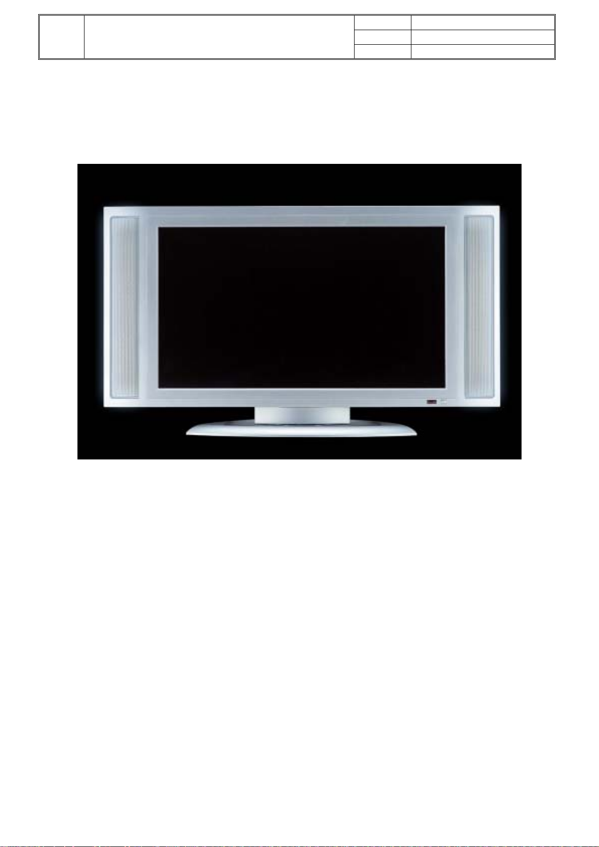
Apex AVL2776 Level 1 Service Manual
AVL2776 LCD TV
DATE 08/19/2004
VER. A1
PAGE 1
Service Manual
Page 2
TITLE
Apex AVL2776 Level 1 Service Manual
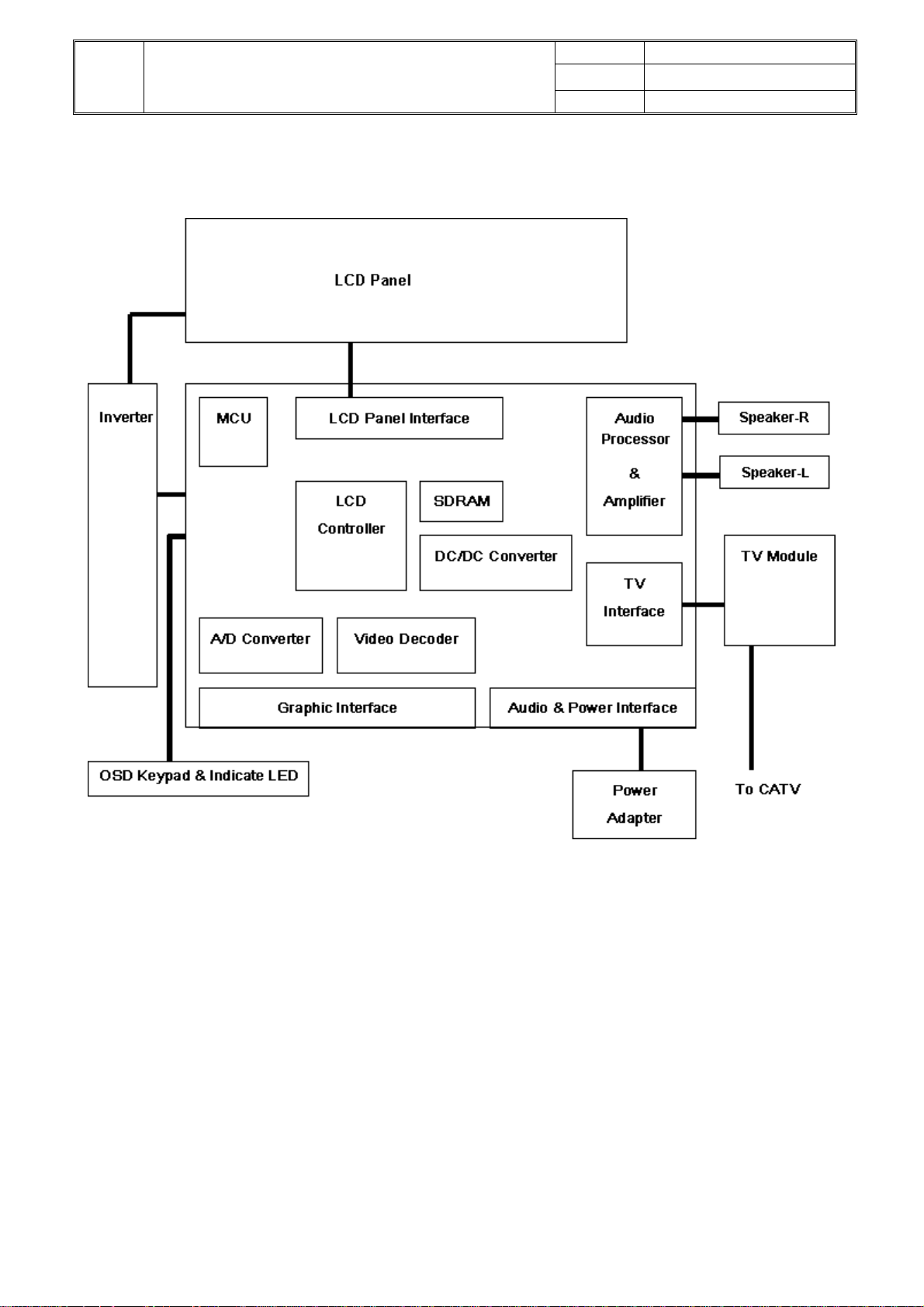
System Block Diagram
DATE 08/19/2004
VER. A1
PAGE 2
2
Page 3
Page 4
Page 5
DATE 08/19/2004
TITLE
Apex AVL2776 Level 1 Service Manual
VER. A1
PAGE 5
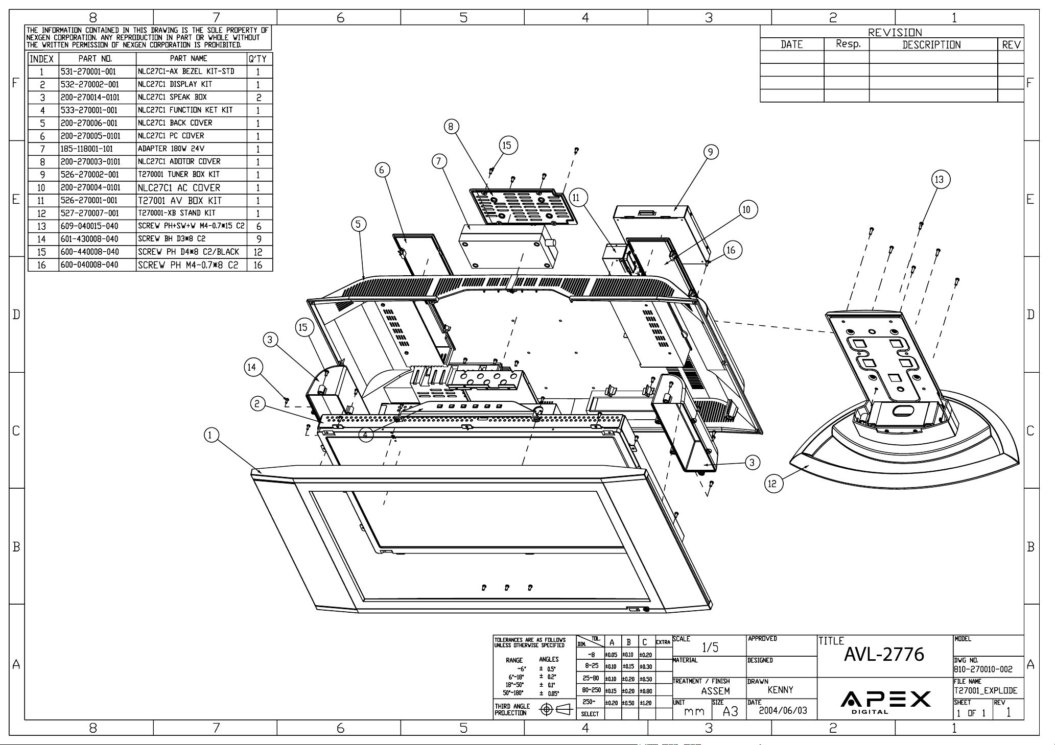
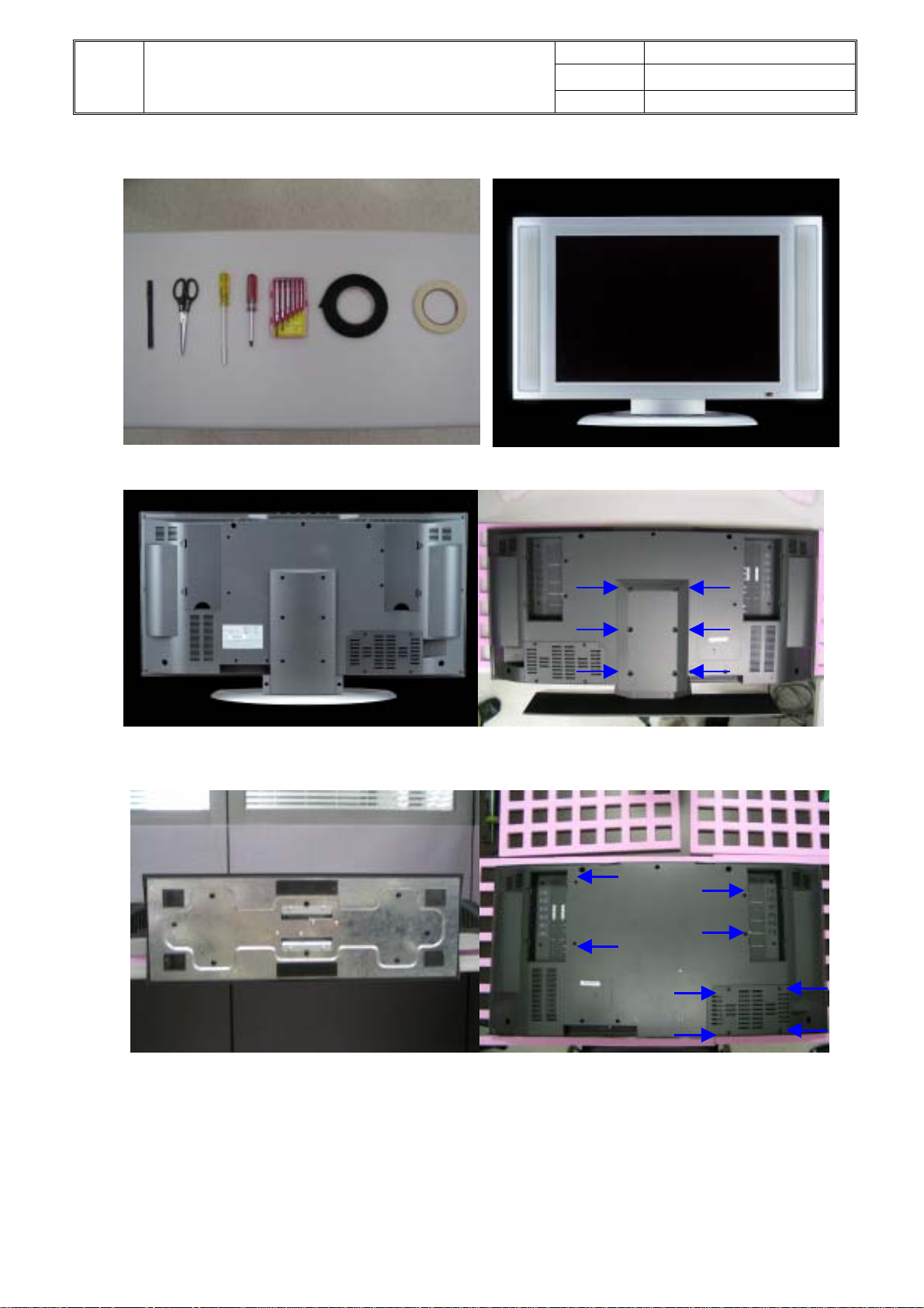
Assembly/Disassembly procedure
Tools AVL2776
Back view Release 6 screws as arrow
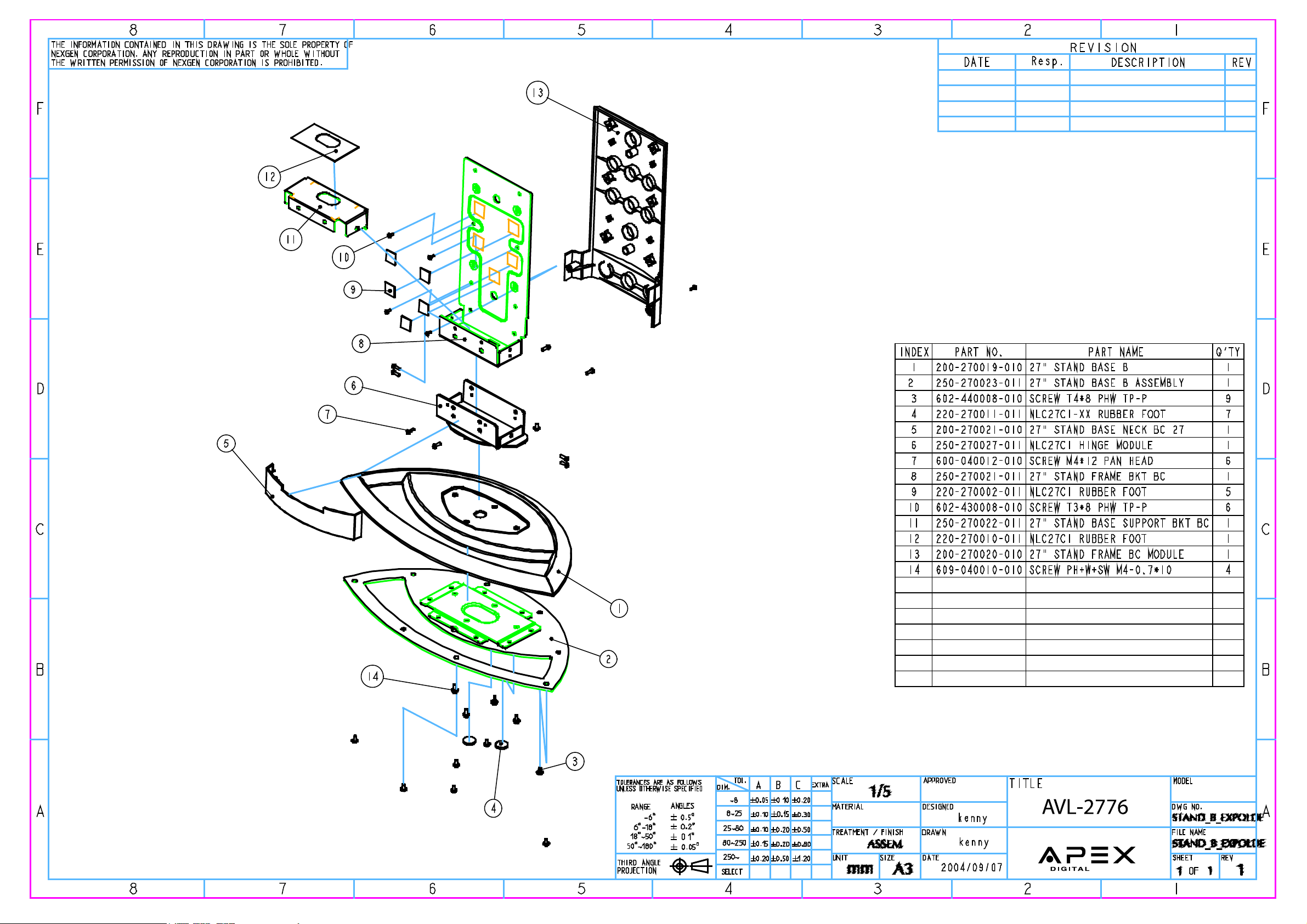
Appearance of stand Release 8 screws as arrows
5
Page 6
TITLE
Apex AVL2776 Level 1 Service Manual
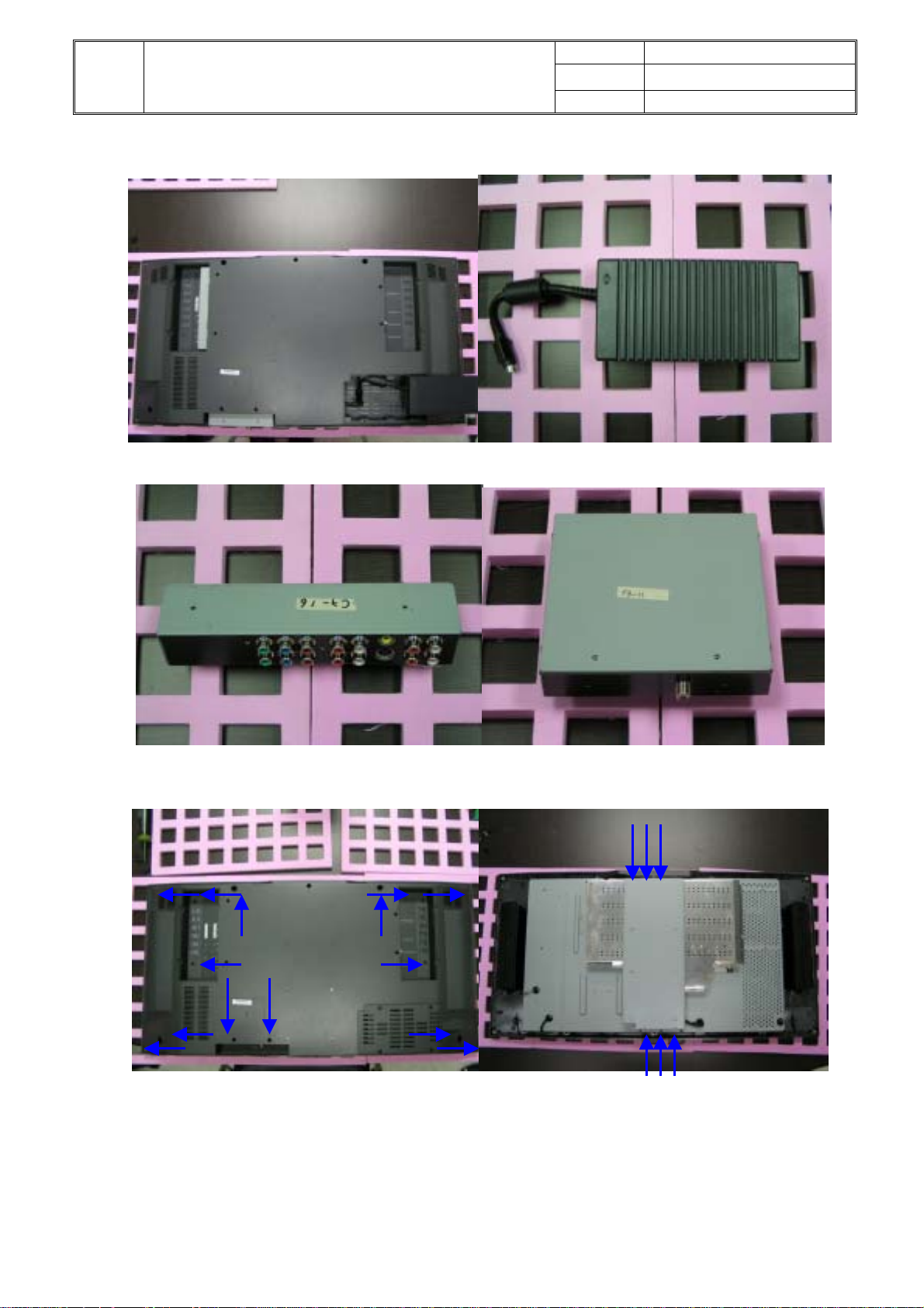
Take of tuner box and AV box Take off adaptor
AV box Tuner Box
DATE 08/19/2004
VER. A1
PAGE 6
Release 15 screws as arrows Take off wall mount bracket
6
Page 7
DATE 08/19/2004
TITLE
Apex AVL2776 Level 1 Service Manual
VER. A1
PAGE 7
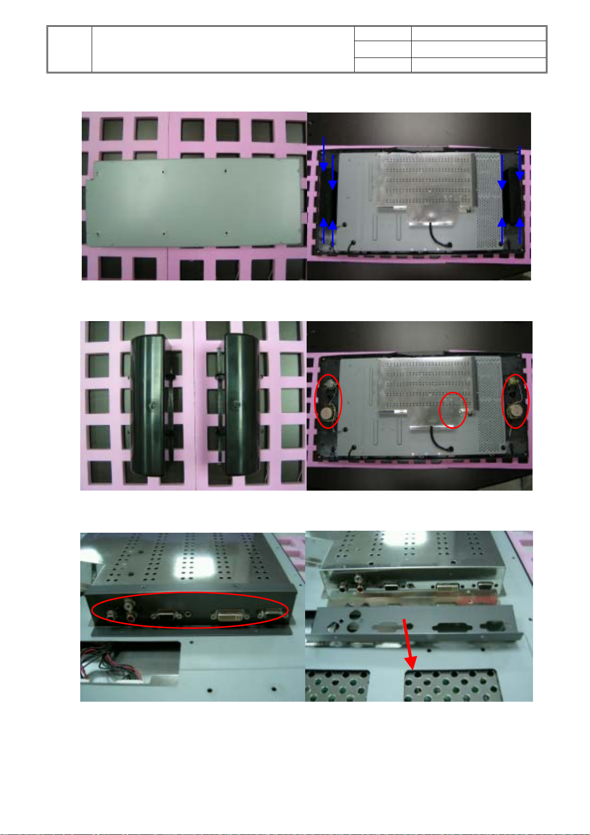
Wall mount bracket Loosen 8 screws on the speaker boxes
SPK boxes Loosen 3 screws and unplug SPK cables
Take off 8 screws and the pc panel bracket Take off PC panel bracket
7
Page 8

DATE 08/19/2004
TITLE
Apex AVL2776 Level 1 Service Manual
VER. A1
PAGE 8
Take off main cover bracket Loosen 8 screws on main board
Disconnect 8 cables and take off Loosen 2 screws on key pad
main board and disconnect two cable of inverter
Take off Key pad set Release 2 screws on key pad
8
Page 9

DATE 08/19/2004
TITLE
Apex AVL2776 Level 1 Service Manual
VER. A1
PAGE 9
Key pad board. Loosen 2 screws on IR board
Loosen 10 screws and separate front
9
Page 10

g
t
N
A
DATE 08/19/2004
TITLE
Apex AVL2776 Level 1 Service Manual
VER. A1
PAGE 10
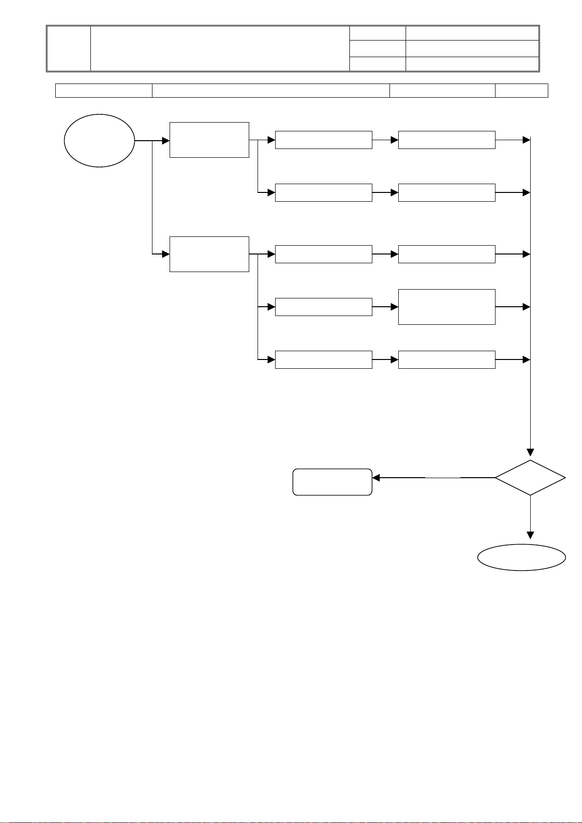
Troubleshooting Analysis
Defect Mode Failure Analysis Repair Testing
Light On Test
Missing Line Check PCB M/B Change
Abnormal
Display
Bright Dot
Dark Dot
Check Panel Panel Change
Backlight
Light Leakage
Mura Check Panel Panel Change
Image Stickin
Brightness spo
Particle
Dot Defect
No display
Check PCB M/B Change
Inverter Change
Check Panel Panel Change
Check PCB M/B Change
Check Panel Panel Change
Next Step
G
TEST
Complete
10
Page 11

A
DATE 08/19/2004
TITLE
Apex AVL2776 Level 1 Service Manual
VER. A1
PAGE 11
Defect Mode Failure Analysis Repair Testing
Flicker Check PCB M/B Change
Image is
too dark
Inverter Change
Gray value
display
Check PCB M/B Change
Check Panel
Panel Change
R. G. B
display
abnormal
Check PCB M/B Change
Check Panel Cable Panel Cable Change
Display
Shut Down
Check PCB M/B Change
Inverter Change
Check Panel Panel Change
VGA No
Image
CheckPCB M/B Change
Check D-sub Cable D-sub Cable Change
Power on
Display
abnormal
Check PCB M/B Change
Next Step
TEST
Complete
11
Page 12

N
DATE 08/19/2004
TITLE
Apex AVL2776 Level 1 Service Manual
VER. A1
PAGE 12
Defect Mode Failure Analysis Repair Testing
ON/OFF
Abnormal
o Power Check PCB M/B Change
Keypad/B Change
Check FFC FFC Change
LED
M/B Change
display
abnormal
LED off
LED Dark Keypad/B Change
Check PCB
LED Abnormal
LED Flicker
Check FFC FFC Change
Power Saving Mode
in VGA
Push Any Key
to Restart
Abnormal
Keyboard
Unavailable Check PCB
M/B Change
Keypad/B Change
Check FFC
FFC Change
Next Step
Completed
TEST
12
Page 13
DATE 08/19/2004
TITLE
Apex AVL2776 Level 1 Service Manual
VER. A1
PAGE 13
Defect Mode Failure Analysis Repair Testing
Other
Abnormal
Display
Display flicker
(tapping )
Check PCB M/B Change
Check Panel Inverter Change
Cannot use
remote control
Check keypad board Keypad Change
Check remote
Remote Control or
Battery Change
Check FFC FFC Change
Next Step
Completed
TEST
13
Page 14

N
r
DATE 08/19/2004
TITLE
Apex AVL2776 Level 1 Service Manual
VER. A1
PAGE 14
Defect Mode Failure Analysis Repair Testing
Audio
Abnormal
Sound adjust
abnormal
Check PCB M/B Change
o sound Check Speake
Speaker Change
Check FFC FFC Change
Single sound Check PCB M/B Change
Keypad/B Change
Hear phone
defect
Check hear phone
Jack
M/B Change
Check FFC FFC Change
Check PCB
M/B Change
TEST
Completed
14
Page 15

N
DATE 08/19/2004
TITLE
Apex AVL2776 Level 1 Service Manual
VER. A1
PAGE 15
Defect Mode Failure Analysis Repair Testing
Video
Abnormal
( AV , SV ,
CV , TV )
AV , SV , CV
o Image
Check PCB M/B Change
Check Cable Cable Change
TV No Image
Check PCB M/B Change
Check RF Cable RF Cable Change
TV No Sound
Check TV Module TV Module Change
Check PCB M/B Change
Check TV Module TV Module Change
TV No Close
Caption
o
r V-Chip
(NTSC)
TV No
Teletext
( PAL ,
SECAM )
Completed
TEST
15
Page 16

DATE 08/19/2004
TITLE
Apex AVL2776 Level 1 Service Manual
VER. A1
PAGE 16
Defect Mode Failure Analysis Repair Testing
Abnormal
BIOS
Upgrade
Can’t Upgrade
BIOS
Check PCB M/B Change
TEST
Completed
16
Page 17

DATE 08/19/2004
TITLE
Apex AVL2776 Level 1 Service Manual
VER. A1
PAGE 17
Use designed ISP tool to upgrade system BIOS:
1.Use RS-232 to link computer RS232 port (If no RS232 port can use USB transform)
and LC2700W RS232 port, as below picture.
2. The CPU used for processing ISP need to burn LD0415.BIN to the LDROM of CPU.
(Have burned before shipping)
3. Need to enter factory mode by press ( + + ) buttons
MENU
VOL+
VOL-
on OSD to execute ISP mode.
1.Push Menu 2.Push “►” button to access Factory Mode
17
Page 18

TITLE
Apex AVL2776 Level 1 Service Manual
3. Press”▼” button to “ISP” item. 4. When press “Vol+” TV will be locked.
4. Execute ispwriter.exe file
To execute CPU ispwriter.exe
DATE 08/19/2004
VER. A1
PAGE 18
file on your PC, and the below screen appears:
5. Move the cursor to click “Select Chip” button and select the type of CPU (W78E65).
W78E65
18
Page 19

DATE 08/19/2004
TITLE
Apex AVL2776 Level 1 Service Manual
VER. A1
PAGE 19
6.Move the cursor to click “5Program Start at APROM” to cancel the selection.
W78E65
7. Move the cursor to click “Select Bank0” button to select the wanted program. The file
format is binary format instead of hex format.
W78E65
8. Select the Port Name on Communication Setting screen.
19
Page 20

DATE 08/19/2004
TITLE
Apex AVL2776 Level 1 Service Manual
VER. A1
PAGE 20
9. Move the cursor to click “Connect” button to link. If the linking succeeds, below screen
will appear.
W78E65
10. Click “Program All” button to auto-execute erase and program function. After
execution below screen will appear. Click “confirm” button to finish the execution.
11. To click “verify” button to execute verify function. After verification, below screen will
appear. Click “confirm” button to finish the verify function.
20
Page 21

DATE 08/19/2004
TITLE
Apex AVL2776 Level 1 Service Manual
VER. A1
PAGE 21
12. After updating APROM program, disconnect ISP tool. Power on LCD TV again.
21
 Loading...