

Page 1
MEC-MULTIMEC5E-2008
Multimec™ 5E
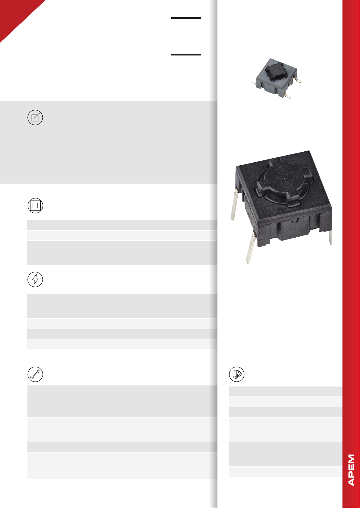
High performance tactile switches •
MIL-PRF-28855H
DISTINCTIVE FEATURES
Momentary switches with NO or NC/NO function
Sealed to IP67
Robust
Anti-rotation thanks to snap-on cap retetion system
3 standard actuation forces: 2.0, 3.5 and 6.5 N
ENVIRONMENTAL SPECIFICATIONS
• Sealing : IP67 according to IEC 60529
• Working and storage temperature : -40 °C/+160 °C (-40 °F to +320 °F)
• Soldering :
- through-hole : IEC 60068-2-20 8
- surface mount : JEDEC J-STD-020E
PCB SWITCHES
PANEL SWITCHES
ELECTRICAL SPECIFICATIONS
• Recommended load :
- Gold contacts : 0.5µ-50 mA 24 VDC
- Silver contacts : 0.5-50 mA 24 VDC
• Contact resistance : <30 mΩ - typically 10 mΩ
• Insulation resistance : >10 MΩ
• Contact bounce : <2 mS - typically 0.5 mS
MECHANICAL SPECIFICATIONS
• Standard actuation force :
- momentary NO : 2.0 N, 3.5 N, 6.5 N
- quiet version : 2.0 N
- NC/NO function : 3.5 N
• Max. actuation force :
- momentary : 115 N for 60 sec (according to MIL-PRF-22885H)
- NC/NO : 100 N for 10 sec
• Travel : 1 mm
• Lifetime :
- NO : >10,000,000 cycles
- NC/NO : >1,000,000 cycles
The company reserves the right to change specifications without notice. All tolerance if not otherwise specified ±0.2 mm.
MATERIALS
• Housing : PPS UL94V0
• Actuator : PPS UL94V0
• Sealing : Silicone rubber
• Contacts spring : Stainless steel
Silver : +3 µAg
Gold : +1 µAu
• Fixed contacts :
Silver : SnCu + 2 µNI + 3 µAg
Gold : SnCu + 2 µNI + 1 µAu
• Terminals : SnCu + 2 µNI + 3 µSn100
1
Page 2
Multimec™ 5E
10
10
14
0,3
6,4
0,3
10,16Min
Max 12,5
0,3
4
6,4
6,5
13,9
7,62124,8
10,16
7
,
6
2
Ø 0,9
1
3
2
4
High performance tactile switches •
MIL-PRF-28855H
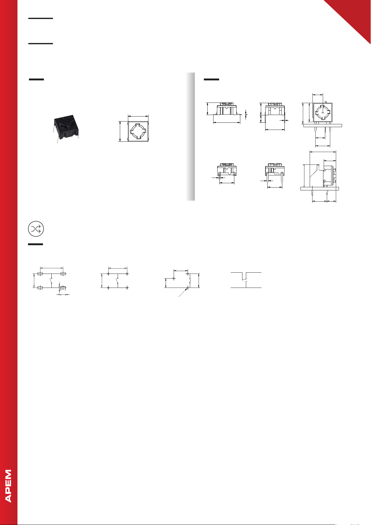
PCB SWITCHES
5E
• SMD, TH or right angle TH
• NO or NC/NO
All tolerances unless otherwise noted : ± 0.2 mm
PCB LAYOUT & CIRCUIT DIAGRAM
SMD
12,50
2
2
6
,
7
4
1
,2
3
1
2,5
TH
10,16
2
2
6
,
7
4
1
3
Ø 0,9
5,08
Ø1,0(3x)
RAS
7,62
SMD RASTH
6,4
14
0,8
7,62
0,3
6,4
4
0,8
10,16Min
Max 12,5
7,62
5,5
0
11
□1
5,08
7,62
13,9
6,5
7,62124,8
NC/NO function
*not for sale in Japan
1
7,62
3
2
4
1
3
2
Page 3
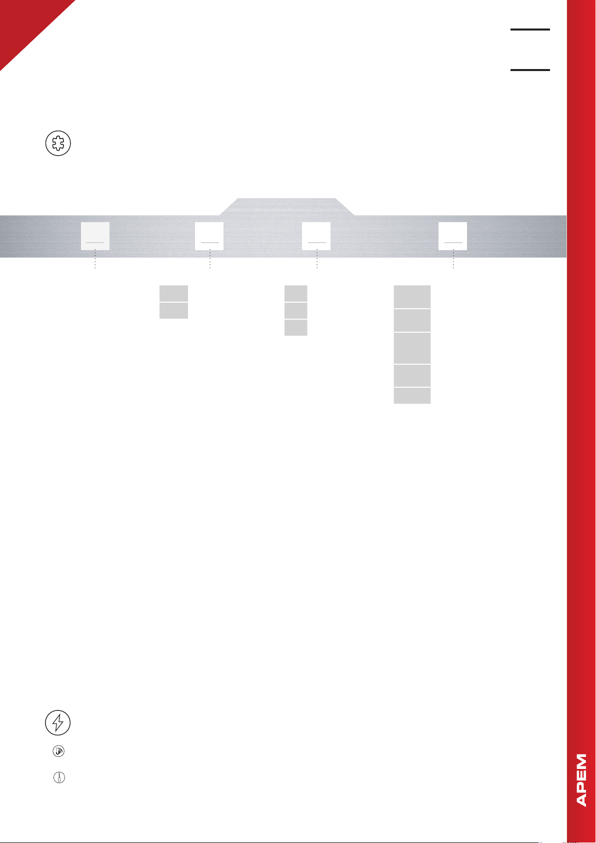
BUILD YOUR PART NUMBER
5E
Multimec™ 5E
High performance tactile switches •
MIL-PRF-28855H
PCB SWITCHES
PANEL SWITCHES
NON-ILLUMINATED
SERIES
TH9
SH9
MOUNTING
Through-hole
Surface mount
ACTUATION FORCE
2.0 N
20
3.5 N
35
6.5 N
65
Q
RAS
NCNO
R
G
OPTIONAL
Quiet contact
(with 2.0 N only)
Right angle
(with TH only)
Normally closed/
normally open function
(with 3.5 N only)
Tape & reel
(with SMD only)
Gold contacts
ABOUT THIS SERIES
Laser marking on the switch for identification : WWYS, WW=week, Y=year, S=suffix for the type of switch, e.g. P=2.0 N and silver
contacts, S=3.5 N and silver contacts, E6.5 N and silver contacts
Caps : see www.apem.com for more information.
3
Page 4
Multimec™ 5E
10
L(mm)
10
L(mm)
High performance tactile switches •
MIL-PRF-28855H
PCB SWITCHES
TAPE & REEL
Tape and reel is available for the parts listed and has the
following specifications
• Reel diameter: Ø330 mm
• Tape width: 24 mm
• Pitch: see list
• Tape and reel material: antistatic or better
• Quantity per reel: see list
PART NO. ORDERING CODE PITCH
QUANTITY
PER REEL
5ESH9XX 5ESH9XXR 16 500
5ESH9XX1SSXX-08.0 5ESH9XXR1SSXX-08.0 20 250
5ESH9XX1SSXX-09.5 5ESH9XXR1SSXX-09.5 20 250
5ESH9XX1SSXX-10.4 5ESH9XXR1SSXX-10.4 20 250
5ESH9XX1SSXX-11.0 5ESH9XXR1SSXX-11.0 20 250
5ESH9XX1SSXX-12.0 5ESH9XXR1SSXX-12.0 20 250
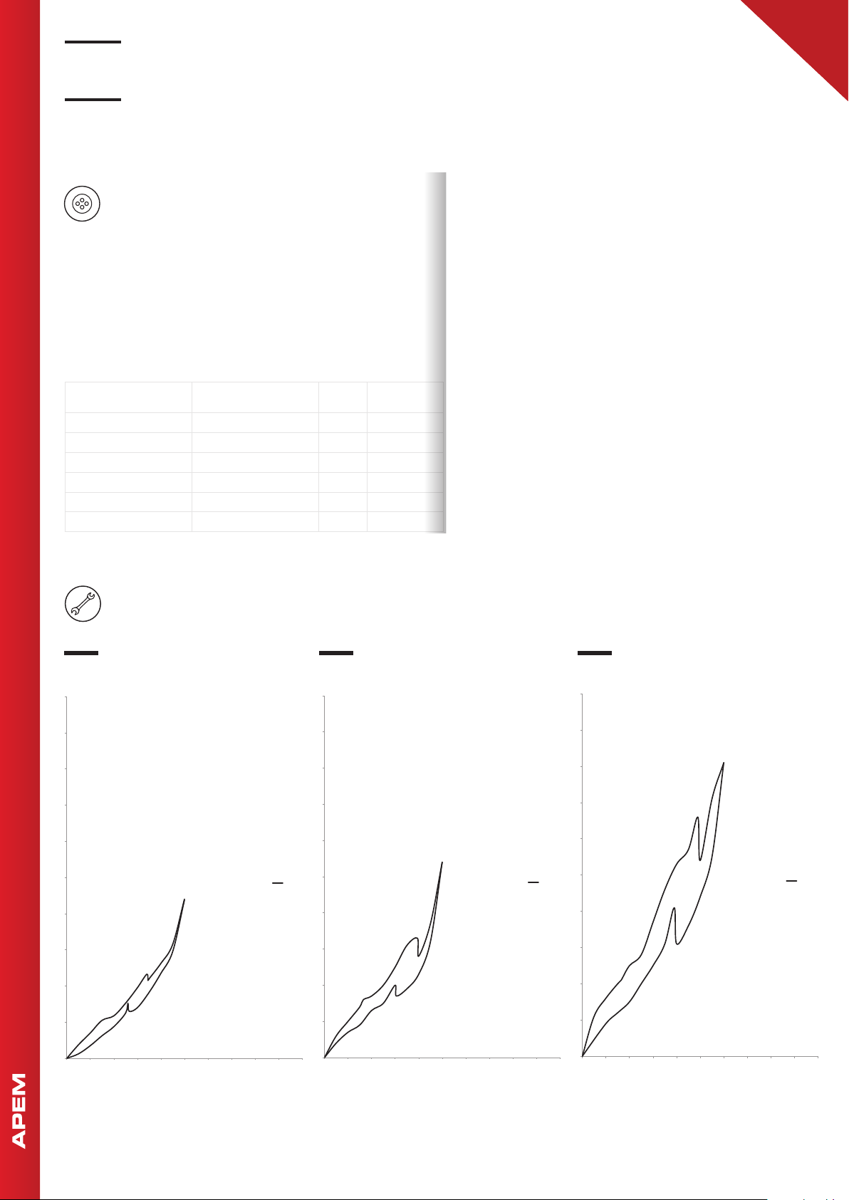
OPERATING FORCE
TRAVEL
10
9
8
7
6
3.5 N
FORCE
2.0 N
FORCE
9
8
7
6
6.5 N
FORCE
9
8
7
6
5
F(N)
4
3
2
1
0
0 0,2 0,4 0,6 0,8 1 1,2 1,4 1,6 1,8 2
TRAVEL
4
5
F(N)
2N
4
3
2
1
0
0 0,2 0,4 0,6 0,8 1 1,2 1,4 1,6 1,8 2
L(mm)
3,5N
TRAVEL
5
F(N)
4
3
2
1
0
0 0,2 0,4 0,6 0,8 1 1,2 1,4 1,6 1,8 2
TRAVEL
6,5N
Page 5
High performance tactile switches •
15,24Min.
10,3
M
in.
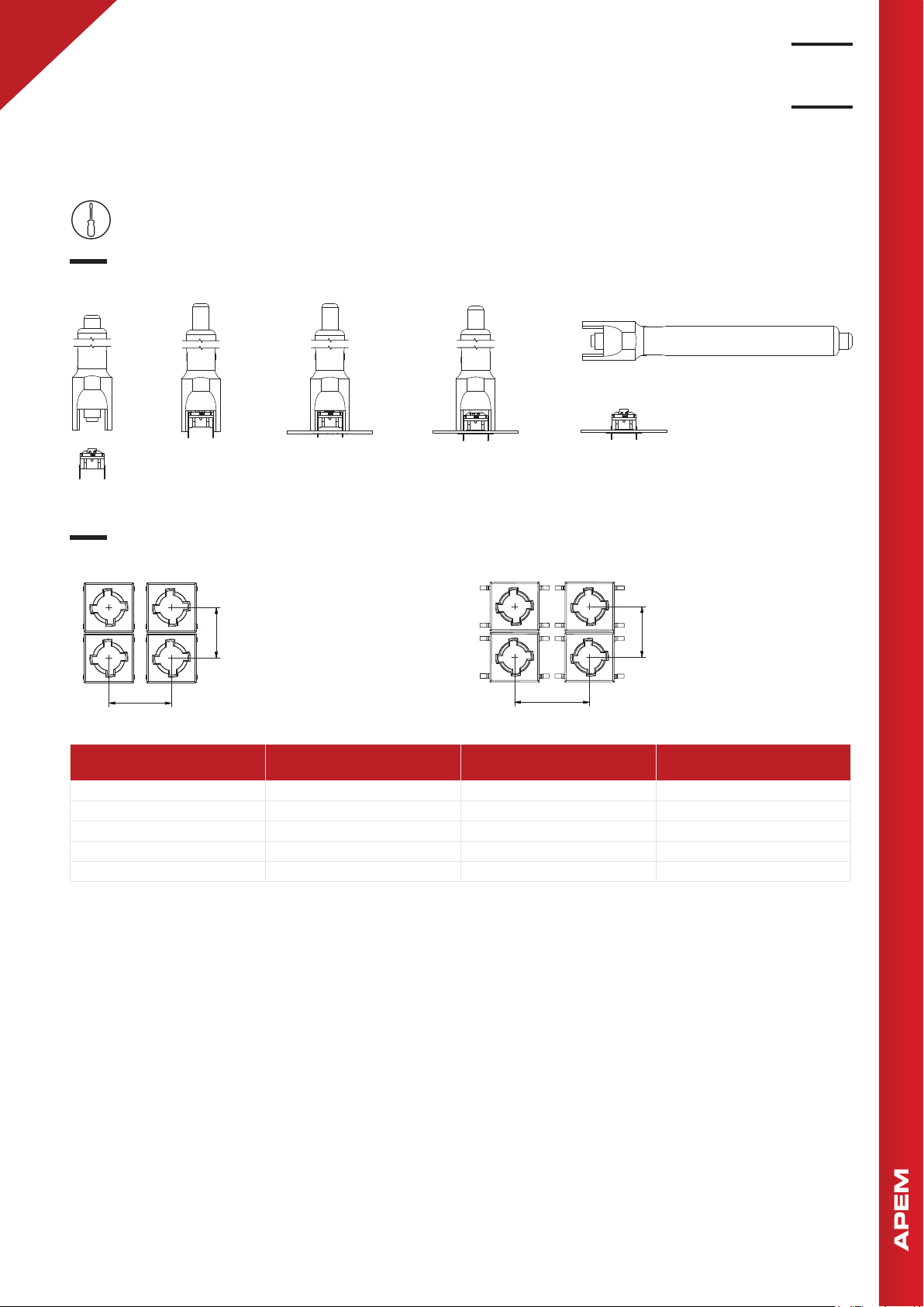
MOUNTING
MOUNTING TOOLS FOR MULTIMEC™ THROUGH-HOLE SWITCHES
1 2 3 4 5
Multimec™ 5E
MIL-PRF-28855H
PCB SWITCHES
PANEL SWITCHES
Part No. 9861000
SPACE REQUIREMENT - MATRIX MOUNTING
10,3
in.
M
12,7Min.
CAP SERIES
1PS 12.7x10.3 6.5x12.5 7.0x13.0, R max. 1.0
1SS 12.7x10.3 Ø6.5 Ø7.0
1YS/1YAS 15.3x15.3 15.0x15.0 16.0x16.0
1Z/1ZW 35.5x35.5; 41.6x41.6 Ø29.5 Ø30.3
10A+10AWY 22.0x40.0 R=5.3; 10.6x28.0 R=5.5; 11.0x28.4
10,3
in.
Through-hole (TH) Surface mount (SMD)
15,24Min.
RECOMMENDED
MIN.SWITCH SPACING AxB
NOMINAL CAP DIMENSION
WxH
M
RECOMMENDED
MIN. PANEL CUT-CUT
5
Page 6
Multimec™ 5E
High performance tactile switches •
MIL-PRF-28855H
PCB SWITCHES
USAGE GUIDELINES
HOW TO GET THE BEST RESULTS WITH
MEC SWITCHES ?
These guidelines are offered to users of MEC Switches as
an aid to ensure successful and reliable switch operation.
Please see the technical specifications for details on operating and storage temperatures and soldering guidelines
to make sure you select the best switch for your application. When reflow soldering is taking place, MEC strongly
recommend that the temperature profile is analyzed and
compared with the temperature rating of the switch. It is
also important to monitor the accumulated heat buildup
from both the pre-heat zones and the solder zone.
Most standard accessories for multimec™ 5 series switches
are made from ABS plastic with a maximum operating
temperature of 65 °C. It is strongly recommended that
accessories are mounted after soldering of the switch. If
this is not possible care must be taken not to overheat the
accessories during the soldering process. The 1SS caps
are, however, made of high temperature materials and will
meet the same temperature specifications as the switches.
For accessories made from other plastic materials please
see multimec™ 5 series cap & bezel specifications.
MOUNTING AND DISMOUNTING
If switches are to be mounted in rows it is essential that
the recommendations regarding spacing are followed. PC
board thickness should be 1.4 ±0.2 mm and terminal hole
diameter should be 0.9 mm.
All multimec™ 5 series caps are easily snapped onto the
switch modules and can be changed at a later time.
SOLDERING - THROUGH HOLE
VERSIONS
Hand soldering: max. 350 °C for max. 3 sec
Wave soldering: heat built up in the switch during
pre-heating and soldering must not exceed the
maximum operating temperature of the switch. Peak
temperature must not exceed 260 °C, and soldering
time is max 10 sec. (IEC 600-68-2-20 8)
SOLDERING - SURFACE MOUNT
VERSIONS
For all methods - infrared, convection and vapor
phase. The upper limit 240 °C/40 sec must be observed. The soldering temperature profile must have
moderate temperature gradients. (JEDEC J-STD020E)
ROHS COMPLIANCE
As of 1 July 2006 MEC has completed the conversion
to RoHS compliance. For more info please see our
homepage www.apem.com
TEMPERATURE LIMITS:
Switch 160 °C
Accessories 65/85/160 °C
A mounting tool is available for through hole multimec™ 5
series switches.
SOLDERING AND CLEANING
MULTIMEC™ SERIES
Multimec™ 5 series switches are fully sealed to IP67 specifications to minimize solder flux and aqueous based cleaning solutions from entering the switch and contaminating
the contacts. The switches can be placed on the PC board
with other components and reflow soldered. Multimec™ 5
series offers a high level of sealing, however, with aqueous
solvent solutions care must be taken to avoid the worst
case situation with water jets, complete immersion into a
liquid with a temperature below the board or surface tension reducing additives.
Recommended cleaning methods are demineralized
water. Any surface tension reducing agents, such as soap,
must not be used as they risk causing a potential leakage
of the switch.
6
PACKAGING
Multimec™ 5 series switches are packed in rigid
tubes of 50 pieces each.
A box contains 1.000 pcs.
The surface mount versions of multimec™ 5E series
switches with a height up to 12.5 mm can also be
delivered on tape/reel.
Each reel contains 250/500 pcs.
Right angle switches are packed into trays.
Each tray contains 100 pcs.
 Loading...