

Page 1
6,5
10,16Min
0,3
0,8
7,62
6,5
0,3
14
6,4
7,62
12,0 - 22,5
10,4 - 22,5
1SS
1LS
1IS
6,5
14
0,3
7,62
6,5
10,16Min
Max 12,5
0,3
0,8
7,62
3
10,3Max
6,5
0,3
14
6,4
10,3Max
0,8
7,62
12,0 - 22,5
10,4 - 22,5
1SS
1LS
1IS
8,0 - 22,5
6,5
0,3
14
6,4
7,62
10,4 - 22,5
1LS
1IS
6,5
10,16Min
Max 12,5
0,3
0,8
7,62
6,5
0,3
14
6,4
10,3Max
0,8
7,62
12,0 - 22,5
10,4 - 22,5
1LS
1IS
1IS
6,5
0,3
14
6,4
7,62
10,4 - 22,5
1IS
multimec®
7,62
0,8
6,5
10,16Min
Max 12,5
0,3
0,8
7,62
3
10,3Max
6,5
0,3
14
6,4
10,3Max
0,8
7,62
12,0 - 22,5
10,4 - 22,5
1SS
1LS
1IS
8,0 - 22,5
10,16Min
0,8
7,62
3
10,3Max
6,5
0,3
14
6,4
10,3Max
0,8
7,62
12,0 - 22,5
10,4 - 22,5
1LS
1IS
6,4
0,8
7,62
10,4 - 22,5
1IS
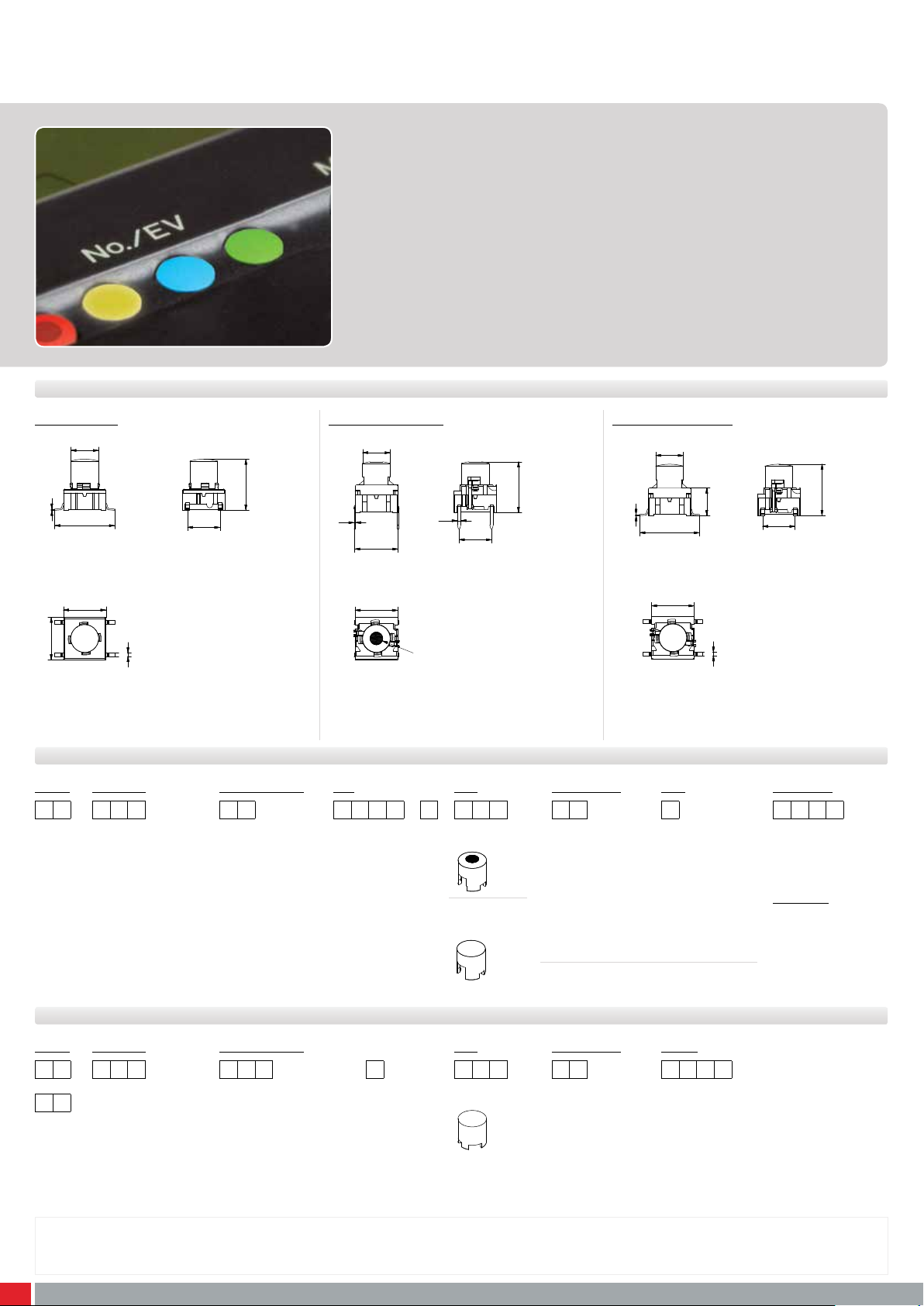
Cap range with variable heights and illumination options
■ Round caps
■ 9 standard options in overall height
■ Ø6.5 mm
■ h =8-22.5 mm; 10.4-22.5 mm; 12-22.5 mm
■ Material: polyamide
■ Temp. Range:
• Solid cap: -40/+160°C (1SS); -40/+65°C (1LS)
• Transparent cap: -40/+85°C
■ Panel cut-out: 1SS/1LS/1IS-Ø7.0
All dimensions in mm Tolerances -/+0.2mm
DIMENSIONS
SMD (5E) + 1SS TH w/LED (5G) + 1LS SMD w/LED (5G) + 1IS
5E/5G + 1SS/1IS/1LS
6,5
0,3
14
10
10
0,8
7,62
8,0 - 22,5
6,5
0,3
10,16Min
Max 12,5
10,3Max
0,8
7,62
3
12,0 - 22,5
6,5
0,3
14
10,3Max
ILLUMINATED – HOW TO ORDER
Switch
Mounting
Actuation force
5 G
TH9 through-hole
SH9 surface mount
20
35
65
Q*
*For an illuminated quiet 2.0N switch add Q
to the end of the switch part number.
NON-ILLUMINATED– HOW TO ORDER
Switch
5 E
5 G
Mounting
TH9 through-hole
SH9 surface mount
Actuation force
20
20Q
35
65
Ordering example:
5ETH920+1SS04-09.5 without illumination OR 5GSH93542+1IS16-19.0 with illumination OR *5GTH9208222Q (illuminated quiet version)
Please see colour codes, updates of products and changes of specifications on www.apem.com
16
LED
02 blue
22 green
42 yellow
61 white
82 red
2242 green/yellow
8222 red/green
8242 red/yellow
Cap
Colour code
Lens
+
1LS with lens
1IS fully
illuminated
00 blue
02 green
03 grey
04 yellow
06 white
08 red
1 transparent
2 green
4 yellow
6 frosted white
8 red
09 black
11 transparent
16 frosted white
+
Cap
1SS solid colour
Colour code
00 blue
02 green
03 grey
04 yellow
06 white
08 red
09 black
Height
08.0 16.0
09.5 19.0
10.4 22.5
11. 0
12.0
15.0
6,4
7,62
0,8
10,4 - 22,5
Height 1LS
.
12.0 19.0
15.0 22.5
16.0
Height 1IS
10.4 16.0
11.0 19.0
12.0 22.5
15.0
.
Page 2
multimec®
14
0,3
11,0
7,62
0,8
14
0,3
11,0
7,62
0,8
30,0
22
5,1
5,1
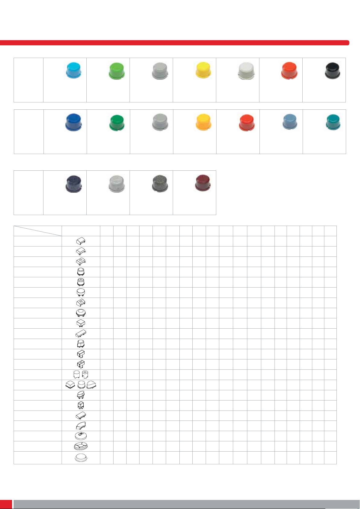
Solid colours
No.
Colour
RAL Code
No.
Colour
RAL Code
00
blue
5012
30
ultra blue
5002
Metallic Colours
No.
Colour
RAL Code
CAP
1A
1B
1C
1DS
1ES/1FS
1GAS/1GCS
1H
1JS
1KS
1M
1NS
1PS
1QS/1RS
1SS/1LS
1TS/1US/1VS
1WAS/1WDS/1WPS
1XS
1ZA
1ZB
1ZCS
1Z/1ZW
10R/10RF + 10Q
50
dark blue
No Ral Code
CODE
02
green
6018
32
mint green
6029
53
light grey
No Ral Code
03
grey
7004
33
tele grey
7046
57
dark grey
No Ral Code
04
yellow
1023
34
melon
1028
58
bordeaux
No Ral Code
06
white
9010
38
noble red
3002
08
red
3000
40
dusty blue
5014
09
black
9004
42
aqua blue
5021
00 02 03 04 06 08 09 30 32 33 34 38 40 42 50 53 57 58
• • • • • • •
• • • • • • •
• • •
• • • • • • • • • • • • • • • • • •
• • • • • • •
• • • • • • •
• •
• • • • • • •
• • • • • • •
• • • • • • •
• •
• • • • • • •
• • •
• • • • • • •
• • • •
• • • • • • • • •
• • • • • • •
• • • • • • • • • •
• • • • • • • • • •
• • • • • • • • • • •
• • • • •
• • • • • • •
The RAL Codes mentioned are the codes nearest to the solid colors in the multimec® range.
For product updates and/or changes of specifications please see www.apem.com
58
Page 3
multimec®
10,16Min
Max 12,5
0,3
4
7,62
0,8
7,62
0,8
6,4
10
10
7,62
0,8
10,16Min
Max 12,5
0,3
4
7,62
0,8
7,62
0,8
10,16Min
Max 12,5
6,4
4
6,4
10
10
8,5
7,62
0,8
10,16Min
Max 12,5
7,62
0,8
7,62
0,8
10,16Min
Max 12,5
0,3
4
7,62
0,8
6,4
10
8
0,8
7,62
R
1
1
,
5
1
1
,7
0,8
7,62
8
1
,8
14
0
,3
7
,6
2
12,50
2,5
1
,2
1
3
2
4
8
0,8
7,62
1
,8
14
1
1
,7
R
1
1
,
5
7,62
0,8
14,3Ø
8
0
,3
12,50
7
,6
2
2,5
1
,2
+3
-2 1
4
12,50
7
,6
2
1
,2
0
2,50
-2 1
4
+3
7,62
0,8
10,16Min
Max 12,5
0,3
4
7,62
0,8
6,4
14
0,3
6,4
7,62
0,8
10,16Min
Max 12,5
0,3
4
7,62
0,8
0,8
6,4
4
6,4
6,4
0,8
7,62
10
1
0
10
10
7,62
0,8
10,16Min
Max 12,5
0,3
4
7,62
0,8
7,62
0,8
10,16Min
6,4
4
6,4
10
10
10,16Min
0,3
4
7,62
0,8
6,4
8,5
7,62
0,8
8,5
0,3
0,8
8,5
0,3
0,8
14
0,3
6,4
7,62
0,8
10,16Min
Max 12,5
0,3
4
7,62
0,8
7,62
0,8
10,16Min
Max 12,5
6,4
4
6,4
14
0,3
6,4
0,8
7,62
10
1
0
10
10
10
10
10
14
0,3
7,62
0,8
8,5
10,16Min
Max 12,5
7,62
0,3
0,8
10,3Max
10,3Max
14
0,3
6,4
7,62
0,8
10,16Min
Max 12,5
0,3
4
7,62
0,8
6,4
10
1
0
10
10
1
1
,7
R
1
1
,
5
7,62
0,8
R
1
1
,
5
1
1
,7
0,8
7,62
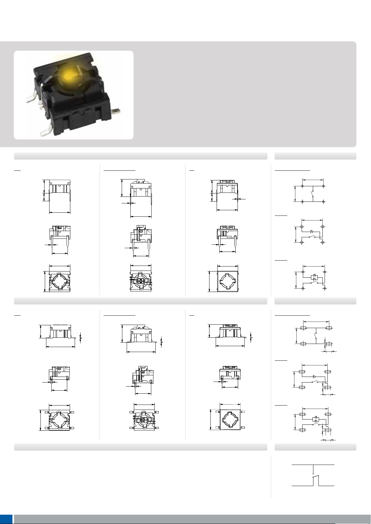
5 series switches basic switch modules
■ rough-hole (TH) or surface mount (SMD)
■ 50mA/24VDC
■ Single pole/momentary
■ 10,000,000 operations lifetime (NO function)
■ Temperature range:
• Switch: -40/+160°C
• LED: -40/+85°C
■ IP 67 sealing
■ Actuation force: 2.0N, 3.5N, 6.5N
■ NO or NC/NO
All dimensions in mm Tolerances -/+0.2mm
THROUGH-HOLE (TH)
5G
6,4
4
10
0,8
10,16Min
Max 12,5
7,62
10
5G illuminated
0,3
0,8
10,16Min
Max 12,5
7,62
10,3Max
5E
10
6,4
4
0,8
10,16Min
Max 12,5
7,62
SURFACE MOUNT (SMD)
5G
■ Available for 5E and non-illuminated 5G in 3.5N actuation force.
■ Same PCB layout as the NO 5E and 5G
■ Housing colour is grey
14
0,8
7,62
10
NORMALLY CLOSED/NORMALLY OPEN FUNCTION NOT FOR SALE IN JAPAN
■ Switch point 0.7 mm +/- 0.3 mm
■ Return point 0.5 mm +/- 0.3 mm
38
Please see colour codes, updates of products and changes of specifications on www.apem.com
0,3
5G illuminated
0,8
0,3
14
7,62
5E
6,4
14
0,8
7,62
0,3
PCB L AYOUT
Non-illuminated
10,16
1 LED
2
2
,6
7
4
2
2
,6
7
4
10,16
Ø 0,9
1
3
Ø 0,9
1
3
2 LED
10,16
-2 1
2
,6
7
4
Ø 0,9
+3
PCB L AYOUT
Non-illuminated
0,3
12,50
2
2
,6
7
4
1
,2
3
1
2,5
1 LED
12,50
-2 1
2
,6
2 LED
7
4
-2 1
2
,6
7
4
12,50
,2
1
+3
2,5
0
,2
1
+3
2,50
CIRCUIT DIAGRAM
3
1
4
2
Page 4
multimec®
6,5
13,9
5,5
7,62124,8
12
13,8
7,62
1
7,62
4,85
5,5
8,0 to 22,57,4
12
7,62
4,85
22,3
12
13,8
7,62
4,85
13,9
6,5
13,9
7,62
7,62
5,08
1
3
5,5
7,62
5,08
7,62
12
4,8
12
5,08
12
13,8
7,62
1
3
7,62
7,62
5,08
Ø1,0(3x)
4,85
7,62
5,5
13,8
5,08
12
13,8
7,62
1
3
7,62
7,62
5,08
Ø1,0(3x)
4,85
7,62
5,5
8,0 to 22,57,4
4:1 5G RAS + 1SS
5,08
12
7,62
7,62
7,62
5,08
Ø1,0(3x)
4,85
7,62
22,3
5,5
1
3
6,5
13,9
7,62
12
4,8
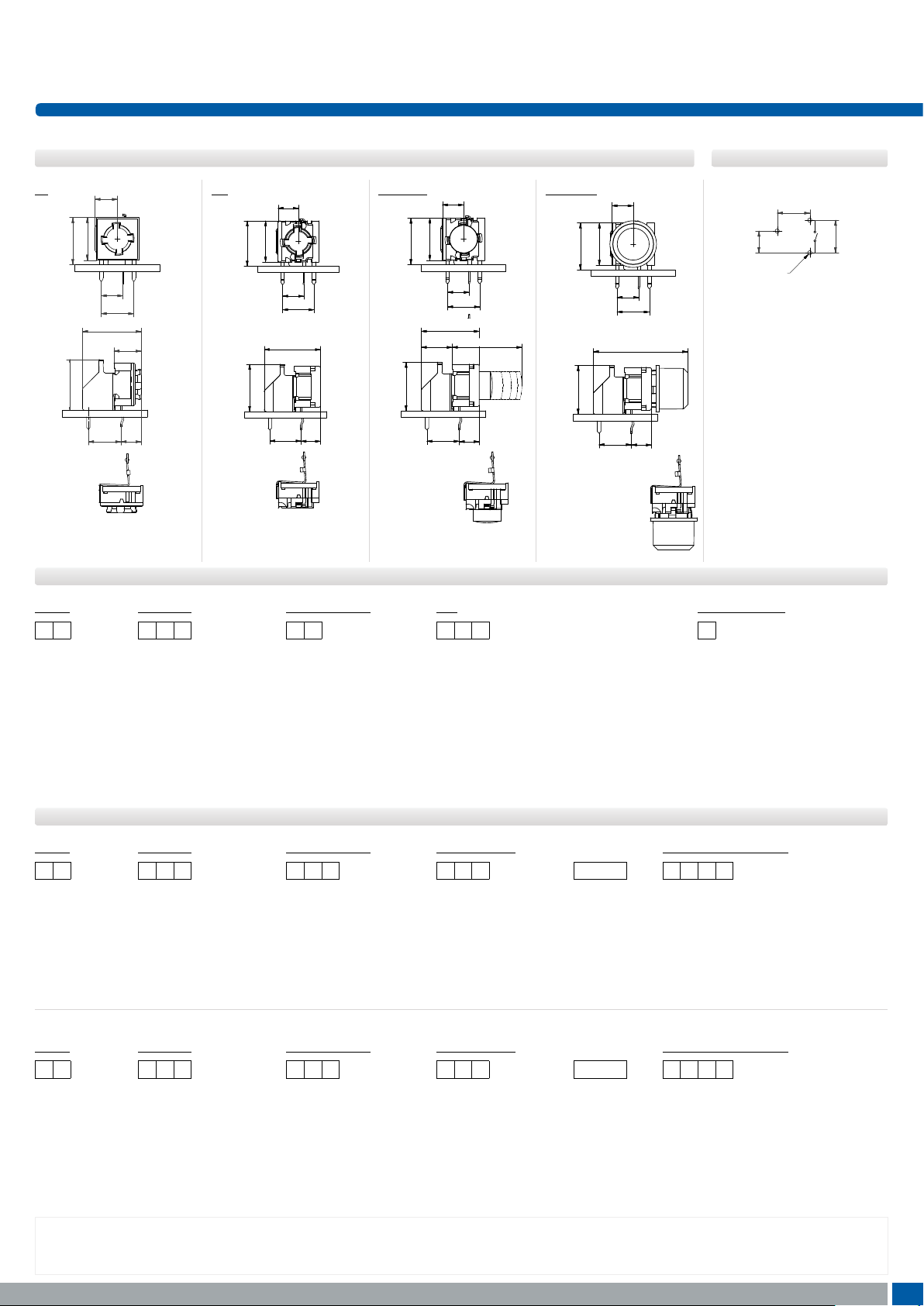
5 series switches basic switch modules
RIGHT ANGLE SWITCHES PCB L AYOUT
5E 5G 5G + 1SS
5,5
11
10
7,62124,8
5,08
7,62
6,5
11
10
5,08
7,62
13,8
7,62
4,85
11
12
ILLUMINATED – HOW TO ORDER
Switch
Mounting
Actuation force
5 G
10
7,62
LED
5,08
7,62
4,85
5G + 1DS
5,5
11
10
5,08
7,62
8,0 to 22,57,4
12
7,62
22,3
4,85
5,08
Ø1,0(3x)
7,62
1
7,62
3
multimec® 5 series has
only normally open (NO)
non-illuminated right angle
switch.
Quiet (optional)
TH9 through-hole
SH9 surface mount
20
35
65
02 blue
22 green
42 yellow
61 white
82 red
2242 green/yellow
8222 red/green
8242 red/yellow
Q
only for 2.0N
NON-ILLUMINATED– HOW TO ORDER
Switch
5 E
Mounting
TH9 through-hole
SH9 surface mount
Actuation force
20
20Q
RAS (optional)
RAS right angle switch
NC/NO (only for 3.5N)
or
NCNO normally closed/
normally open function
35
65
Switch
5 G
Ordering example: 5ESH935 (non-illuminated), 5GTH9658222 (illuminated), 5GSH935NCNO (normally closed/normally open); 5ETH920RAS (right angle)
5ETH920Q or 5GSH92061Q (quiet versions)
Please see colour codes, updates of products and changes of specifications on www.apem.com
Mounting
TH9 through-hole
SH9 surface mount
Actuation force
20
20Q
RAS (optional)
RAS right angle switch
NC/NO (only for 3.5N)
or
NCNO normally closed/
normally open function
35
65
39
Page 5
multimec®
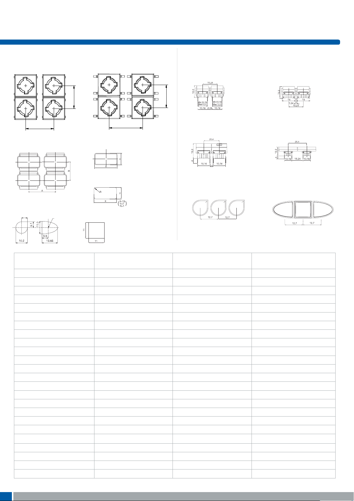
Spacing examples
multimec
®
3AT + 1B/C + 2A/B
multimec
®
3AS + 1B +2A/B
4AS +1B/1C + 2C/2D
multimec
®
3AS + 1B +2A/B
4AS +1B/1C + 2C/2D
multimec
®
3AS + 1B +2A/B
4AS +1B/1C + 2C/2D
multimec
®
3AT + 1M
Spacing examples
multimec
®
3AT + 1B/C + 2A/B
multimec
®
3AS + 1B +2A/B
4AS +1B/1C + 2C/2D
multimec
®
3AT + 1A/H
multimec
®
3AT + 1M
through-hole surface-mount
Switch spacing Cap dimension
Panel cut-out
Spacing examples
multimec
®
3AT + 1B/C + 2A/B
multimec
®
3AS + 1B +2A/B
4AS +1B/1C + 2C/2D
multimec
®
3AT + 1A/H
multimec
®
3AT + 1M
multimec
®
1N + 1N + 1N
®
spacing
Spacing examples
multimec
®
3AT + 1B/C + 2A/B
multimec
®
3AS + 1B +2A/B
4AS +1B/1C + 2C/2D
multimec
®
3AT + 1A/H
multimec
®
3AT + 1M
multimec
®
®
spacing
Panel cut-out
Spacing examples
multimec
®
3AT + 1B/C + 2A/B
multimec
®
3AS + 1B +2A/B
4AS +1B/1C + 2C/2D
multimec
®
3AT + 1A/H
multimec
®
3AT + 1M
multimec
®
1N + 1N + 1N
®
spacing
®
multimec
®
3AS + 1B +2A/B
4AS +1B/1C + 2C/2D
®
multimec
®
3AT + 1M
®
®
multimec
®
3AS + 1B +2A/B
4AS +1B/1C + 2C/2D
®
multimec
®
3AT + 1M
®
®
Basic switch spacing
through-hole surface-mount
Recommended switch/cap spacing
Switch spacing Cap dimension
Panel cut-out
Panel Cut-out
1N 1V 1T
Spacing examples
multimec
®
3AT + 1B/C + 2A/B
multimec
®
3AS + 1B +2A/B
4AS +1B/1C + 2C/2D
multimec
®
3AT + 1A/H
multimec
®
3AT + 1M
multimec
®
1N + 1N + 1N
multimec
®
1V + 1T + 1V
multimec
®
spacing
Spacing in mm
Center of switch
Spacing examples
multimec
®
3AT + 1B/C + 2A/B
multimec
®
3AS + 1B +2A/B
4AS +1B/1C + 2C/2D
multimec
®
3AT + 1A/H
multimec
®
3AT + 1M
multimec
®
1N + 1N + 1N
multimec
®
1V + 1T + 1V
spacing
12,7Min.
10,3
Min.
15,24Min.
10,3
Min.
15,24Min.
10,3
Min.
15,24Min.
10,3
Min.
technical information spacing
Basic switch spacing
10,3
Min.
12,7Min.
Recommended switch/cap spacing
Switch spacing
Panel cut-out
1NS 1VS 1TS
surface mount (SMD)through-hole (TH)
Cap dimensions
Panel cut-out
Spacing examples
multimec
5GT+1B/ C+2 C/ D
10,3
Min.
15,24Min.
multimec
5GT + 1A/H
multimec
1NS + 1NS + 1NS
multimec
5GS+1B/C+2C/D
multimec
5GT + 1M
multimec
1VS + 1TS+ 1VS
Cap series Recommended
min. switch spacing AxB
Nominal cap dimension
WxH
Recommended
min. panel cut-out
1A/1H 12. 7x10.16 12.6x10 .1 13.0x10.5
1B/1C+2C /2D 15.24x15.24 15.1x15.1 15. 5x15.5
1DS/1ES/1FS 12. 7x12.7 ø9.6 ø10.0
1GAS 12 . 7x11.14 ø11 ø11.4
1GCS 15.14x15.14 ø15 ø15.4
1JS 12. 7x12.7 ø9.6 ø10.4
1KS/1KBS/1KCS 15.24x15.24 14.3x14.3 14.7x14.7
1M 25.4x10.16 25.0x10. 25.7x10.5
1NS 12.7x12.7 ø9.8/☐4.9 ø10 . 2/☐5.1
1PS/1QS/1RS 15.24x10.16 6.5x12.5 7.0x13.0, R max. 1.0
1SS/1IS/1LS 12.7x12. 7 ø6.5 ø7. 0
1TS 12. 7x12.7 10.6x10.6 11. 0x11.0
1US 12. 7x12.7 ø10.6 ø11.0
1VS 12.7x12 .7 10.6x13.25 11. 0x13. 65
1WAS/1WPS 12.7x10.3 12.5x6.5 12.9x6.9
1WDS 15.34x10.3 15.2x8.0 15. 6x8.4
1XS 12. 7x12.7 9.4x7.4 9.8x 7.9
1YS 17x17 15x15 16x16
1ZA 18.84x10.3 18.7x10.1 19.4 x10.5
1ZB 24.34x12.1
1ZCS 14.44x14.44 ø14.3 ø14.7
1Z/1ZW 35.5x35.5; 41.6x41.6 ø29.5 ø30.3
42
10R/10RF/10RM 40.5x40.5 ø30.0 ø30.6
10Q/10QM 32.5x32.5 22x22 22.5x22.5
For product updates and/or changes of specifications please see www.apem.com
R1=7.4 ; R2=17. 5 90
° R1=7.1; R 2=17. 5-17. 75 9 0 °
Page 6
multimec®
L(mm)
technical information
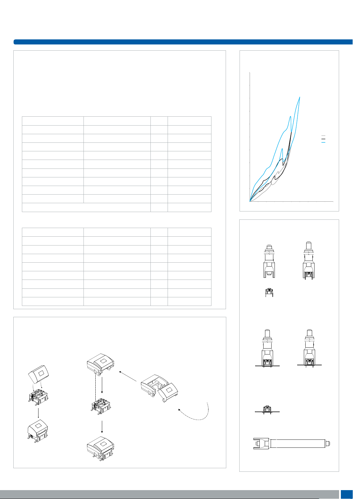
Tape & Reel
Tape and reel is available for the parts
listed and has the following specifications:
Reel diameter: Ø330mm
Tape width: 24mm
Pitch: see list
Tape and reel material: antistatic or
better
Quantity per reel: see list
3C/3E/5E/5G multimec®tape & reel
Part No. Ordering Code Pitch Quantity per reel
3CSH9 3CSH9R 16 500
3ESH9 3ESH9R 16 500
5ESH9XX 5ESH9XXR 16 500
5GSH9XX 5GSH9XXR 16 500
5XSH9XX1SSXX-08.0 5XSH9XXR1SSXX-08.0 20 250
5XSH9XX1SSXX-09.5 5XSH9XXR1SSXX-09.5 20 250
5XSH9XX1SSXX-10.4 5XSH9XXR1SSXX-10.4 20 250
5XSH9XX1SSXX-11.0 5XSH9XXR1SSXX-11.0 20 250
5XSH9XX1SSXX-12.0 5XSH9XXR1SSXX-12.0 20 250
All varimec h <12.5; add R after part no. 20 250
illuminated 5G multimec®tape & reel
Part No. Ordering Code Pitch Quantity per reel
5GSH9XX02 5GSH9XX02R 20 250
5GSH9XX22 5GSH9XX22R 20 250
5GSH9XX42 5GSH9XX42R 20 250
5GSH9XX61 5GSH9XX61R 20 250
5GSH9XX82 5GSH9XX82R 20 250
5GSH9XX2242 5GSH9XX2242R 20 250
5GSH9XX8222 5GSH9XX8222R 20 250
5GSH9XX8242 5GSH9XX8242R 20 250
Operating force
(typical example)
10
force
9
8
7
6
5
F(N)
4
3
2
1
0
0 0,2 0,4 0,6 0,8 1 1,2 1,4 1,6 1,8 2
Mounting tool for multimec® throughhole switches
1. 2.
2N
2N
3,5N
3,5N
6,5N
6,5N
travel
How to assemble
multimec®
5GS+1A/H
multimec®
5GS+1B/C+2C/D
For product updates and/or changes of specifications please see www.apem.com
3. 4.
5.
Part No. 9861000
41
Page 7
multimec®
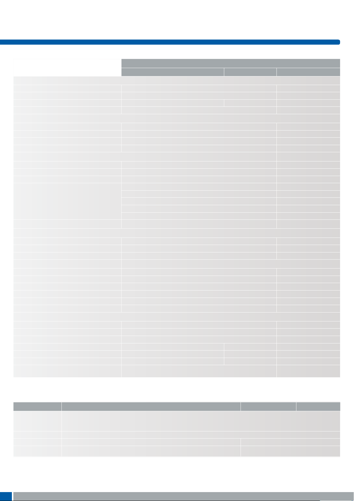
Technical specications
RoHS Compatible
HIGH TEMPERATURE VERSIONS
SILVER GOLD NC/NO
ELECTRICAL SPECIFICATIONS
Contact resistance <30m Ω - typ. 10m Ω
Insulation resistance >10M Ω
Recommended load 0.5-50mA 24VDC 0.5µ-50mA 24VDC
Contact bounce <2mS - typically 0.5mS
MECHANICAL SPECIFICATIONS
Standard actuation force (switch) 2.0N, 3.5N, 6.5 N 3.5N
Max. Actuation force without cap 115N for 60 sec (according to MIL-PRF-22885H) 100N for 10 sec
Key travel (switch) 1 mm
Life time (switch) >10,000,000 cycles >1,000,000 cycles
TEMPERATURE RANGE
Working temperature Min -40°C Max +160°C
Storage temperature Min -40°C Max +160°C
5G with LED (working & storage temp) Min -30°C Max +85°C
Soldering (through-hole switch) IEC 60068-2-20 8:
Infrared, vapour phase, wave - max 240°C for
max 40 sec or max 260°C for max 30 sec.
Soldering iron - max 350°C for max 3 sec.
Flux tight.
SOLDERING (SMD) JEDEC J-STD-020E
ENVIRONMETAL ENDURANCE IEC 68-2-3
Temperature +40°C
Humidity 93% RH
Duration 56 Days
TEMPERATURE CYCLING IEC 68-2-14
Temperature limit Min -55°C - Max +85°C
Number of cycles 200
Exposure time at each temperature 10 min
Recovery time before measurements 16 hrs
Sealing IEC 529 IP-67
Cleaning Standard methods - see usage guidelines
MATERIAL SPECIFICATIONS - SWITCHES
Housing PPS UL94V0
Actuator PPS UL94V0
Sealing + spring Silicone rubber
Contact spring Stainless steel Stainless steel
+ 3µAg + 1µAu
Fixed contacts SnCu + 2µNI + 3µAg SnCu + 2µNI + 1µAu
Terminals SnCu + 2µNI + 3µSn100
5E-5G
Caps, Bezels & Legends – Material Specifications
MATERIAL PARTS TEMP. LIMIT UL R ATING
ABS 1A, 1B, 1C, 1DS, 1ES, 1FS, 1H, 1JS, 1KS, 1LS, 1M, 1NS, 1PS, 1QS, 1RS, 1TS, 1US, 1VS,
1WAS, 1WDS, 1WPS, 1XS, 1Z, 1ZA, 1ZB, 1ZCS, 1ZW, 2C, 2D, 2K, reflectors for
1KBS/1KCS and 1YS
Polycarbonate All lenses and transparent colour caps, lids for 1KBS/1KCS Max. 85⁰C UL94HB
Polyamide 1GAS/1GCS, 1SS, 2SS Max. 160⁰C UL94V2
Legends Adhesion DS/EN ISO 2409 Class 1 & ASTM D3359 Class 4B
For product updates and/or changes of specifications please see www.apem.com
44
Max. 65⁰C UL94HB
Page 8
multimec®
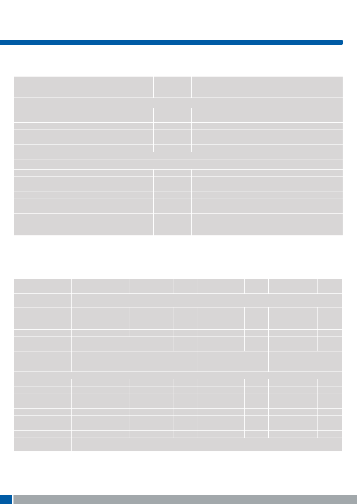
LEDs For 5G and 3F switches
LEDs specifications
5G switches
Colour Blue Green Yellow White Red High Intensity
Green
Colour Codes 02 22 42 61 82 29
ABSOLUTE MAXIMUM RATINGS ( Ta =25 ⁰ C)
Power mW 95 75 60 48 65 102.5
Current forward mA 25 30 25 15 25 25
Forward peak current mA 100 80 60 100 100 150
Voltage reverse V 5 5 5 NA 12 5
Operating temperature ⁰C -40/+85 -55/+85 -40/+85 -40/+85 -30/+85 -40/+85
Storage temperature ⁰C -40/+90 -55/+85 -40/+90 -40/+85 - 40/+85 -40/+85
Soldering temperature ⁰C 245 for max. 10 sec
ELECTRICALOPTICAL CHARACTERISTICS (Ta =25⁰ C)
Voltage forward Typ. V 3.3 2 1.75** 2.85 2 3.3
Max. V 3.7 2.4 2.35 3.1 2.5 4.1
Current reverse (VR=5V) Max. μA 50 100 10 NA 100 50
Wave length nm 470 571 591 NA 633 525
Spread Δnm 25 NA 15 NA 16 30
Spread angle degree 120 130 120 150 160 60
Luminous Intensity Min. mcd 45 18 28.5 71 28 500
Typ. mcd 112* 35 72* 224* 180* 1000
Optical intensity Lm/w NA NA NA 36 7 NA
*Max.mcd **Min. V
3F switches 3FXXX
(for 1E-1F-1N -1Q-1R-1S-1X)
Colour B G Y W R G/Y R/G R/Y G Y R
Colour Codes 00 20 40 65 80 2040 8020 8040 24 46 87
Absolute Maximum
Ratings
Power mW 105 70 60 120 60 120 100 120 60 60 120
Current forward mA 30 20 20 25 20 25 30 25 25 25 50
Forward peak current mA 150 60** 60** 100 60** 150 120 150 60 60 200
Voltage reverse V 5 3 3 5 3 5 5 5 5 5 5
Operating temperature ⁰C -40/+85 -40/+85 -25/+85 -40/+85 -55/+10 0 -40/+85 -40/+85 -40/+85 -40/+85
Storage temperature ⁰C -40/+85 -40 /+100 -30/+10 0 -40/+85 - 55/+100 -40/+85 - 40/+85 -40/+10 0 -40/+10 0
Soldering temperature ⁰C 260 for max 5 sec 260 for max 2 sec 300 for
Electrical-Optical Characteristics (Ta=25C)
Voltage forward Ty p. V 3.8 2.1 2.1 3.8 2.0 2.1 2.0 2.1 2.0* 2.0 2.0***
Current reverse (VR=5V) μA 10 10 10 50 10 2 2 2 10 10 10
Wave length nm 466 563 585 NA 650 565/590 630/565 625/590 570 589 624/632
Spread Δnm 60 40 40 NA 40 35 35 35 10 NA 20
Spread angle degree 60 45 45 25 45 60 200 60 100 40 40
Luminous Intensity Min. mcd 18 9.0 5.6 630 5.6 8 2.2 8 70**** 630 400****
Orientation The longer pin is the anode, the shorter is the cathode.
**Pulse width 1ms Duty cycle 1:5, ***/F =50mA, **** Luminous Flux mlm
B=Blue, G=Green, Y=Yellow, R=Red, W=White
Specifications are subject to change without notice.
(Ta=25⁰C )
Max. V 4.5 3.0 3.0 4.3 3.0 2.8 2.6 2.8 2.4* 2.4 2.4***
Typ. mcd 50 25 16 1000 16 25 4.8 25 20**** 1250 800****
For bicolour LEDs the anode for the first colour (ex. 2080) is the longer pin.
3FXXX
(for 1K-1T-1U-1V-1W-1WD)
260 for max 5 sec
max 3
sec
Specifications are subject to change without notice.
For product updates and/or changes of specifications please see www.apem.com
46
Page 9

Usage guidelines
How to get the best results with MEC Switches?
These guidelines are offered to users of MEC Switches as an aid to
ensure successful and reliable switch operation.
Temperature
Both unimec™ and multimec® switches are produced in low and high
temperature versions. Please see the technical specifications for details on operating and storage temperatures and soldering guidelines
to make sure you select the best switch for your application. When
wave soldering is taking place, MEC strongly recommend that the
temperature profile is analysed and compared with the temperature
rating of the switch. In case of doubt always select the high temperature versions unimec™ 154XX, and multimec® 5XXH9XX. It is also
important to monitor the accumulated heat build up from both the
pre-heat zones and the solder zone.
Most standard accessories for both unimec™ and multimec® switches
are made from ABS plastic with a maximum operating temperature of
65°C. It is strongly recommended that accessories are mounted after
soldering of the switch. If this is not possible care must be taken not
to overheat the accessories during the soldering process. The 1SS,
1GAS/1GCS and Varimec™ caps are, however, made of high temperature materials and will meet the same temperature specifications as
the high temperature switches.
For accessories made from other plastic materials please see multimec® and unimec™ technical specifications.
LEDs have their own temperature specifications. When fitted in a high
temperature switch the LED will determine the max. operating temperature, i.e. 5GTH93524 has an upper temperature limit of 85°C!
This also applies with 3F switches.
Mounting and Dismounting
If switches are to be mounted in rows it is essential that the recommendations regarding spacing are followed. PC board thickness
should be 1.4±0.2 mm and terminal hole diameter should be 0.9mm.
All unimec™ and multimec® caps and bezels are easily snapped onto
the switch modules and can be changed at a later time with the exception of the unimec 16.700 cap. The same applies to the 3E caps. Once
these caps are installed they are not designed to be removed. To do
so may cause damage to the switch and the PC board if not done
very carefully. If the 16.300 or 16.700 cap must be removed from a
unimec™ alternate action switch, make sure that the switch actuator is
in the released, upper position before attempting to remove the cap.
This will prevent possible damage to the internal latching pin.
Care must be taken when inserting the 3FT switch and LED assembly
into the PC board. Do not press direct on the LED. This will force the
LED down into the actuator and risks to cause the switch contacts to
remain in the closed position. To correct the fault, the LED must be
raised slightly and centered in the actuator to assure unrestricted
movement of the actuator. A mounting tool is available for multimec®
switches.
Soldering and Cleaning unimec™
Most assembly and field problems experienced by users of unsealed
switches are caused by the contamination of the contacts during
soldering and cleaning.
Contact contamination may be recognised by an increase in contact
resistance and possible intermittent operation of the switch, especially in low power applications. Care must be taken not to submerge
the switch in cleaning agents or spray the switch during cleaning. The
switch must be protected at all times to prevent contamination by flux
or cleaning liquids.
For unimec™ alternate versions we recommend to leave the actuator in the released upper position during soldering. This makes the
switch more resistent to overheating.
Soldering and Cleaning multimec®
multimec® switches are fully sealed to IP67 specifications to prevent
solder flux and aqueous based cleaning solutions from entering the
switch and contaminating the contacts. The switches can be placed on
the PC board with other components and wave soldered. multimec®
offers a high level of sealing, however, with aqueous solvent solutions care must be taken to avoid the worst case situation with water
jets, complete immersion into a liquid with a temperature below the
board or surface tension reducing additives.
Recommended cleaning methods are demineralized water. Any surface tension reducing agents, such as soap, must not be used as they
risk causing a potential leakage of the switch.
Soldering - Through Hole Versions
Hand soldering: Max. 350°C for max. 3 sec., this applies for both low
temperature and high temperature versions.
Wave soldering: heat built up in the switch during pre-heating and
soldering must not exceed the maximum operating temperature of
the switch. If, for some reason, a high pre-heating temperature is
required, MEC recommend the high temperature switches. In any
case peak temperature must not exceed 260°C, and soldering time
is max 10 sec.
Soldering - Surface Mount Versions
For all methods - infrared, convection and vapour phase. The upper
limit 260°C/30 sec must be observed. The soldering temperature
profile must have moderate temperature gradients.
RoHS Compliance
As of 1 July 2006 MEC has completed the conversion to RoHS compliance. For more info please see our homepage www.apem.com
Temperature Limits:
Low temperature switch 115°C
High temperature switch 160°C
LEDs 85/100°C
Accessories 65/85/160°C
Packaging
unimec™ and multimec® switches are packed in rigid tubes of 50
pieces each.
A box contains 1.000 pcs.
The surface mount versions of multimec®switches with a height up
to 12.5mm can also be delivered on tape/reel. Each reel contains
250/500 pcs.
59
 Loading...