

Page 1

BF series
Paddle controllers
an APEM Group Company
The BF Series Paddle is the very latest generation in high precision contactless controls. It combines the
features of a contactless single axis joystick and a switch in one control. Long trouble-free life is assured
with the latest Hall effect technology, providing a range of analog, switched or custom PWM output
options. The all-new design with its innovative mechanism and ergonomic styling is specifically
designed for robustness, strength and performance.
A
KEY FEATURES
Hall effect joystick and switch function
Sculpted ergonomic design
Next generation Hall effect technology
5V operation - dual redundant
outputs as standard
Two lever height variants
Industry standard connector
IP67 sealed
Sprung and detent lever options
Available with color-coded inserts
EMC & Magnetically shielded
- analog or PWM outputs
Effectively zero below panel depth
End stackable mounting
www.chproducts.com
Page 2
BF series
Paddle controllers
OPTION SELECTION
PADDLE
BF 74mm (2.91in)
above the panel
BD 50mm (1.97in)
above the panel
CONFIGURATION
1 Standard Dual Outputs
2 Inverse Dual Outputs
3 PWM
GAIN
10 +/-10% x V
25 +/-25% x V
30 +/-30% x V
40 +/-40% x V
50 +/-50% x V
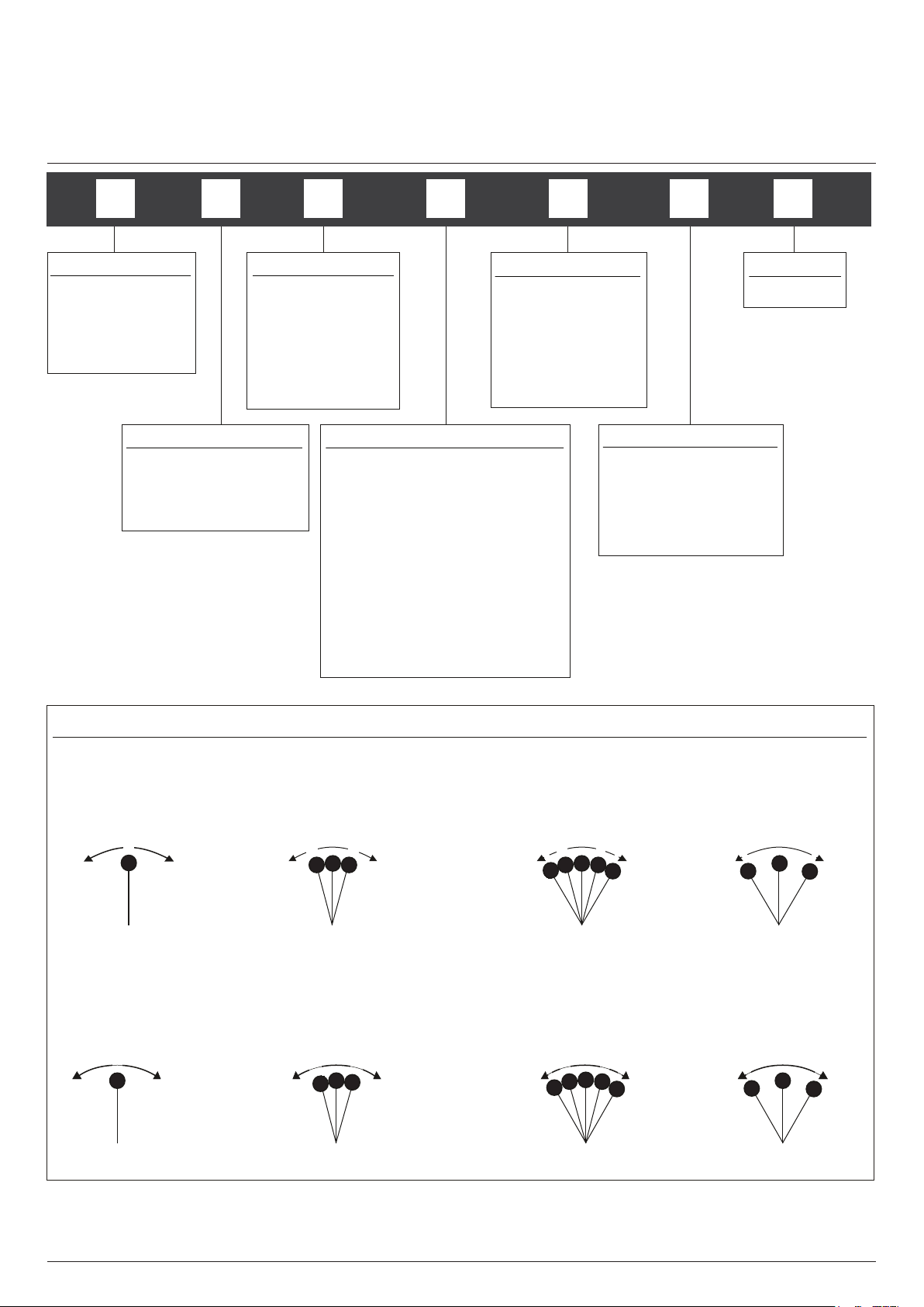
LEVER OPERATION
A01 Sprung to Center
D01 Center Detent
D02 12.5 Degree Detents
D03 12.5 & 25 Degree Detents
D04 25 Degree Detents
SD1 Sprung to Center with D1
SD2 Sprung to Center with D2
SD3 Sprung to Center with D3
SD4 Sprung to Center with D4
INSERT COLOR
BK Black
RE Red
BL Blue
YE Yellow
GR Green
SWITCHING POINTS
00 No Switches
05 +/- 5 Degrees
12 +/- 12.5 Degrees
25 +/- 25 Degrees
MODIFIER
00 None
LEVER OPERATION
DETENT OPTIONS
D01 = CENTER DETENT D02 = +/-12.5 DEGREES D03 = +/- 12.5 & 25 DEGREES D04 = +/-25 DEGREES
SPRUNG TO CENTER WITH DETENT OPTIONS
SD1 = CENTER DETENT SD2 = +/-12.5 DEGREES SD3 = +/- 12.5 & 25 DEGREES SD4 = +/- 25 DEGREES
Note: The company reserves the right to change specifications without notice.
www.chproducts.com
Page 3

BF series
Paddle controllers
SPECIFICATIONS
MECHANICAL
Materials Employed – Polyetherimide, Polycarbonate, Stainless Steel
Weight – 50g
Mechanical Operating Angle – +/- 25 Degrees
Max Load to Mechanism – Vertical: IK08 (BSEN62262:2002)
Horizontal: 75N (16.86lbf)
ELECTRICAL
Gain (Output Voltage Span) – +/-10% x V to +/-50% x V
Output at Center – V/2 +/- (5% x Gain)
Power Supply – 5V +/-0.5V Transient free
Switch Outputs – Open Drain, pulled high within control via 1K5 to 5V,
and smoothed to 0V with 100nF
Sensor Type – Hall effect
Current Consumption – <20mA
Loads – Minimum 10K, preferred 100K+
ENVIRONMENTAL
Storage – -40°C to 70°C (-40°F to 158°F)
Operating Temperature – -25°C to 70°C (-13°F to 158°F)
Seal Above Panel – IP67 (Gasket fitted as standard)
EMC Emissions – Complies with EN 61000-6-3:2001 CISPR 22:2005 Class
B 30MHz - 11GHz
Life Cycles – 5 million cycles sprung version only. Detents rated to
2 million cycles
ESD – Complies with EN61000-4-2 (extended)
+/-8KV (20 contacts) & +/-15KV (20 air discharges)
EMC Immunity – 100V/m, 80MHz-2.7GHz, 1KHz 80% sine wave
modulation, EN 61000-4-3 (extended)
Vibration – 100Hz - 200Hz @ 0.13g²/Hz, total 3.6gRMS (1 Hour in
each of the three mutually perpendicular axes)
A
All parameters shown are based on a standard configuration and are provided for guidance only.
Please refer to Apem for assistance on how to achieve the best performance from your chosen configuration.
Note: The company reserves the right to change specifications without notice.
www.chproducts.com
Page 4
50.00
(1.97)
36.00
(1.42)
Ø3.00
(0.12)
33.00
(1.30)
BF series
Paddle controllers
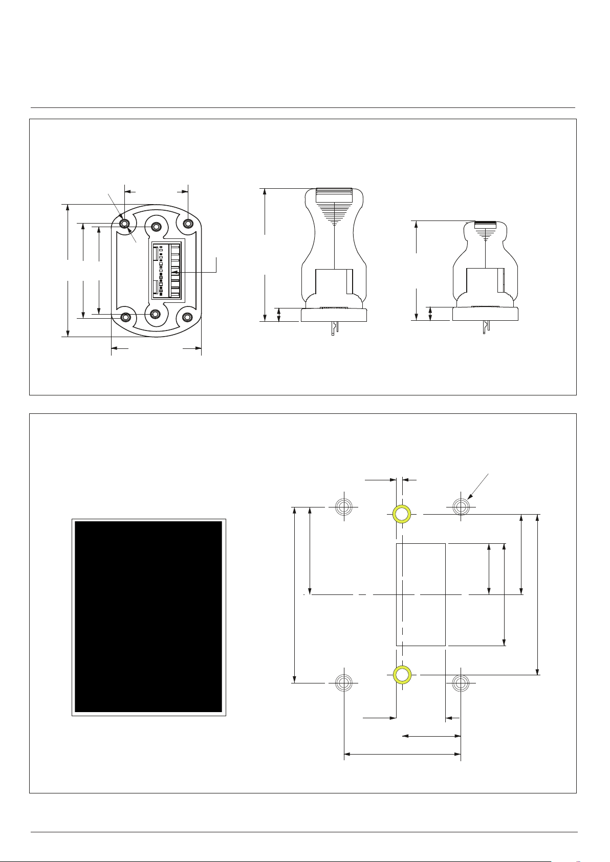
DIMENSIONAL DRAWINGS
GENERAL DIMENSIONS
BF
24.00
(0.95)
BD
(1.00)
2.54 PITCH
8 WAY CONNECT OR
34.00
(1.34)
74.00
(2.91)
7.50
(0.30)
50.00
(1.97)
7.50
(0.30)
DROP IN MOUNTING - PANEL CUT-OUT & MOUNTING INSTALLATION
The Paddle may be mounted with two different hole patterns:
- Two screws - in line on the Y axis (shown as yellow screws)
- Four screws - one in each corner (shown as silver screws)
18.00
(0.71)
36.00
(1.42)
1.20
(0.05)
10.00
(0.39)
10.50
(0.41)
Ø3.20
(0.13)
21.00
(0.83)
16.50
(0.65)
33.00
(1.30)
12.00
(0.47)
24.00
(0.94)
The Paddle is fitted with M3 bushes in all six positions, as standard.
Fasteners are not supplied as standard. The appropriate length of fastener is dependent on panel thickness.
NOTE: All dimensions in mm/(inch).
Note: The company reserves the right to change specifications without notice.
www.chproducts.com
Page 5
BF series
Paddle controllers
MECHANICAL & CONNECTION INFORMATION
MECHANISM
The brand new mechanism design has been developed for strength and long life while retaining a superb feel.
SPRUNG TO CENTER
The lever springs back to the center position when released.
DETENT POSITIONS
A
The lever ‘clicks’ into a number of preset positions. The internal switches can be configured to trigger
at two of these points
DETENT POSITIONS WITH SPRUNG TO CENTER
The lever ‘clicks’ into a number of preset positions and springs back to its center position when released.
CONNECTIONS
The Paddle is fitted, as standard, with an industry standard 2.54mm pitch 8 way connector.
CONNECTIONS
PIN 1:
PIN 2:
PIN 3:
PIN 4:
PIN 5:
PIN 6:
PIN 7:
PIN 8:
5V
Switch 1(+)
0V
Analog/PWM output 1
Analog/PWM ouptut 2
0V
Switch 2 (-)
5V
Paddles are supplied with an eight way connector as standard.
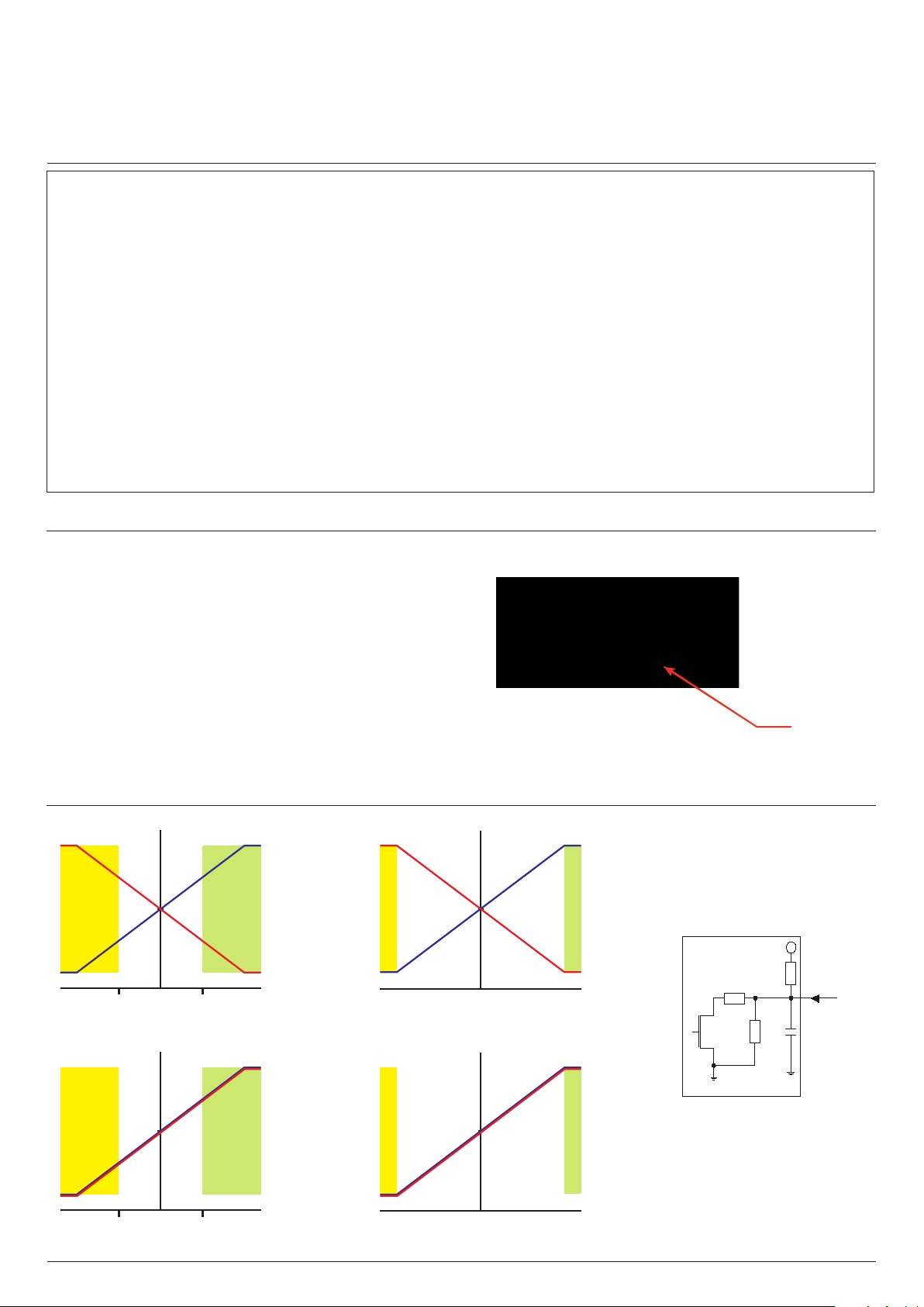
BF SERIES OUTPUT CHARACTERISTICS - 40% GAIN DUAL INVERSE OUTPUTS
Switches at 12.5 Degrees
4.5V
4
3
Switch 2
On
2.5
2
1
0.5
10
0 2520
-10-20-25
-12.5 12.5
Switches at 12.5 Degrees
4.5V
4
O utput1
Switch 1
On
O utput2
Degree s Deection
40% GAIN DUAL OUTPUTS
O utput1
O utput2
Switches at 25 Degrees
4.5V
4
3
2.5
Switch 2 On
2
1
0.5
Switches at 25 Degrees
4.5V
4
O utput1
Switch 1 On
O utput2
0 252010-10-20-25
Degree s Deflection
O utput1
O utput2
Equivalent circuit for the switch output
1
PIN 1
5V
1k5
SWITCH
175
Ω
Ω
Ω
6k
125
OUTPUT
10mA
Max
100 nF
3
2.5
2
1
0.5
0 252010-10-20-25
Switch 2
Off
-10-20-25
-12.5 12.5
3
2.5
2
1
0.5
10
0 2520
Switch 1
On
Switch 2 Off
Degree s Deection
Note: When Dual Output (non-inverted) option is selected the polarity of Switch 2 is inverted
Note: The company reserves the right to change specifications without notice.
www.chproducts.com
Switch 1 On
Degree s Deflection
Page 6

BF series
Paddle controllers
CONFIGURATION OPTIONS
OUTPUT OPTIONS
The BF Series Paddle is configured as two “electrical” controls in one mechanical package. The Paddle operates from 5V and provides two proportional outputs. The second output is accurate to the first within +/-3% of
the power supply. The power supply for the secondary output is also completely independent. Customers may
choose their preference of voltage outputs (gains).
The secondary output can be of the same or inverse polarity to the primary wiper. For example, with a
secondary inverse output, the first and second outputs can be summed and compared to zero to verify that the
joystick is operating correctly. Paddles having two identical outputs of the same polarity may be used to drive
two identical dual redundant circuits.
There are also two Hall effect switches that trigger at pre-determined lever positions.
The BF Series Paddle may be specified with a variety of PWM output options. For more details on available
PWM options please refer to Apem.
ADDITIONAL OUTPUT INFORMATION
SELECTABLE SWITCHING POINTS
The Paddle incorporates two Hall effect switches. The angle of the lever at the switch trigger point can be
selected when ordering.
If no switches are specified then the output on pins 2 and 7 will be unused.
The outputs are configured as ‘open drain’ type with a 1K5 pull up resistor to 5V.
GAIN OPTIONS
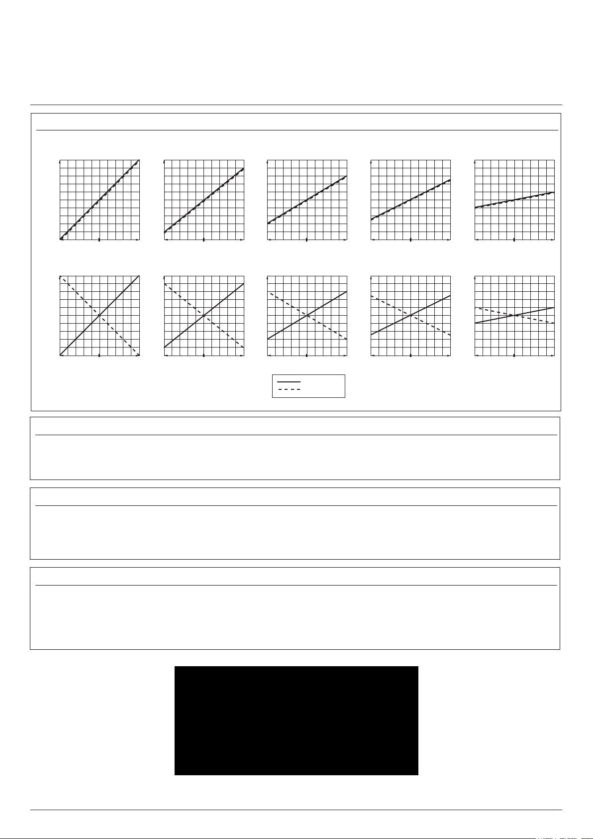
The voltage output on the wiper, at full scale deflection is determined by the gain. The gain is expressed as a
percentage of the voltage supplied. Therefore (assuming a 5V supply) a Paddle specified with +/- 25% gain
would yield 1.25V at South, 2.5V at center and 3.75V at North. A range of gain options are available as
standard. All controls are supplied pre-set and no further calibration is needed throughout the lifetime of
operation.
OUTPUT IMPEDANCE
The voltage outputs at center and at each end of travel are specified across an infinite load, with no current
flowing. The output impedance specified in the electrical specification should be taken into account when
designing a system. Load resistance of less than 10K Ohms is not recommended.
HANDLE OPTIONS
The BF Series offers two standard handle options. The taller (74mm) handle provides the most ergonomic
solution while the shorter (50mm) is best suited to hand held applications where a minimized height is
preferred. The taller lever is supplied with the top insert prefitted, however the shorter lever may be specified
with no insert fitted and the snap in inserts supplied loose for ease of customer integration.
Note: The company reserves the right to change specifications without notice.
www.chproducts.com
Page 7
BF series
Paddle controllers
APPLICATION DETAILS
LINEAR OUTPUT OPTIONS
(+2.5) 5.0
(+2.0) 4.5
(+1.5) 4.0
(+1.0) 3.5
(+0.5) 3.0
(+0.0) 2.5
(- 0.5) 2.0
(- 1.0) 1.5
OUTPUT VOLTAGE (V)
(- 1.5) 1.0
(- 2.0) 0.5
(- 2.5) 0.0
+/-50% +/-40% +/-30% +/-25% +/-10%
MIN AXES TRAVEL (º) MAX MIN AXES TRAVEL (º) MAX
(+2.5) 5.0
(+2.0) 4.5
(+1.5) 4.0
(+1.0) 3.5
(+0.5) 3.0
(+0.0) 2.5
(- 0.5) 2.0
(- 1.0) 1.5
(- 1.5) 1.0
(- 2.0) 0.5
(- 2.5) 0.0
DUAL OUTPUT - CONFIGURATION 3
(+2.5) 5.0
(+2.0) 4.5
(+1.5) 4.0
(+1.0) 3.5
(+0.5) 3.0
(+0.0) 2.5
(- 0.5) 2.0
(- 1.0) 1.5
(- 1.5) 1.0
(- 2.0) 0.5
(- 2.5) 0.0
MIN AXES TRAVEL (º) MAX
DUAL OUTPUT - CONFIGURATION 4
(+2.5) 5.0
(+2.0) 4.5
(+1.5) 4.0
(+1.0) 3.5
(+0.5) 3.0
(+0.0) 2.5
(- 0.5) 2.0
(- 1.0) 1.5
OUTPUT VOLTAGE (V)
(- 1.5) 1.0
(- 2.0) 0.5
(- 2.5) 0.0
+/-50% +/-40% +/-30% +/-25% +/-10%
MIN AXES TRAVEL (º) MAX MIN AXES TRAVEL (º) MAX
(+2.5) 5.0
(+2.0) 4.5
(+1.5) 4.0
(+1.0) 3.5
(+0.5) 3.0
(+0.0) 2.5
(- 0.5) 2.0
(- 1.0) 1.5
(- 1.5) 1.0
(- 2.0) 0.5
(- 2.5) 0.0
(+2.5) 5.0
(+2.0) 4.5
(+1.5) 4.0
(+1.0) 3.5
(+0.5) 3.0
(+0.0) 2.5
(- 0.5) 2.0
(- 1.0) 1.5
(- 1.5) 1.0
(- 2.0) 0.5
(- 2.5) 0.0
MIN AXES TRAVEL (º) MAX
Output 1
Output 2
POWER SUPPLY
(+2.5) 5.0
(+2.0) 4.5
(+1.5) 4.0
(+1.0) 3.5
(+0.5) 3.0
(+0.0) 2.5
(- 0.5) 2.0
(- 1.0) 1.5
(- 1.5) 1.0
(- 2.0) 0.5
(- 2.5) 0.0
MIN AXES TRAVEL (º) MAX
(+2.5) 5.0
(+2.0) 4.5
(+1.5) 4.0
(+1.0) 3.5
(+0.5) 3.0
(+0.0) 2.5
(- 0.5) 2.0
(- 1.0) 1.5
(- 1.5) 1.0
(- 2.0) 0.5
(- 2.5) 0.0
MIN AXES TRAVEL (º) MAX
(+2.5) 5.0
(+2.0) 4.5
(+1.5) 4.0
(+1.0) 3.5
(+0.5) 3.0
(+0.0) 2.5
(- 0.5) 2.0
(- 1.0) 1.5
(- 1.5) 1.0
(- 2.0) 0.5
(- 2.5) 0.0
MIN AXES TRAVEL (º) MAX
(+2.5) 5.0
(+2.0) 4.5
(+1.5) 4.0
(+1.0) 3.5
(+0.5) 3.0
(+0.0) 2.5
(- 0.5) 2.0
(- 1.0) 1.5
(- 1.5) 1.0
(- 2.0) 0.5
(- 2.5) 0.0
MIN AXES TRAVEL (º) MAX
The BF Series is designed to be powered by a regulated 5V+/- 0.5V power supply. The outputs are ratiometric, making a
stable, noise free, power supply essential. The power supply to the joystick should be carefully regulated to be within
tolerance. Should the power supply change outside of the specified tolerances, permanent damage may occur.
MAGNETIC IMMUNITY AND SYSTEM DESIGN
The BF Series incorporates internal magnetic screening to minimize the effect of external magnetic fields. Mounting or
operating the Paddle close to strong magnetic fields is not recommended. System designers should follow best practice when
incorporating the BF Series Paddle into their products. Care should be taken to decouple the power supply properly and to
employ adequate EMC shielding.
MOUNTING
When mounting the Paddle, care should be taken to site it in a position that does not make it vulnerable to damage when in
use. If the Paddle is intended for use in a handheld enclosure then care must be taken to protect the Paddle from damage
caused by dropping. Basic precautions such as mounting it at the lightest end of the enclosure so it doesn’t hit the ground
first or by protecting it with a guard should always be implemented for long term reliability. The body of the Paddle, on the
underside of the panel, must not be subject to water spray, excessive humidity or dust.
.
Note: The company reserves the right to change specifications without notice.
www.chproducts.com
 Loading...