

Page 1
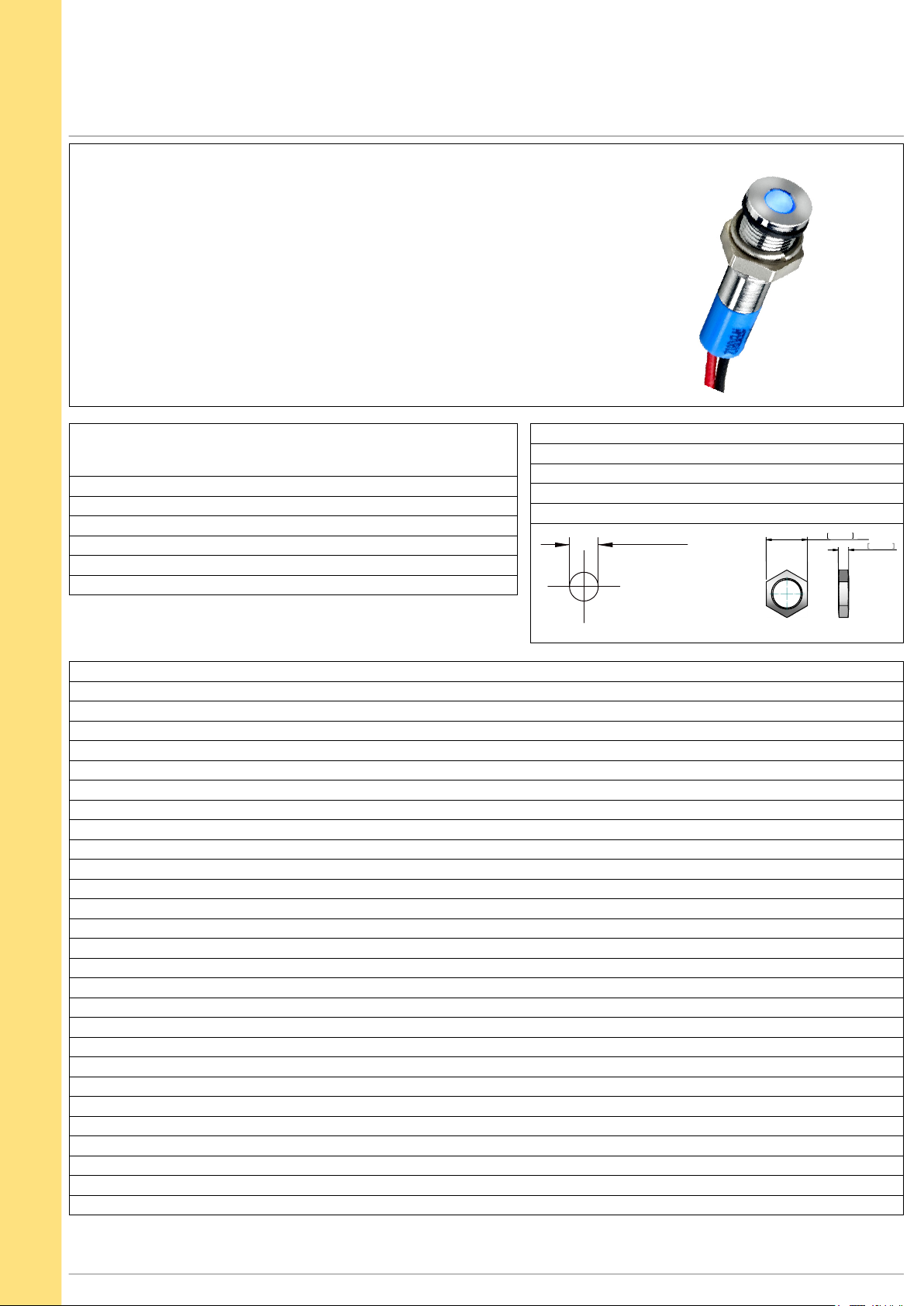
Q SERIES Ø6mm (.236") Panel Mount LED Indicators
8,00 0,315 AF
2,00 0,079
M6 x 0,50 THREAD
Distinctive features and specification
Features
• 6mm panel mounting LED indicator
• 3mm colored diffused epoxy lens or 3mm water clear super bright LEDs
•
Plated brass bezel finished in bright chrome,
black chrome or satin grey and moulded polycarbonate rear body
• Prominent, recessed and flush bezel styles
• 2VDC – 28VDC
• (2.0 x 0.5) solder lug terminals, pins or (200mm long) wire terminations
• IP67 sealing option (EN60529)
• Supplied with fixing nut and spring washer
NB: UL Recognized Component
VOYC1603R1US
TECHNICAL SPECIFICATIONS
Voltage Operating Voltage Operating Current
(Min to Max) (Typical All Types)
02 (No Resistor) 1.8 to 3.8VDC 20mA max*
6VDC 5.4 to 6.6VDC 20mA
12VDC 10.8 to 13.2VDC 20mA
24VDC 21.6 to 26.4VDC 20mA
28VDC 25.2 to 30.8VDC 20mA
Standard LED Intensity Prominent and Recessed
Max Reverse Voltage: 5V
Viewing Angle: 30–100°
(dependant on model)
Life Expectancy: 100,000 hours
Temperature Range: –40 to +85°C
Torque:
4cNm
Ø 6.00 +0.15/-0.0
PANEL CUTOUT
Flush Forward Voltage
(operating & storage)
HE Red 40mcd 10mcd 2.0V
Green 50mcd 12mcd 2.2V
Yellow 30mcd 6mcd 2.1V
Blue 1,200mcd 100mcd 3.8V
White 1,200mcd 160mcd 3.8V
Orange 60mcd 10mcd 2.0V
Bi-color (Typical) (Red/Green) 20/15mcd 10/8mcd 2.0V/2.2V
The color is changed by reversing the polarity of the supply voltage.
Super Bright LED Prominent and Recessed Flush Forward Voltage
HE Red 1,000mcd 700mcd 2.2V
Green 1,200mcd 2,000mcd 3.5V
Yellow 2000mcd 8,000mcd 2.3V
Blue 1,600mcd 200mcd 3.3V
White 1,200mcd 350mcd 3.3V
Orange 10,000mcd 500mcd 2.2V
Hyper Bright LED Prominent and Recessed Flush Forward Voltage
HE Red 3,700mcd 600mcd 2.2V
Green 2,000mcd 350mcd 3.2V
Yellow 1,200mcd 140mcd 2.0V
Orange
4,500mcd
400mcd
2.2V
Note: The operating vo ltage must not b e exceeded by more t hat 10% as this will result in reduced life expectancy.
The company reserves t he right to change specifications without notice.
* Customer to supply resi stor f or desired operatin g current .
Luminous i ntensity is me
asured at 20mA on a d iscrete LED unless o therwise stated.
Luminous intensity will be reduced with lower operating current.
APEM
www.apem.com
1
Page 2
Q SERIES Ø6mm (.236") Panel Mount LED Indicators
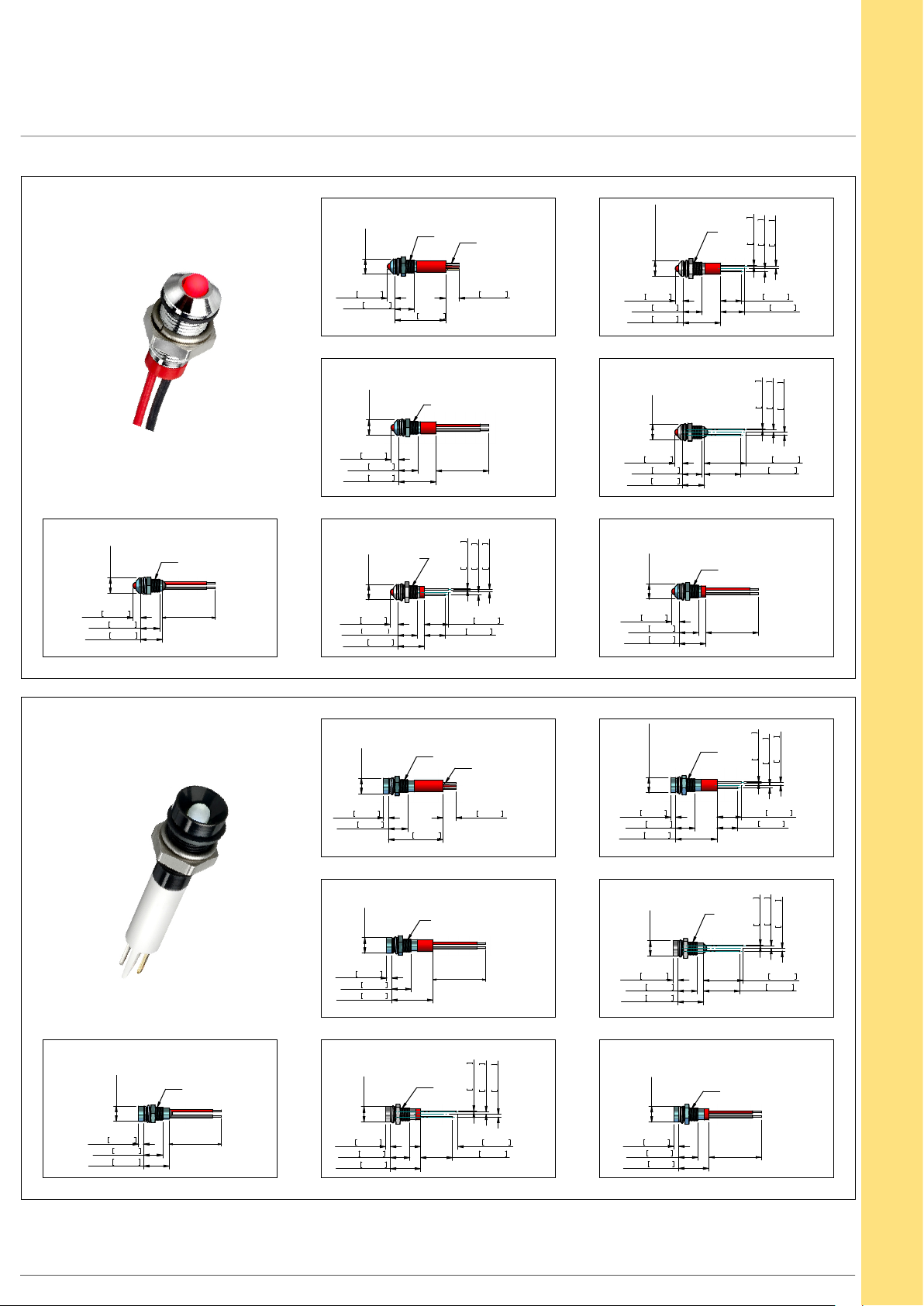
Technical Drawings
PROMINENT BEZEL
REAR E POXY WIRES
7,00
[0,275]
3,50 0,138
8,75 0,344
10,00 0,394
M6 x0,5
200,00+/-10
[7,874+/-0,393]
7,00
[0,275]
3,50 0,138
8,75 0,344
7,00
3,50 0,138
8,75 0,344
17,10 0,673
7,00
3,50 0,138
8,75 0,344
12,00 0,472
[0,275]
[0,275]
23,10 0,909
M6x0,5
M6x0,5
6,00 0,236
M6x0,5
200,0+/-10
[7,874+/-0,393]
SHORT BODY PINS
0,50 0,020
11,00 0,433
9,50 0,374
SOLDER LUG
2,0x0,5[0,078x0,02]
WIRES
1,25 0,049
1,25 0,049
3,50 0,138
17,10 0,673
7,00
[0,275]
3,50 0,138
8,75 0,344
10,00 0,394
7,00
[0,275]
3,50 0,138
8,75 0,344
12,00 0,472
7,00 [0,275]
M6x0,5
0,50 0,020
9,50 0,374
11,00 0,4338,75 0,344
REAR E POXY PINS
18,98 0,747
16,60 0,654
SHORT BODY WIRES
M6x0,5
200,0+/-10
[7,874+/-0,393]
0,50 0,020
1,25 0,049
1,25 0,049
PINS
1,25 0,049
1,25 0,049
RECESSED BEZEL
REAR E POXY WIRES
7,00
[0,275]
2,25 0,089
8,75 0,344
11,65 0,459
M6 x0,5
200,0+/-10
[7,874+/-0,393]
7,00
[0,275]
2,25 0,089
8,75 0,344
7,00
[0,275]
2,25 0,089
8,75 0,344
18,75 0,738
7,00
[0,275]
2,25 0,089
8,75 0,344
13,65 0,537
24,75 0,974
M6x0,5
6,00 0,236
M6x0,5
200,0+/-10
[7,874+/-0,393]
SHORT BODY PINS
M6x0,5
16,98 0,668
14,60 0,575
SOLDER LUG
2,0x0,5[0,078x0,02]
WIRES
0,50 0,020
1,25 0,049
1,25 0,049
7,00[0,275]
2,25 0,089
8,75 0,344
18,75 0,738
7,00
[0,275]
2,25 0,089
8,75 0,344
11,65 0,459
7,00
[0,275]
2,25 0,089
8,75 0,345
13,65 0,537
M6x0,5
0,50 0,020
11,00 0,433
9,50 0,374
REAR E POXY PINS
M6 x0,5
0,50 0,020
18,10 0,713
16,60 0,654
SHORT BODY WIRES
M6x0,5
200,0+/-10
[7,874+/-0,393]
1,25 0,049
1,25 0,049
PINS
1,25 0,049
1,25 0,049
2
www.apem.com APEM
Page 3
Q SERIES Ø6mm (.236") Panel Mount LED Indicators
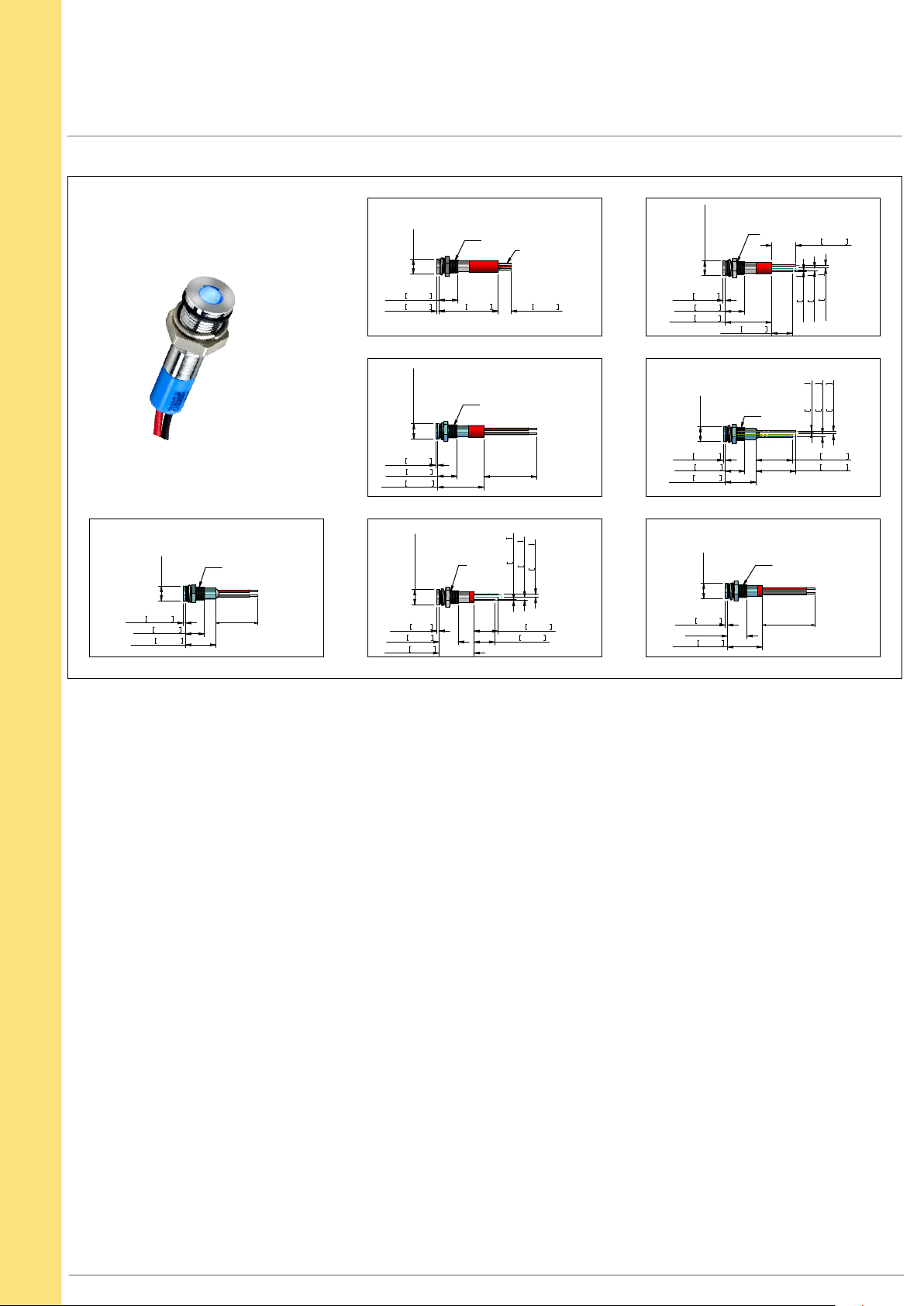
Technical Drawings
FLUSH BEZEL
7,00
[0,275]
1,00 0,039
8,75 0,344
13,90 0,547
M6 x0,5
200,0+/-10
[7,874+/-0,393]
7,00
[0,275]
8,75 0,344
1,00 0,039
7,00 [0,275]
1,00 0,039
8,75 0,344
21,00 0,827
7,00 [0,275]
1,00 ,039
8,75 0,344
15,90 0,626
27,00 1,063
M6x0,5
M6x0,5
6,00 0,236
M6x0,5
200,0 +/-10
[7,874+/-0,393]
0,50 0,020
11,00 0,433
9,50 0,374
SOLDER LUG
2,0x0,5 [0.078x0.02]
WIRES
1,25 0,049
1,25 0,049
7,00 [0,275]
1,00 0,039
8,75 0,344
21,00 0,827
7,00
[0,275]
1,00 0,039
8,75 0,344
13,90 0,547
7,00
[0,275]
1,00 0,039
8,75 0,344
15,90 0,626
9,50 0,374
M6x0,5
11,00 0,433
REAR E POXY PINS
M6 x0,5
16,60 0,654
18,10 0,713
SHORT BODY WIRESSHORT BODY PINSREAR E POXY WIRES
M6x0,5
200,0 +/-10
[7,874 +/- 0,393]
0,50 0,020
0,50 0,020
1,25 0,049
1,25 0,049
PINS
1,25 0,049
2,50 0,098
APEM
www.apem.com
3
Page 4
Q SERIES Ø6mm (.236") Panel Mount LED Indicators
Overview
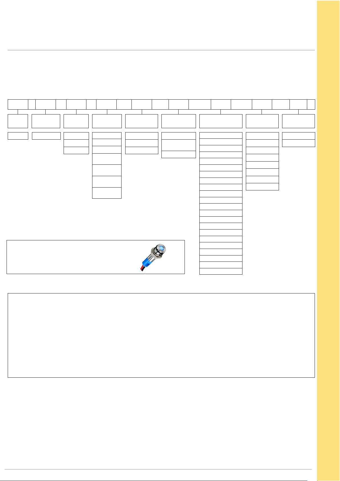
STANDARD OPTIONS
The Q6 Series is available with a range of standard options, to specify your LED, simply choose one option from each
column. An example is shown below.
Q 6 P 1 B XX G 12 E
SERIES
Q
MOUNTING
HOLE
6 = Ø6mm
BEZEL
STYLE
P = Prominent
R = Recessed
F = Flush
Example Q6F3CXXB12E
Ø6mm, flush bezel, wire terminals
bright chrome finish, fixed light,
blue, 12VDC LED, IP67 panel sealed
TERMINALS BEZEL FINISH
1 = Solder Lug
2 = Pins
3 = Wires
4 = Rear epoxy
Pins
5 = Rear epoxy
Wires
6 = Short body
Pins
7 = Short body
Wires
C = Bright Chrome
B = Black Chrome
G = Satin Grey
TYPE OF
ILLUMINATION
XX = Fixed Light
KK = Flashing Light
(12V – 28VDC)
YY = Bi-color
LED COLOR VOLTAGE SEALING
R = Red
G = Green
Y = Yellow
B = Blue
W = White
O = Orange
HR = Hyper Bright Red
HG = Hyper Bright Green
HY = Hyper Bright Yellow
HO = Hyper Bright Orange
SR = Super Bright Red
SG = Super Bright Green
SY = Super Bright Yellow
SB = Super Bright Blue
SW = Super Bright White
SO = Super Bright Orange
RG = Red/Green
RY = Red/Yellow
GY = Green/Yellow
02 = no resistor*
06 = 6VDC
12 = 12VDC
12A = 12VAC/DC
24 = 24VDC
24A = 24VAC/DC
28 = 28VDC
28A = 28VAC/DC
(Blank) = Unsealed
E = IP67
• Gold solder lug terminal denotes Anode (+), silver terminal denotes Cathode (-)
• Standard wire length is 200mm, 24AWG UL 1061, red wire denotes Anode (+), black wire denotes Cathode (-)
for other wire lengths consult APEM
• For LEDs with alternative voltages consult APEM
• Bi-color LEDs, by connecting the gold solder lug (+) one color is produced,
by reversing the supply voltage another color is produced – Bi-colors are available up to 28VDC
• Take care when soldering to the terminals (recommended solder temperature 300°C - 3 sec)
• Short body options are only available up to 24VDC
• Maximum panel thickness 7mm
* = For resistorless versions (02) please refer to the forward voltage on page 1
4
www.apem.com
APEM
 Loading...