

Page 1
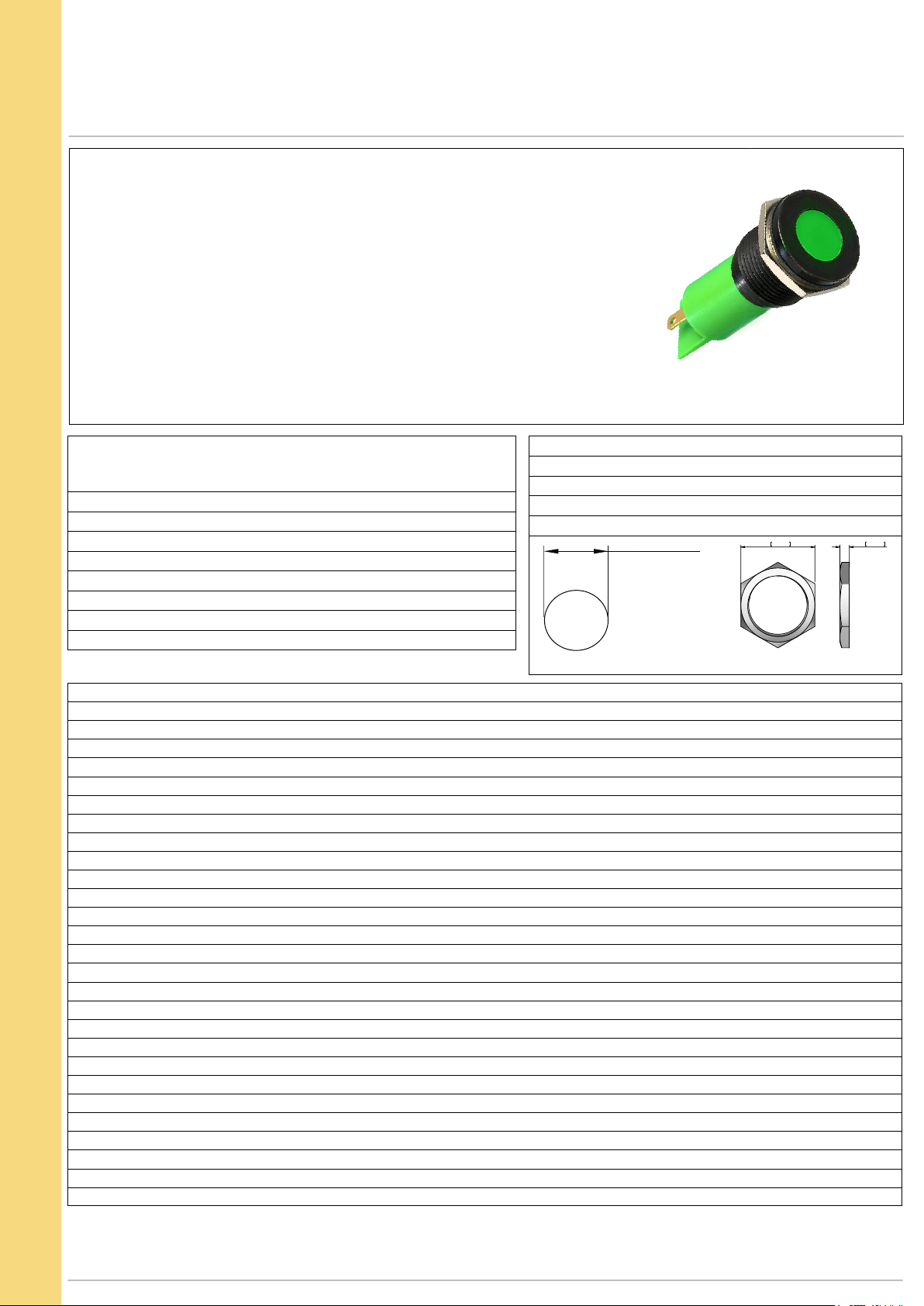
Q SERIES Ø16mm (.630") Panel Mount LED Indicators
19,00 0,748 AF
2,40 0,094
M16 x 1,0 THREAD
Distinctive features and specification
Features
• 16mm panel mounting LED indicator
• 10mm colored diffused epoxy lens or 10mm water clear super bright LEDs
Plated brass bezel finished in bright chrome,
•
black chrome or satin grey and moulded polycarbonate rear body
•
Secret until lit polycarbonate decals or custom engraving
• Prominent and flush bezel styles
• 2VDC – 220VAC
• (2.8 x 0.8) solder lug/faston terminals, pins or (200mm long) wire terminations
IP67 sealing option (EN60529)
•
• Supplied with fixing nut and spring washer
NB: UL Recognized Component
Max Reverse Voltage: 5V
TECHNICAL SPECIFICATIONS
Voltage Operating Voltage Operating Current
(Min to Max) (Typical All Types)
02 (No Resistor) 1.8 to 3.3VDC 20mA max*
6VDC 5.4 to 6.6VDC 20mA
12VDC 10.8 to 13.2VDC 20mA
24VDC 21.6 to 26.4VDC 20mA
28VDC 25.2 to 30.8VDC 20mA
110VAC 99 to 121VAC 6mA
220VAC 207 to 253VAC 3mA
Viewing Angle: 30–100°
Life Expectancy: 100,000 hours
Temperature Range: –40 to +85°C
Torque:
75cNm
Ø 16.00 +0.15/-0.0
PANEL CUTOUT
(dependant on model)
(operating & storage)
VOYC1603R1US
Standard LED Intensity Prominent Flush Forward Voltage
HE Red 80mcd 10mcd 2.0V
Green 60mcd 5mcd 2.2V
Yellow 50mcd 4mcd 2.1V
Blue 540mcd 100mcd 3.3V
White 1000mcd 150mcd 3.3V
Orange 80mcd 200mcd 2.0V
Bi-color (Typical) (Red/Green) 15/15mcd 10/10mcd 2.0V/2.2V
Tri-color (Typical) (Red/Green/Yellow) 60/50/50mcd 15/30/30mcd 2.0V/2.2V/2.1V
Bi-color - The color is changed by reversing the polarity of the supply voltage.
Tri-color - The indicator has red and green LEDs, when both connected yellow is produced.
Super Bright LED Prominent Flush Forward Voltage
HE Red 17,000mcd 2000mcd 2.2V
Green 11,000mcd 680mcd 3.5V
Yellow 4,000mcd 350mcd 2.3V
Blue 2,500mcd 250mcd 3.3V
White 4,400mcd 250mcd 3.3V
Orange 2,800mcd 300mcd 2.1V
Hyper Bright LED Prominent Flush Forward Voltage
HE Red 2,800mcd 800mcd 2.1V
Green 2,200mcd 250mcd 3.2V
Yellow 1,300mcd 250mcd 2.0V
Orange
Luminous intensity will be reduced with lower operating current.
850mcd
200mcd 2.1V
Note: The operating voltage must not be exceed ed by more that 10% as this will result in reduced life expectanc y.
The company reserves the right to cha nge s pecifications without notice.
* Customer to supply resistor for desired operating current.
Luminous i ntensity is measured at 20mA on a dis crete L ED unless o therwise stated.
Luminous i ntensities and color shades of white LEDs m ay vary within a batch.
APEM
www.apem.com
1
Page 2
www.apem.com
Q SERIES Ø16mm (.630") Panel Mount LED Indicators
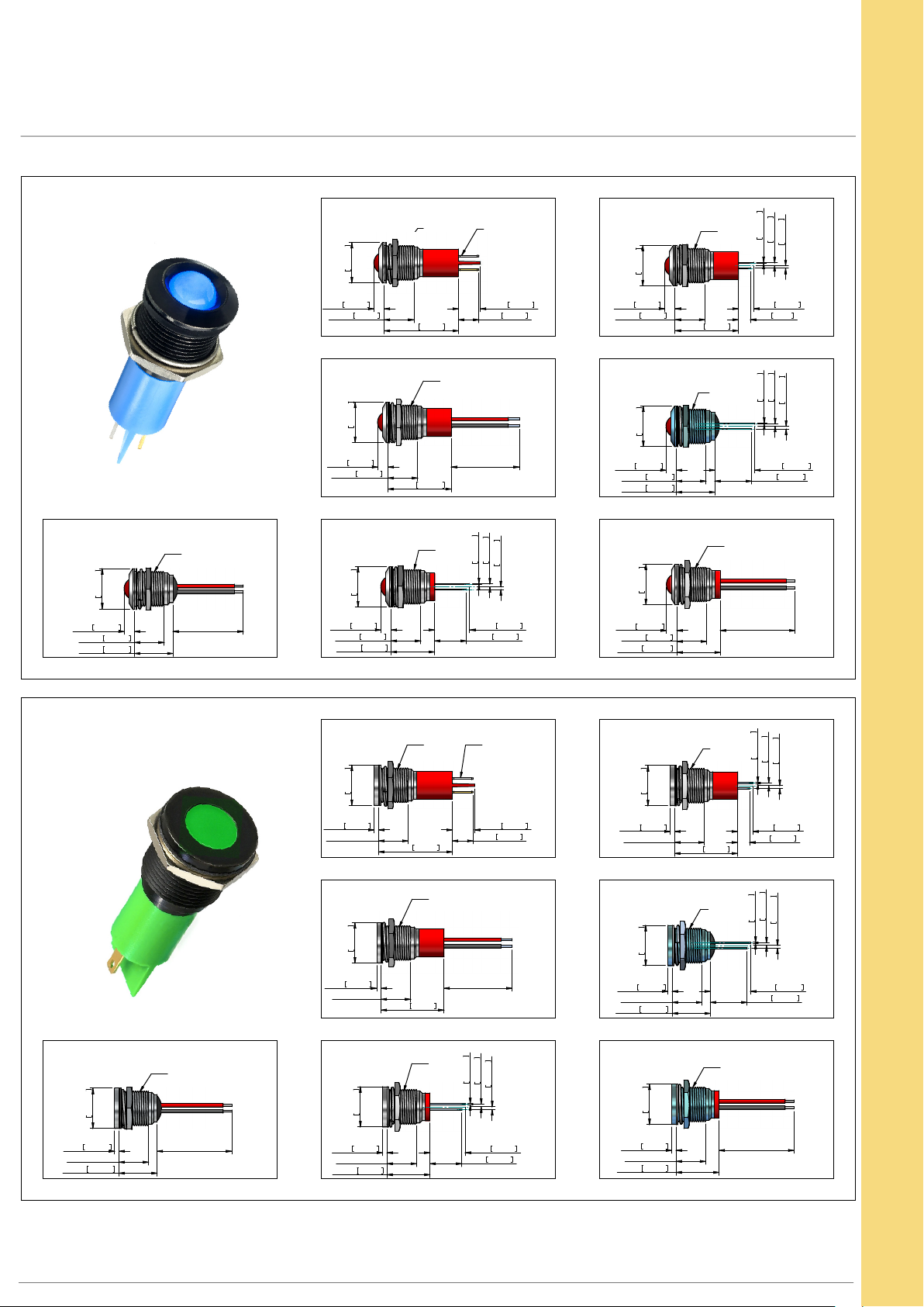
Technical Drawings
PROMINENT BEZEL
REAR E POXY WIRES
M16x1,0
18,30
0,720
4,75 0,187
13,50 0,531
17,50 0,689
200,0+/-10
[7,874+/-0,393]
18,30
0,720
4,75 0,187
13,50 0,531
18,30
0,720
4,75 0,187
13,50 0,531
18,30
4,75 0,187
13,50 0,531
19,75 0,778
0,50 0,020
PINS
1,25 0,049
1,25 0,049
SOLDER LUG/FASTONS
M16x1,0
2,8x0,8[0,11x0,031]
M16x1,0
18,30
0,720
33,75 1,329
M16x1,0
10,00 0,394
9,35 0,368
WIRES
4,75 0,187
13,50 0,531
18,30
0,720
28,75 1,132
M16x1,0
7,00 0,276
5,50 ,217
REAR E POXY PINS
0,50 0,020
1,25 0,049
1,25 0,049
28,75 1,132
200,0+/-10
[7,874+/-0,393]
4,75 0,187
13,50 0,531
17,50 0,689
SHORT BODY PINS
M16x1,0
0,50 0,020
1,25 0,049
0,720
1,25 0,049
16,00 0,630
14,50 0,571
18,30
0,720
4,75 0,187
13,50 0,531
19,75 19,750
18,25 0,719
16,75 0,659
SHORT BODY WIRES
M16x1,0
200,0+/-10
[7,874+/-0,393]
FLUSH BEZEL
18,30
0,720
2,00 0,079
13,50[0,531]
17,35 0,683
REAR E POXY WIRES
M16x1,0
200,0+/-10
[7,874+/-0,393]
18,30
0,720
2,00 0,079
13,50[0,531]
18,30
0,720
2,00 0,079
13,50[0531]
18,30
2,00 0,079
13,50[0,531]
19,60 0,772
0,720
SOLDER LUG/FASTONS
M16x1,0 2,8x0,8[0,11x0,031]
33,60 1,323
M16x1,0
200,0+/-10
28,60 1,126
[7,874+/-0,393]
M16x1,0
10,00 0,394
9,35 0,368
WIRES
SHORT BODY PINS
0,50 0,020
1,25 0,049
1,25 0,049
16,00 0,630
14,50 1,450
18,30
0,720
2,00 0,079
13,50[0,531]
18,30
0,720
2,00 0,079
13,50[0,531]
17,35 0,683
18,30
0,720
2,00 0,079
13,50[0,531]
19,60 0,772
M16x1,0
28,60 1,126
M16x1,0
0,50 0,020
1,25 0,049
1,25 0,049
7,00 0,276
5,50 0,217
REAR E POXY PINS
1,25 0,049
0,50 0,020
1,25 0,049
18,25 0,719
16,75 0,659
SHORT BODY WIRES
M16x1,0
200,0+/-10
[7,874+/-0,393]
PINS
2
APEM
Page 3
Q SERIES Ø16mm (.630") Panel Mount LED Indicators
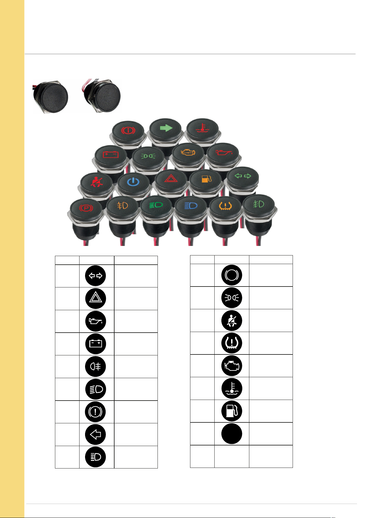
Custom options
Secret Until Lit Polycarbonate Inserts
Off
Suffix the part number with legend code (see example on page 5)
Code Symbol Description
-3AH Turn Signal
-313 Hazard
-3GP Oil can
-3AG Battery
-327 Rear fog
-397 Low beam
-3BU Brake test
Code Symbol Description
-3PB Park Brake
-398 Side Lights
-3SB Seat Belt
-3TP
-3CE
-3EC
-3FP Fuel
Tyre
Pressure
Check
Engine
Engine
Temperature
APEM
-3K6 Arrow
-3AJ High beam
Some common codes are listed above, for your custom requirements please contact APEM.
www.apem.com
-3BF Brake Failure
3
Page 4
Q SERIES Ø16mm (.630") Panel Mount LED Indicators
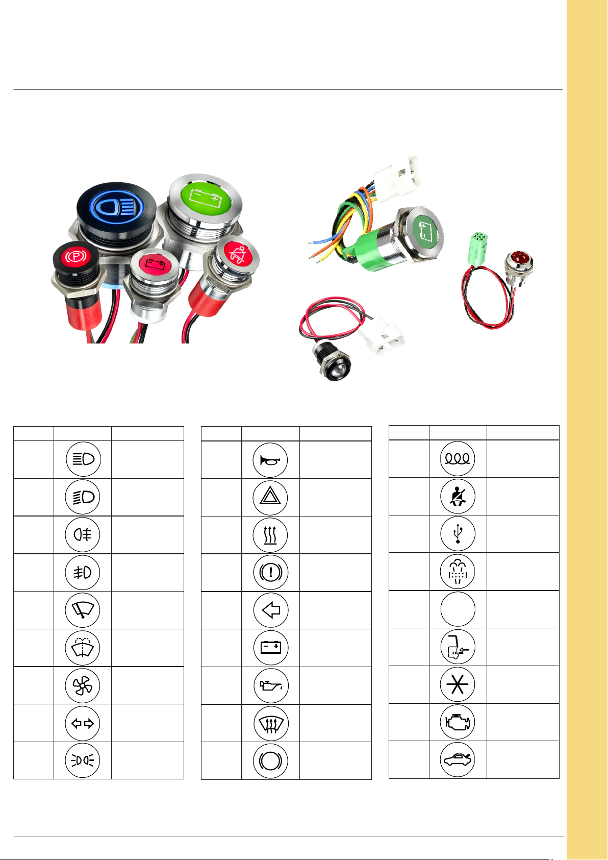
Custom options
Custom Engraving
Cable length & connector
For custom cable length and
connectors please contact
APEM
Suffix the part number with legend code (see example on page 5)
Code Symbol Description
-0AJ High Beam
-097 Low Beam
-027 Rear Fog
-026 Front Fog
-021
-022
-023
Windscreen
Wiper
Windscreen
Washer
Ventilator
Fan
Code Symbol Description
-041 Horn
-013
-018 Heating
-0BU Brake Test
-0K6 Arrow
-0AG Battery
-0GP Oil Can
Hazard
Warning
Code Symbol Description
-0EL
-0SB Seat Belt
-0UB
-0ST Steam
-0EU ECU
-0AD Side Step
-012 Air Con
Engine
Coil
USB
Connection
-0AH
-098 Side Lights
Some common codes are listed above, for your custom requirements please contact APEM.
Unless specified standard engraving with white infill will be supplied.
4
Turn
Signal
-020
-086 ABS
www.apem.com
Windscreen
Heating
-040 Engine
-0BR
Boot/Trunk
Release
APEM
Page 5
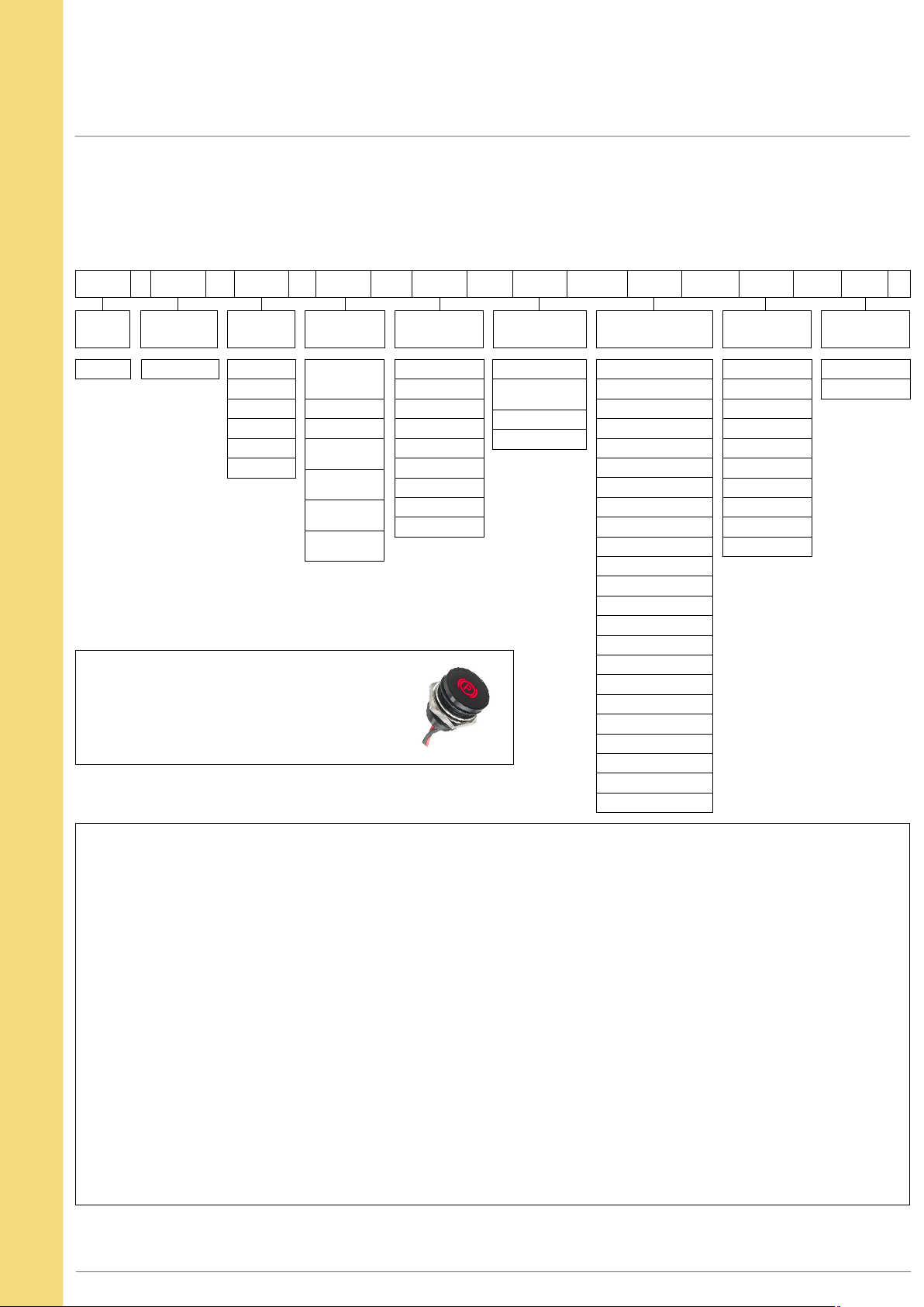
Q SERIES Ø16mm (.630") Panel Mount LED Indicators
Overview
STANDARD OPTIONS
The Q16 Series is available with a range of standard options, to specify your LED, simply choose one option from each
column. An example is shown below.
Q 16 F 1 G XX Y 24 E
SERIES
Q
MOUNTING
HOLE
16 = Ø16mm
BEZEL
STYLE
Metal
P = Prominent
F = Flush
Plastic
PP = Prominent
FP = Flush
TERMINALS BEZEL FINISH
1 = Solder Lug/
Fastons
(2.8 x 0.8)
2 = Pins
3 = Wires
4 = Rear epoxy
Pins
5 = Rear epoxy
Wires
6 = Short body
Pins
7 = Short body
Wires
Example Q16F7BXXHR12E-3PB
Ø16mm, flush metal bezel, wire terminals
Matt black chrome finish, fixed light,
Red, 12VDC LED, IP67 panel sealed
Secret until lit Park Brake Symbol (see page 3)
Metal
C = Bright Chrome
B = Black Chrome
G = Satin Grey
Plastic
CP = Bright
BP = Black
GP = Satin Grey
AU = Gold
TYPE OF
ILLUMINATION
XX = Fixed Light
KK = Flashing Light
(12 - 28VDC)
YY = Bi-color
ZZ = Tri-color
LED COLOR VOLTAGE SEALING
R = Red
G = Green
Y = Yellow
B = Blue
W = White
O = Orange
HR = Hyper Bright Red
HG = Hyper Bright Green
HY = Hyper Bright Yellow
HO = Hyper Bright Orange
SR = Super Bright Red
SG = Super Bright Green
SY = Super Bright Yellow
SB = Super Bright Blue
SW = Super Bright White
RG = Red/Green
RY = Red/Yellow
GY = Green/Yellow
02 = no resistor*
06 = 6VDC
12 = 12VDC
12A = 12VAC/DC
24 = 24VDC
24A = 24VAC/DC
28 = 28VDC
28A = 28VAC/DC
110 = 110VAC
220 = 220VAC
(Blank) = Unsealed
E = IP67
RYG = Red/Yellow/Green
• Gold Faston terminal denotes Anode (+), silver terminal denotes Cathode (-)
• Standard wire length is 200mm, 22AWG UL1007, red wire denotes Anode (+), black wire denotes Cathode (-)
for other wire lengths consult APEM
• For LEDs with alternative voltages consult APEM
• Bi-color LEDs, by connecting the gold Faston (+) one color is produced,
by reversing the supply voltage another color is produced – Bi-colors are available up to 28VDC
• Take care when soldering to the Faston terminals (recommended solder temperature 300°C - 3 sec)
• Short body pins and wires are only available up to 28VDC
• The Tri-color LED has red and green LEDs when both are connected yellow is produced
• Standard Tri-color Faston terminals are two Anodes (+) and one Cathode (-)
• Tri-color wires are one red (+) and one green (+) Anode and one black (-) Cathode
• Tri-color pins are center (–) Cathode, shortest (+) Anode pin green, longest (+) Anode pin red
• Maximum panel thickness 11mm
• We recommend using Hyperbright or Superbright LEDs for use at 110VAC and 220VAC
For multi-voltage options please consult APEM
•
* = For resistorless versions (02) please refer to the forward voltage on page 1
APEM
www.apem.com
5
 Loading...