

Page 1
APEM www.apem.com G-3
G
A1-A01-A02-A03 series
Industrial controls
Distinctive features
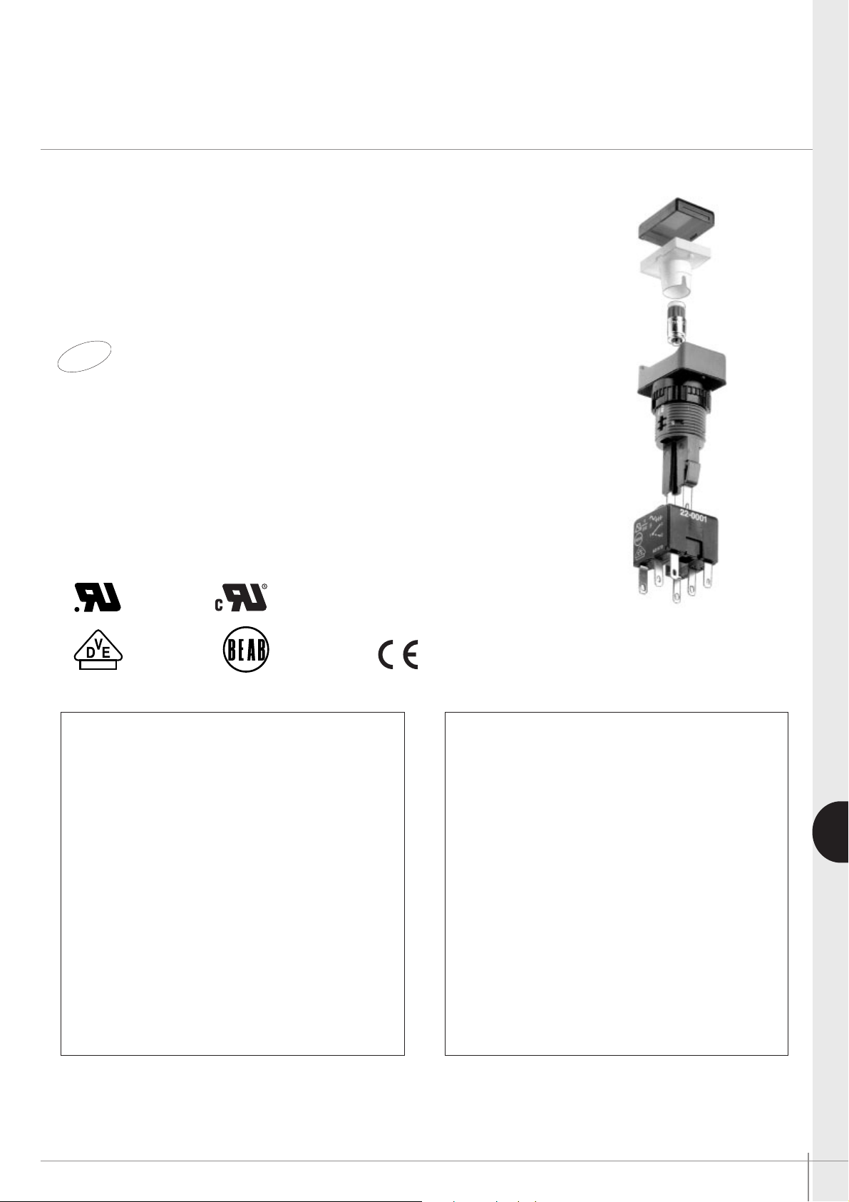
The A01 and A02 series offer ranges of :
- pushbutton switches, illuminated or not
- indicators
- 2 or 3 position keylock switches
- 2 or 3 position rotary lever switches
- emergency stop switches
with rectangular, square or round operators.
• Custom engraved aluminium pushbutton switches, A1 series
• Switch enclosures
• Pushbutton switches and indicators, A03 series
❑ Environmental protection : IP65
❑ Modular construction
❑ Electrical life : 50.000 cycles min.
❑ Screen engraving or insertable legends on request
❑ Approvals
UL 1054 BS RIA 20 Shock & Vibration
EN 61058-1 EN 61058-1
pending
A01 - A1 - A03 series
• Panel cut-out :
Ø 16 mm (.630), except :
- flush mount round : Ø 22 mm (.866)
- flush mount rectangular : 20.60 x 26.70 mm
- flush mount square : 20.60 x 20.60 mm
- A1 series : Ø 22 mm (.866)
- A03 series : round or square Ø 22 (.866)
flush mount : Ø 30 mm (1.378)
• 1, 2, 3 and 4 poles
• Solder lug/quick-connect terminals
• Contacts : silver, gold plated
• Current/voltage rating :
6A 250VAC max. - 10mA 5VAC min.
• Lamp : filament, neon or LED
A02 series
• Panel cut-out :
- round or square : Ø 22 mm (.866)
- rectangular : 29,5 x 21,5 mm (1.160x.846)
- flush mount : Ø 30 mm (1.378)
• 1 and 2 poles
• Screw terminals (optional : quick-connect term.)
• Contacts : silver
• Current/voltage rating : 12A 380VAC
16A 250VAC max. - 25mA 5VAC min.
• Lamp : filament, neon, LED
or special multi-LED array
Option : end cap terminal guard. Order separately
(see end of A02 series).
Each sub-assembly has
to be ordered separately.
Packaging unit :
A1 : 25 pieces - A01 : 20 pieces (except pushbuttons: 25 pieces) - A02 : 25 pieces - A03 : 10 pieces.
Dimensions : first dimensions are in mm while inches are shown as bracketted numbers.
New!
Page 2
G-4 APEM www.apem.com
A1-A01-A02-A03 series
Industrial controls
Specifications for pushbutton, keylock and rotary switches
G
ELECTRICAL SPECIFICATIONS
A01 - A1 - A03 A02
• Function :
Momentary Momentary
or maintained action or maintained action
• Current/voltage rating : 10mA 5VAC min. 25mA 5VAC min.
6A 250VAC max. - 6A 12VDC max.
12A 380VAC - 16A 250VAC max.
12A 12VDC max.
• Contact gap > 1 mm (.039)
Double break 2 x 1,5 mm (.059)
• Initial contact resistance : 10mΩ max. at 1A 4VDC 10mΩ max. at 1A 4VDC
• Insulation resistance : 50 MΩ min. 50 MΩ min.
• Dielectric strength : 750V between open contacts 2KV between open contacts
5KV live to accessible 4KV live to accessible
• Electrical life (resistive load) : 50.000 cycles 50.000 cycles
• Insulation :Class 2 Class 2
• Lamp life :
LED : 60.000 h min. to 75% relative LED : 60.000 h min. to 75 % relative
luminosity - Filament : approx. 5.000 h luminosity - Filament : approx. 5.000 h
Neon : approx. 10.000 h Neon : approx. 10.000 h
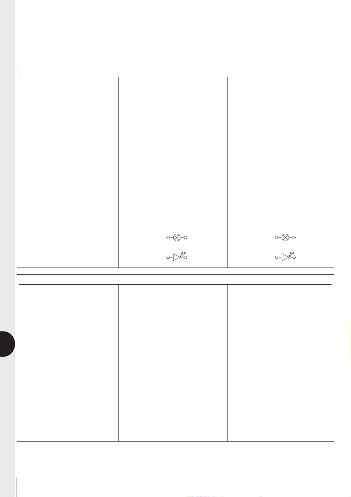
• Lamp circuit diagrams
GENERAL SPECIFICATIONS
A01 - A1 - A03 A02
• Min. mechanical life :
Pushb. momentary : 1 million cycles Pushb. momentary: 1 million cycles
Pushb. maintained : 100.000 cycles Pushb. maintained : 100.000 cycles
Keylock and rotary : 100.000 cycles Keylock and rotary : 100.000 cycles
• Panel thickness 8 mm (.315) max. 8 mm (.315) max.
• Operating temperature : -20°C to +55°C -20°C to +85°C
• Solder heat resistance : 350°C, 5 sec. 350°C, 5 sec.
(IEC 68-2-20Tb, method 2)
• Degree of environmental IP 65 front of panel IP 65 front of panel
protection (IEC 529 ) IP 40 back of panel IP 40 back of panel
• Lamps :Midget Grooved T1
3/4,Midget Grooved T13/4,
filament, LED or neon filament, LED or neon
Special multi-LED array
• Switch terminals :
Solder/quick-connect 2,8 mm (.110) M3 screws - wire 2 x 0,75 mm
2
max.
• Lamp terminals :
Solder/quick-connect 2,8 mm (.110) M3 screws
Flexible wire 2 x 2,5 mm2 max.
Rigid wire 4 mm2 max.
Specifications for emergency stop switches : see pages 10 and 22.
For screen engraving or film legends, contact APEM.
AB
AB
Page 3
APEM www.apem.com G-5
G
A1 series
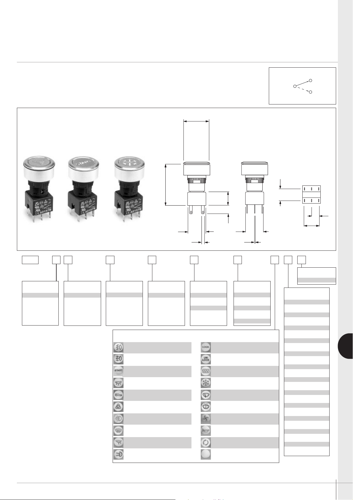
Engraved aluminium flush mounting pushbuttons and indicators
Panel cut-out Ø 22 (.866)
A pushbutton assembly requires :
engraved screen + lamp (if illuminated) + operator + switch block + flush mount bezel.
To order these elements, select desired model numbers from the table below.
Example : pushbutton, round, illuminated, sealed to IP65, latching, single pole with “start”
engraving, 24V blue LED and flush mounting bezel = A1PCA1X103K403.
01 - Front Fog Lights
02 - Rear Fog Lights
03 - ‘Start’
04 - Interior Light
05 - Boot Release
06 - Hazard Warning
07 - Lights
08 - Heating & Ventilation
09 - Map Lights
10 - Side Lights
11 - ‘Lock’
12 - ‘Unlock’
13 - Rear Window Heating
14 - Cooling
15 - Wipers
16 - Washers
17 - Fan
18 - Horn
19 - Air recirculation
20 - Blank
Engraved Screen Options
A1
Switch Type
P - pushbutton
I - indicator
Accessories
03 - flushmount
Bezel
C - round
Illumination
A - illuminated
B - non-illum.
Sealing
0 - unsealed
1 - sealed IP65
Function
0 - indicator
X - latching
Y - momentary
Switch block
0 - indicator
1 - single pole
2 - double pole
5 - three pole
3 - four pole
Bulb
A1 - filament 6.3V
B1 - filament 14V
C1 - filament 28V
D1 - filament 36V
E1 - filament 48V
F1 - filament 60V
G1 - Neon 110V
H1 - Neon 220V
I1 - Led 6V red
I2 - Led 6V green
I3 - Led 6V amber
J1 - Led 12V red
J2 - Led 12V green
J3 - Led 12V amber
J4 - Led 12V blue
J5 - Led 12V white
K1 - Led 24V red
K2 - Led 24V green
K3 - Led 24V amber
K4 - Led 24V blue
K5 - Led 24V white
L1 - Led 48V red
L2 - Led 48V green
L3 - Led 48V amber
OTHER SCREEN ENGRAVING OPTIONS :
contact APEM.
Ø25.00
(9.85 DIA)
42.05
(1.655)
14.5
(.571)
8.5
(.335)
18.00
(.709)
2.8
(.110)
18.00
(.709)
1
12.00
(.472)
0.5
(.020)
15.3
(.602)
3
2
7.65
(.301)
Page 4
G-6 APEM www.apem.com
A01 series
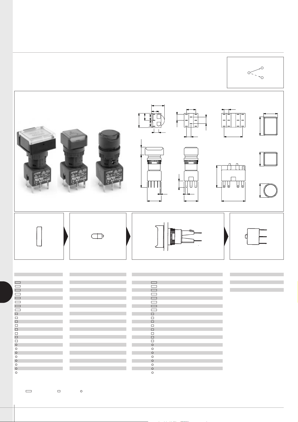
Illuminated or non-illuminated pushbutton switches
Panel cut-out Ø 16 (.630)
G
)456.1( )493.(
(.020)
(.709)
(.110)
(.709)
)103.(
)549.(
)QS 907.()AID 907.(
(.709)
(.236)
(.472)
)533.(
00.0100.24
56.
7
05.8
00.81x00.8100.42Ø00.81
12.00
6.00
18.00
0.50
18.00
2.80
18.00
)033.(
04.
8
(1.209)
)2
2
1.1(
(.945)
(.236)
05
.
8
2
6.00
24.00
30.70
12 3
321
3
2
1
12 3
321
12 3
CD EFC D
)103.(
56.
7
)103.(
56.
7
(.236)
6.00
)907.(
00.81
16.25
(.640)
9.00
(.354)
9.00
(.354)
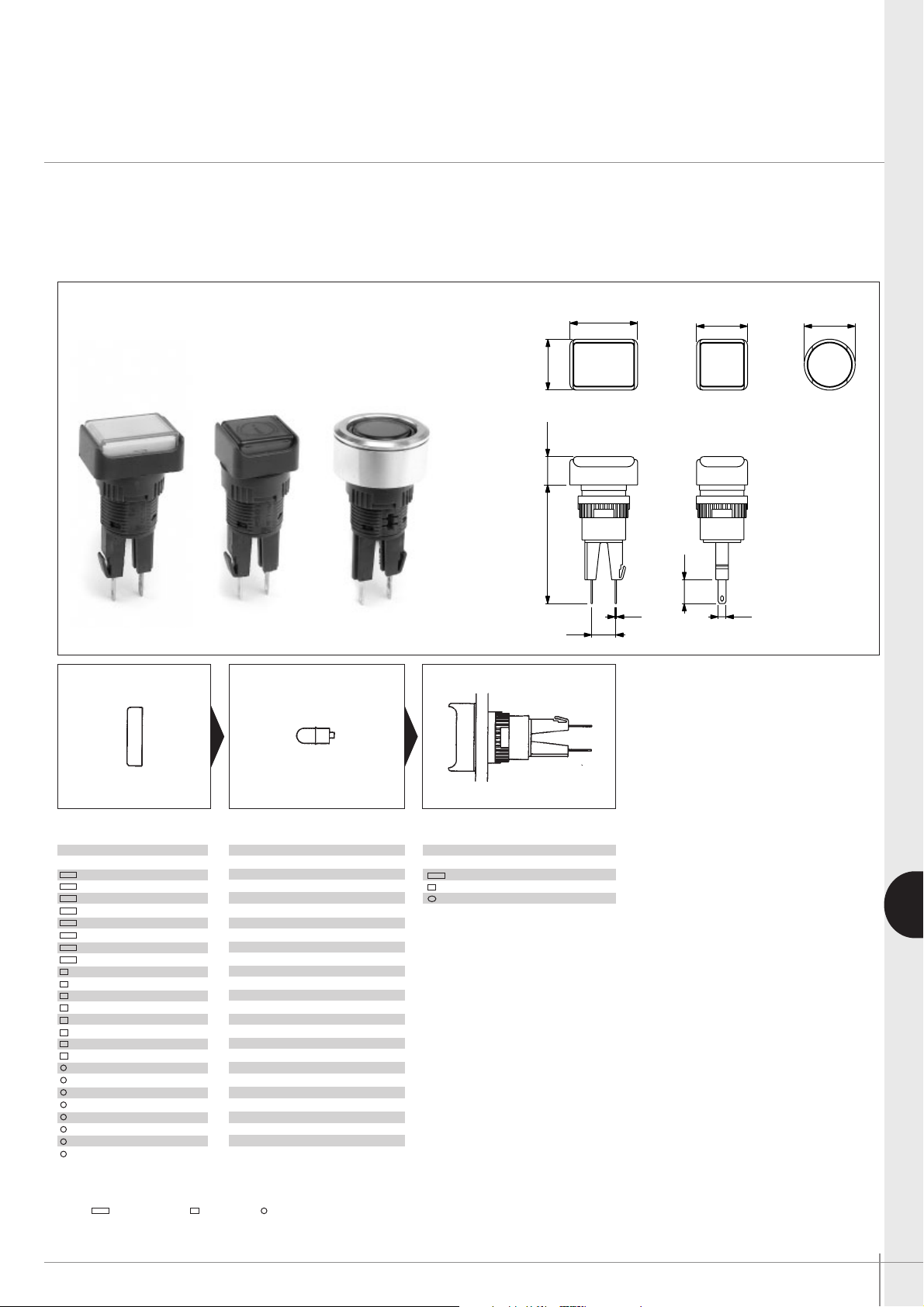
A pushbutton assembly requires :
screen + lamp (if illuminated) + operator + switch block.
To order these elements, select desired model numbers from tables below.
Example : IP65 rectangular pushbutton, single pole, maintained, red screen and 12V red LED =
A0161B, A0142M1, A0101X and A0151BUL.
Screen Lamp Operator Switch block
SCREEN ENGRAVING/INSERTABLE LEGENDS : contact APEM
Bezel: rectangular, square, round, ‘Illum’ - illuminated, ‘Non-illum’ - non illuminated
❶
❷
❸❹
UNSEALED SWITCHES (IP40) :
add “01” to end of operator
model number.
BI-COLOUR LED’s optional.
Bezel Colour Part No
black A0161A
red A0161B
amber A0161C
yellow A0161D
green A0161E
blue A0161F
clear A0161G
white A0161J
black A0162A
red A0162B
amber A0162C
yellow A0162D
green A0162E
blue A0162F
clear A0162G
white A0162J
black A0163A
red A0163B
amber A0163C
yellow A0163D
green A0163E
blue A0163F
clear A0163G
white A0163J
Pole Bezel Description Part No
1 or 2 Illum, momentary A0101Y
1 or 2 Illum, maintained A0101X
1 or 2 Non-illum, momentary A0102Y
1 or 2 Non-illum, maintained A0102X
3 or 4 Illum, momentary A0103Y
3 or 4 Illum, maintained A0103X
3 or 4 Non-illum, momentary A0104Y
3 or 4 Non-illum, maintained A0104X
1 or 2 Illum, momentary A0105Y
1 or 2 Illum, maintained A0105X
1 or 2 Non-illum, momentary A0106Y
1 or 2 Non-illum, maintained A0106X
3 or 4 Illum, momentary A0107Y
3 or 4 Illum, maintained A0107X
3 or 4 Non-illum, momentary A0108Y
3 or 4 Non-illum, maintained A0108X
1 or 2 Illum, momentary A0109Y
1 or 2 Illum, maintained A0109X
1 or 2 Non-illum, momentary A0110Y
1 or 2 Non-illum, maintained A0110X
3 or 4 Illum, momentary A0111Y
3 or 4 Illum, maintained A0111X
3 or 4 Non-illum, momentary A0112Y
3 or 4 Non-illum, maintained A0112X
Lamp Voltage Part No
Filament 6.3V A0141A
Filament 14V A0141B
Filament 28V A0141C
Filament 36V A0141D
Filament 48V A0141E
Filament 60V A0141F
Neon 110V A0143G
Neon 220V A0143H
LED 6V red A0142L1
LED 6V green A0142L2
LED 6V amber A0142L3
LED 12V red A0142M1
LED 12V green A0142M2
LED 12V amber A0142M3
LED 12V blue A0142M4
LED 12V white A0142M5
LED 24V red A0142N1
LED 24V green A0142N2
LED 24V amber A0142N3
LED 24V blue A0142N4
ED 24V white A0142N5
LED 48V red A0142P1
LED 48V green A0142P2
LED 48V amber A0142P3
No of poles Part No
Single pole A0151BUL
Double pole A0152BUL
Three pole A0155BUL
Four pole A0153BUL
3
1
2
Page 5
APEM www.apem.com G-7
G
A01 series
Indicators
Panel cut-out Ø 16 (.630)
An indicator assembly requires :
screen + lamp + operator.
To order these elements, select desired model numbers from tables below.
Example : IP65 rectangular indicator with red screen and 12V red LED = A0161B, A0142M1
and
A0171.
(.945)
(.709) (.709 DIA)
(.709)
18.00
24.00
Ø18.00
18.00
(1.654) (.394)
(.020) (.110)
(.335)
(.330)
10.0042.00
8.40
0.50
8.50
2.80
Screen Lamp
Operator
SCREEN ENGRAVING / INSERTABLE LEGENDS : contact APEM
Bezel: rectangular, square, round
❶
❷
❸
UNSEALED INDICATORS (IP40) :
add “01” to end of operator model
number.
Bezel Colour Part No
black A0161A
red A0161B
amber A0161C
yellow A0161D
green A0161E
blue A0161F
clear A0161G
white A0161J
black A0162A
red A0162B
amber A0162C
yellow A0162D
green A0162E
blue A0162F
clear A0162G
white A0162J
black A0163A
red A0163B
amber A0163C
yellow A0163D
green A0163E
blue A0163F
clear A0163G
white A0163J
Bezel Description Part No
Indicator A0171
Indicator A0172
Indicator A0173
Lamp Voltage Part No
Filament 6.3V A0141A
Filament 14V A0141B
Filament 28V A0141C
Filament 36V A0141D
Filament 48V A0141E
Filament 60V A0141F
Neon 110V A0143G
Neon 220V A0143H
LED 6V red A0142L1
LED 6V green A0142L2
LED 6V amber A0142L3
LED 12V red A0142M1
LED 12V green A0142M2
LED 12V amber A0142M3
LED 12V blue A0142M4
LED 12V white A0142M5
LED 24V red A0142N1
LED 24V green A0142N2
LED 24V amber A0142N3
LED 24V blue A0142N4
LED 24V white A0142N5
LED 48V red A0142P1
LED 48V green A0142P2
LED 48V amber A0142P3
Page 6
G-8 APEM www.apem.com
A01 series
Rotary lever switches
Panel cut-out Ø 16 (.630)
G
(1.654) (.394)
(.020)
(.709)
(.110)
(.709)
(.301)
(.945)
(.709 SQ)
(.709 DIA)
(.709)
(1.209)
(1.122)
(.945)
(.236)
(.472)
10.0042.00
7.65
28.50
18.00x18.00
24.00
Ø18.00
12.00
6.00
18.00
24.00
0.50
18.00
2.80
18.00 30.70
(.330)
8.40
CD
12 3
321
321
12 3
321
12 3
CD EF
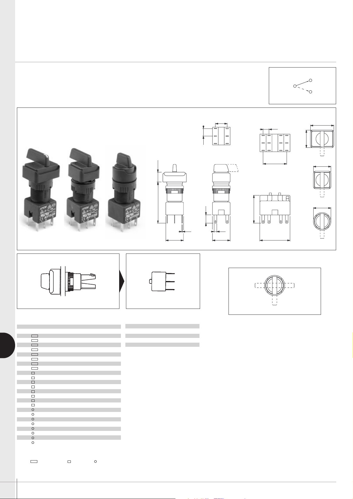
A rotary lever switch assembly requires :
operator + switch block.
To order these elements, select desired model numbers from tables below.
Example : IP65 rectangular rotary switch with long lever, clockwise rotation, single pole,
2 positions, maintained
= A019109 and A0151BUL.
• Lever Rotation - 2 position switches
The model numbers shown are for switches
with clockwise lever rotation.
For anticlockwise rotation, replace :
09 with 01
10 with 02
11 with 03
12 with 04
at the end of the model number.
Lever Positions
Operator Switch block
Bezel: rectangular, square, round, ‘pos’ - position, ‘mainL’ - maintained left, ‘momR’ - momentary right, etc
❶
❷
See above photo left.
To order, add “WL” to the end of the operator
part No.
Example : A019609WL..
Optional Engraving on
Lever end
Pole Bezel Description Short lever Long lever
1 or 2 2 pos. maintained A019209 A019109•
1 or 2 2 pos. momentary A019210 A019110•
3 or 4 2 pos. maintained A019211 A019111•
3 or 4 2 pos. momentary A019212 A019112•
1 or 2 3 pos. maintained A019205 A019105
1 or 2 3 pos. momentary A019206 A019106
1 or 2 3 pos. mainL, momR A019207 A019107
1 or 2 3 pos. momL, mainR A019208 A019108
1 or 2 2 pos. maintained A019409 A019309•
1 or 2 2 pos. momentary A019410 A019310•
3 or 4 2 pos. maintained A019411 A019311•
3 or 4 2 pos. momentary A019412 A019312•
1 or 2 3 pos. maintained A019405 A019305
1 or 2 3 pos. momentary A019406 A019306
1 or 2 3 pos. mainL, momR A019407 A019307
1 or 2 3 pos. momL, mainR A019408 A019308
1 or 2 2 pos. maintained A019609 A019509•
1 or 2 2 pos. momentary A019610 A019510•
3 or 4 2 pos. maintained A019611 A019511•
3 or 4 2 pos. momentary A019612 A019512•
1 or 2 3 pos. maintained A019605 A019505
1 or 2 3 pos. momentary A019606 A019506
1 or 2 3 pos. mainL, momR A019607 A019507
1 or 2 3 pos. momL, mainR A019608 A019508
No of poles Part No
Single pole A0151BUL
Double pole A0152BUL
Three pole A0155BUL
Four pole A0153BUL
3
1
2
CB
A
Page 7
APEM www.apem.com G-9
G
A01 series
Keylock switches
Panel cut-out Ø 16 (.630)
Bezel: rectangular, square, round, ‘pos’ - position, ‘mainL’ - maintained left, ‘momR’ - momentary right, etc
(1.654) (1.496)
(.020)
(.709)
(.110)
(.709)
(.301)
(.945)
(.709 SQ)
(.709 DIA)
(.709)
(.945)
(.236)
(.472)
38.0042.00
7.65
18.00x18.00
24.00
Ø18.00
12.00
6.00
18.00
24.00
0.50
18.00
2.80
18.00
(.330)
8.40
(1.209)
(1.122)
28.50
30.70
CD
12 3
321
321
12 3
321
12 3
CD EF
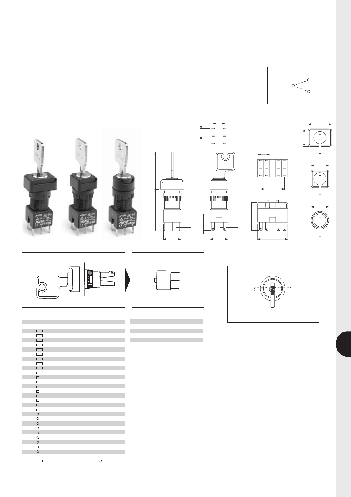
A keylock switch assembly requires :
operator + switch block.
To order these elements, select desired model numbers from tables below.
Example : IP65 rectangular keyswitch, clockwise rotation, single pole, 2 positions, maintained
= A018125 and A0151BUL
.
• Key Rotation - 2 position switches
The model numbers shown are for switches
with clockwise key rotation.
For anticlockwise rotation, replace :
25 with 01
24 with 02
27 with 03
28 with 04
at the end of the model number.
2 standard keys are supplied.
20 key barrel types available from stock.
Operator Switch block
Key Positions
❶
❷
NON-REMOVABLE KEY POSITIONS / ON-ON-ON FUNCTION : contact APEM.
Pole Bezel Description Part No Key removable
1 or 2 2 pos. maintained A018123 A
1 or 2 2 pos. maintained A018125• A-B
1 or 2 2 pos. momentary A018124• A
3 or 4 2 pos. maintained A018127• A-B
3 or 4 2 pos. momentary A018128• A
1 or 2 3 pos. maintained A018105 A-B-C
1 or 2 3 pos. momentary A018106 A
1 or 2 3 pos. mainL, momR A018107 A-B
1 or 2 3 pos. momL, mainR A018108 A-C
1 or 2 2 pos. maintained A018223 A
1 or 2 2 pos. maintained A018225• A-B
1 or 2 2 pos. momentary A018224• A
3 or 4 2 pos. maintained A018227• A-B
3 or 4 2 pos. momentary A018228• A
1 or 2 3 pos. maintained A018205 A-B-C
1 or 2 3 pos. momentary A018206 A
1 or 2 3 pos. mainL, momR A018207 A-B
1 or 2 3 pos. momL, mainR A018208 A-C
1 or 2 2 pos. maintained A018323 A
1 or 2 2 pos. maintained A018325• A-B
1 or 2 2 pos. momentary A018324• A
3 or 4 2 pos. maintained A018327• A-B
3 or 4 2 pos. momentary A018328• A
1 or 2 3 pos. maintained A018305 A-B-C
1 or 2 3 pos. momentary A018306 A
1 or 2 3 pos. mainL, momR A018307 A-B
1 or 2 3 pos. momL, mainR A018308 A-C
No of poles Part No
Single pole A0151BUL
Double pole A0152BUL
Three pole A0155BUL
Four pole A0153BUL
3
1
2
B
C
A
Page 8
G-10 APEM www.apem.com
A01 series
Emergency stop switches
Panel cut-out Ø 16 (.630)
G
60 mm Ø Self
Adhesive Label
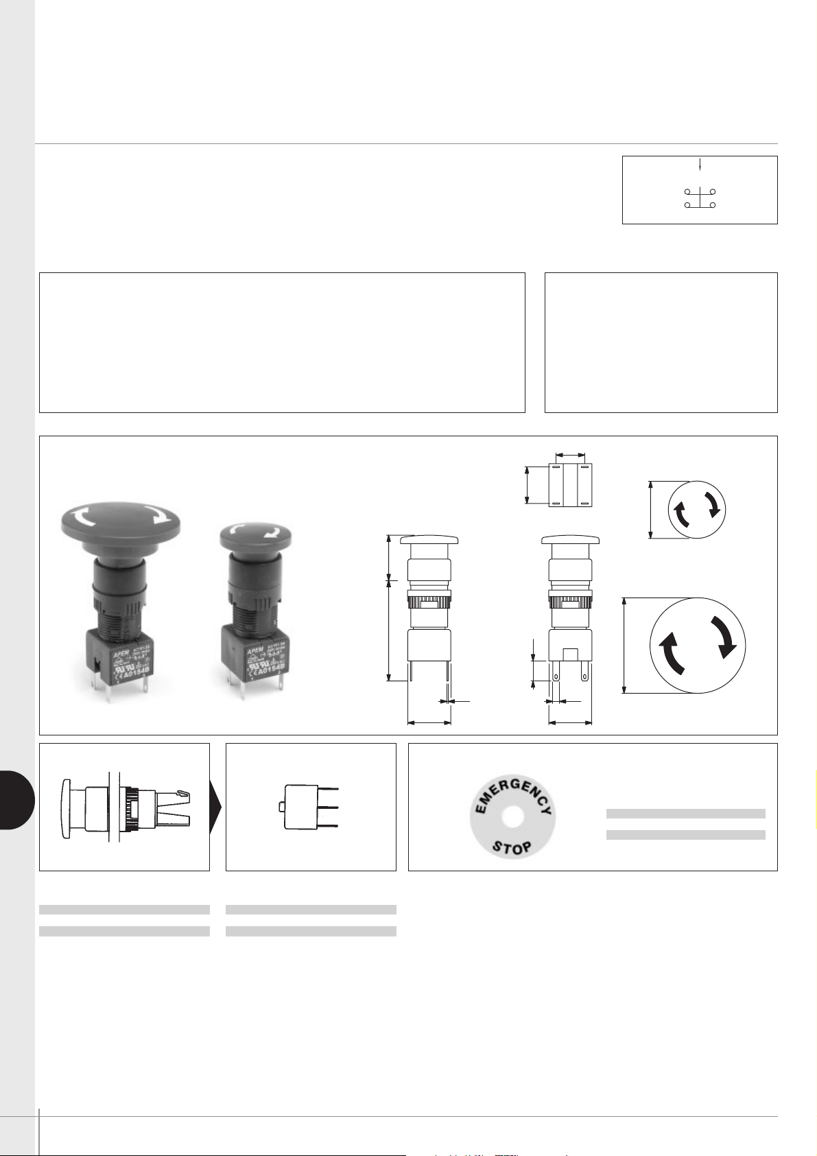
• Prominent 24 mm (.944) dia. or optional 40 mm (1.575) dia. red mushroom actuator
• Highly reliable positive break switch
• Push to shut off switch, twist to reset to ON
• Approved to UL 1054 / EN 60947-5-1
An emergency stop switch assembly requires : operator + switch block.
To order, specify with single pole or double pole positive break switch block.
Operator Switch block
Accessory
❶
❷
General specifications
• Min. mechanical life : 6.050 cycles (6 cycles per minute)
• Operating force / torque : 16 N / 0,1 Nm
• Operating temperature : -20°C to +55°C
• Solder heat resistance : 350°C, 5 secs (IEC 68-2-2-20Tb, method 2)
• Degree of environmental protection (IEC 529) :
IP65 front of panel, IP40 back of panel
• Switch terminals : solder/quick-connect 2,8 mm (.110) (IEC 68-2-20)
Electrical specifications
• Current/voltage rating :
1,5A 250VAC AC-15
• Contact gap : > 3 mm (.118)
• Dielectric strength : 2.900V
• Electrical life : 6.050 cycles
Option : SP3 version
No of poles Part No
Single pole A0150BUL
Double pole A0154BUL
Description Part No
24 mm Ø Emergency stop A01ES
40 mm Ø Emergency stop A01ES SP3
Description Part No
Yellow label with text A01YL1
Yellow label A01YL2
N.C.
19.0042.00
(1.654) (1.047)
12.00
(.472)
15.30
(.602)
Ø24.00
(.945 DIA)
8.40
(.330)
CD
Ø40.00
18.00
(.709)
0.50
(.020)
2.80
(.110)
18.00
(.709)
Page 9
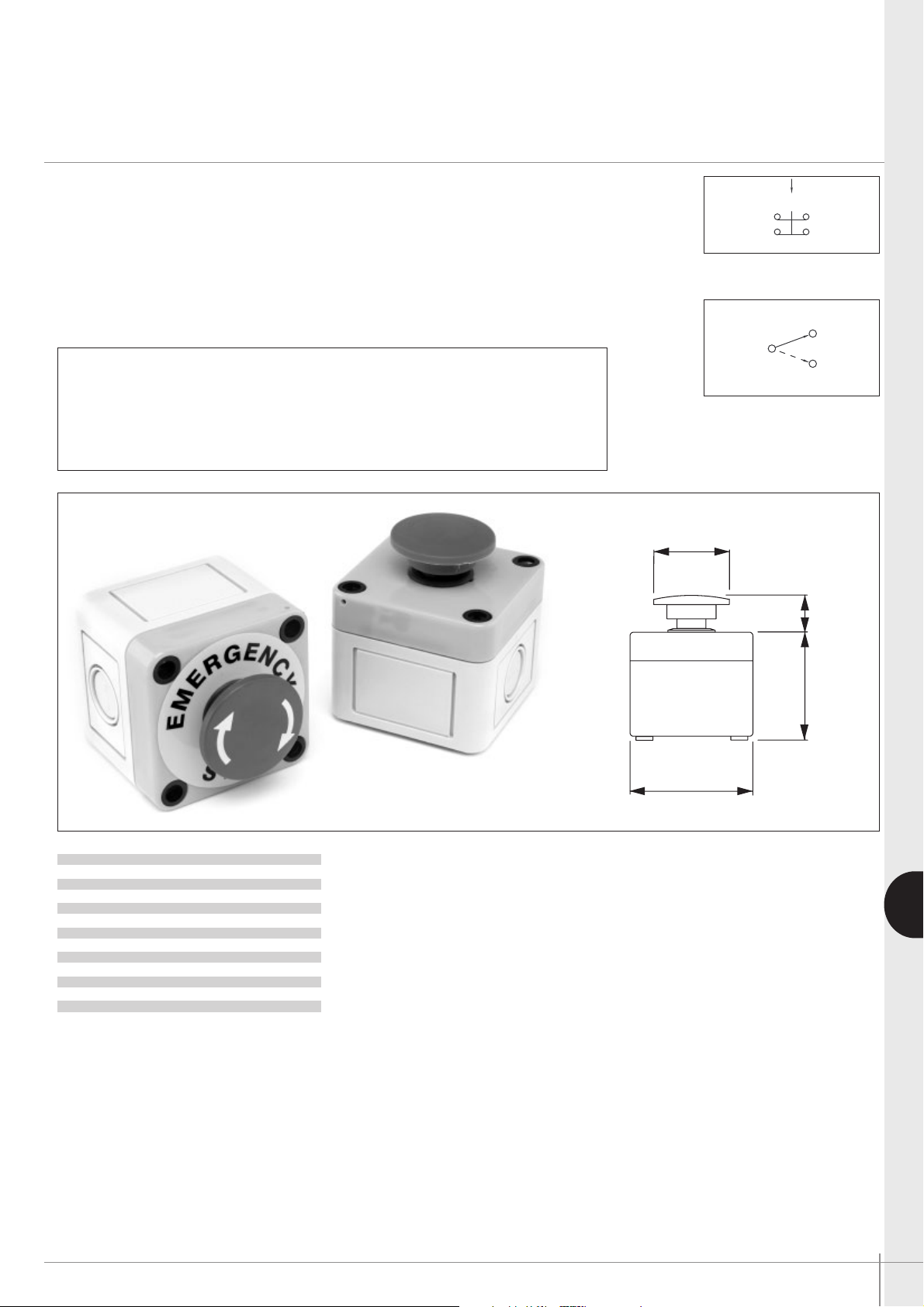
APEM www.apem.com G-11
G
A01 series
Emergency stop switches/mushroom head pushbutton switches
Fitted in enclosures
• Prominent 40 mm (1.575) dia. mushroom actuator, twist to release
• Highly reliable positive break switching on E-Stop
• Sealed to IP65
• 6A current rating
• Robust polycarbonate enclosures
• Knockouts for popular conduit sizes
• Double pole changeover switch blocks available for momentary/maintained
mushroom head pushbuttons.
Technical specifications
• Contact rating : Pushbutton switch : 6A 250VAC - E-Stop : 1,5A 250VAC
• Dimensions : 65 x 65 x 57 mm
• Electrical life : Pushbutton switch : 50 000 cycles - E-Stop : 6 050 cycles
• Operating temperature : -20°C to +55°C
Emergency stop
Momentary & maintained
OPTIONS
12A 250V versions or custom printing on mushroom head actuators : contact APEM.
Description Part No
Emergency stop A01ESSP354B + PEA01
Black momentary A01MMASP352B + PEA01
Red momentary A01MMBSP352B + PEA01
Yellow momentary A01MMDSP352B + PEA01
Green momentary A01MMESP352B + PEA01
Blue momentary A01MMFSP352B + PEA01
Black maintained A01MXASP352B + PEA01
Red maintained A01MXBSP352B + PEA01
Yellow maintained A01MXDSP352B + PEA01
Green maintained A01MXESP352B + PEA01
Blue maintained A01MXFSP352B + PEA01
N.C.
3
1
2
Ø40.0
(1.575 DIA)
65.0 SQUARE
(2.561)
17.5
55.0
(.689)
(2.167)
Page 10
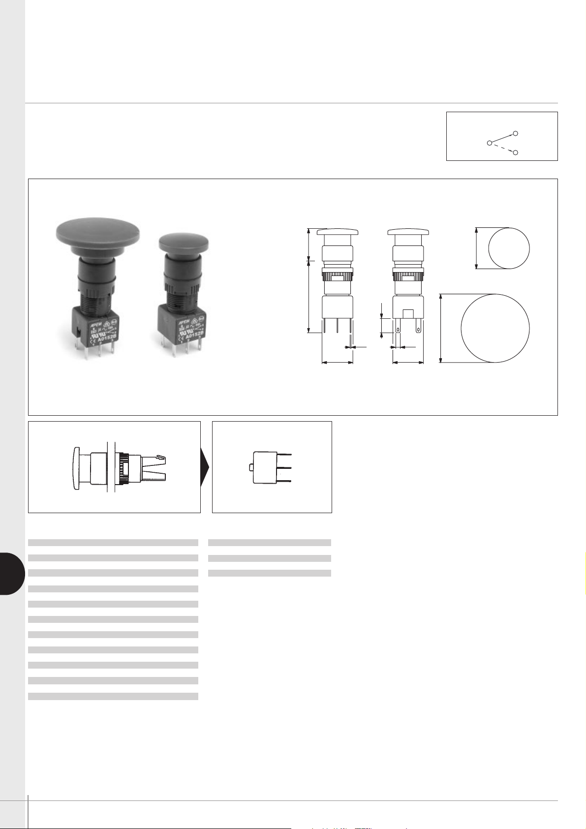
G-12 APEM www.apem.com
A01 series
Mushroom head pushbutton switches
Panel cut-out Ø 16 (.630)
G
• Prominent 24 mm (.944) dia. or optional 40 mm (1.575) dia. mushroom actuators
• Momentary and maintained functions
Momentary function versions are unmarked.
Maintained function versions are twist release (arrows indicate direction of twist)
• Various coloured mushroom actuators are available.
Option : SP3 version
❶
❷
Operator Switch block
No of poles Part No
Single pole A0151BUL
Double pole A0152BUL
Three pole A0155BUL
Four pole A0153BUL
Actuator Description Part No
24mmØ Black momentary A01MMA
24mmØ Red momentary A01MMB
24mmØ Yellow momentary A01MMD
24mmØ Green momentary A01MME
24mmØ Blue momentary A01MMF
24mmØ Black maintained A01MXA
24mmØ Red maintained A01MXB
24mmØ Yellow maintained A01MXD
24mmØ Green maintained A01MXE
24mmØ Blue maintained A01MXF
40mmØ Black momentary A01MMA SP3
40mmØ Red momentary A01MMB SP3
40mmØ Yellow momentary A01MMD SP3
40mmØ Green momentary A01MME SP3
40mmØ Blue momentary A01MMF SP3
40mmØ Black maintained A01MXA SP3
40mmØ Red maintained A01MXB SP3
40mmØ Yellow maintained A01MXD SP3
40mmØ Green maintained A01MXE SP3
40mmØ Blue maintained A01MXF SP3
3
1
2
19.0042.00
(1.654) (1.047)
18.00
(.709)
0.50
(.020)
8.40
(.330)
C D
2.80
(.110)
18.00
(.709)
Ø24.00
(.945DIA)
OPTION : SP3 VERSION
Ø40.00
(1.575 DIA)
Page 11
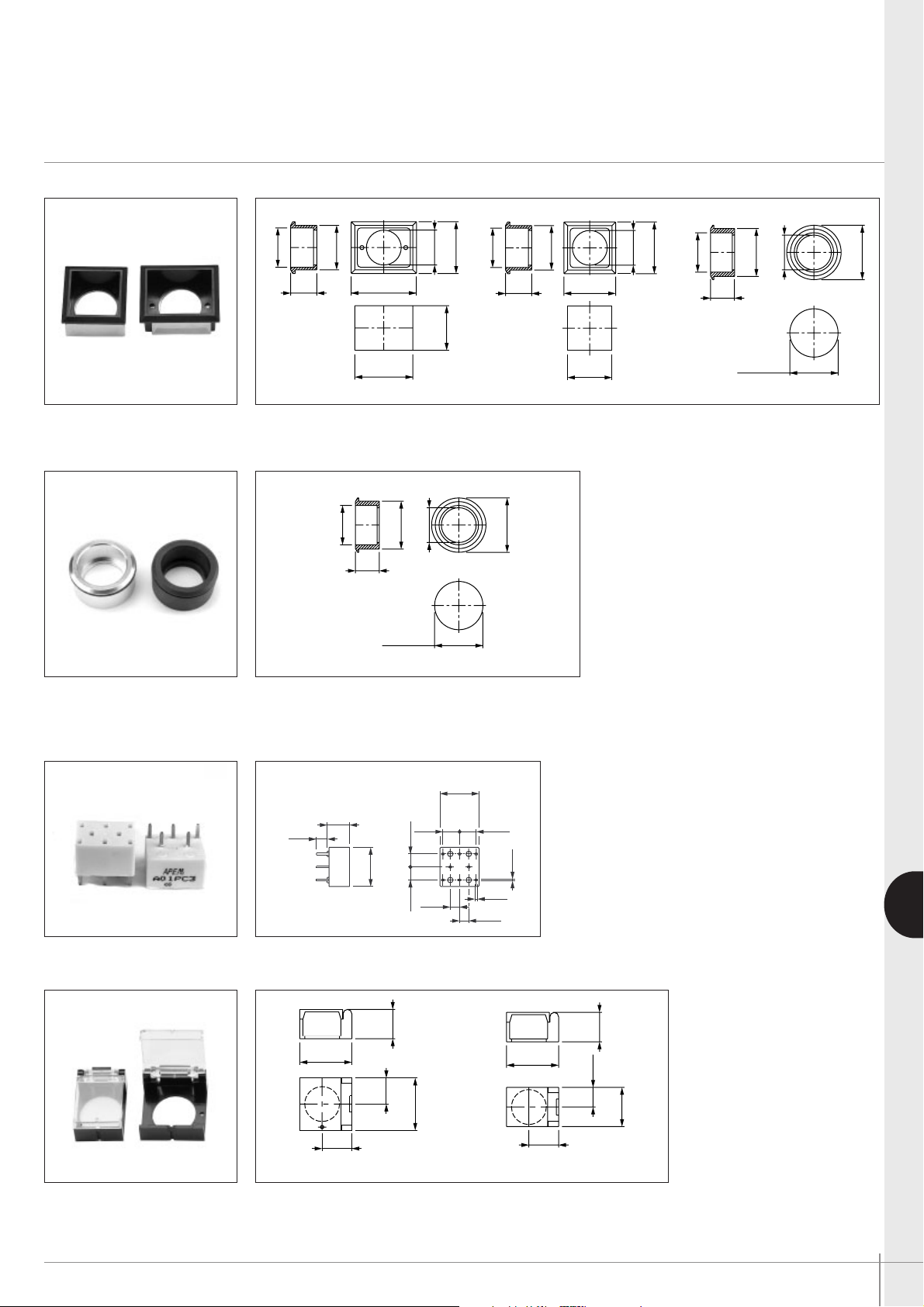
APEM www.apem.com G-13
G
A1-A01 series
Industrial controls
Accessories
FLAPGUARDS
FLUSH MOUNTING BEZELS
Dark grey plastic material - supplied with sealing washer
Rectangular A01FG1
Rectangular A01FM1 Square A01FM Round A01FM2
Square/round A01FG2
(.537)
13.65
24.00
(.945)
12.00
(.472)
13.50
(.531)
24.00
(.945)
(.531)
(.537)
13.65
(.945)
24.00
(.354)
9.00
13.50
(.708)
18.00
12.00
(.472)
20.60
(.811 )
+0.20
0.00
.000
+.008
(1.051 )
26.70
(1.173)
29.80
+0.20
0.00
.000
+.008
20.40
(.712)
18.10
(.803)
(.630DIA)
Ø16.00
23.80
(.937)
FLUSH MOUNTING BEZELS
Metal versions
Round, anodised aluminium A01FMM
Round, matt black A01FMMG
+.008
(.874 )
22.20
11.00
(.433)
(.715)
18.15
(.866 DIA)
Ø22.00
0.00
.000
+0.20
(.630DIA)
Ø16.00
(.984 DIA)
Ø25.00
+.008
(.811 )
.000
20.60
0.00
+0.20
(.472)
12.00
(.937)
23.80
20.40
(.712)
18.10
(.803)
(.937)
23.80
(.630DIA)
Ø16.00
+.008
(.874 )
22.20
11.00
(.433)
(.715)
18.15
(.866 DIA)
Ø22.00
0.00
.000
+0.20
(.630DIA)
Ø16.00
(.984 DIA)
Ø25.00
Single pole, non illuminated A01PC1
Double pole, non illuminated A01PC2
Single pole, illuminated A01PC3
Double pole, illuminated A01PC4
Indicator A01PC5
Single pole, E-stop A01PC6
Double pole, E-stop A01PC7
PCB SOCKET
18.00
(.708)
5.00
(.196)
10.25
(.403)
18.00
(.708)
6.00
6.00
(.236)
(.236)
7.65
(.301)
(.167)
4.25
(.301)
(.043)
4.25
(.167)
7.65
1.10
0.80
(.031)
Page 12
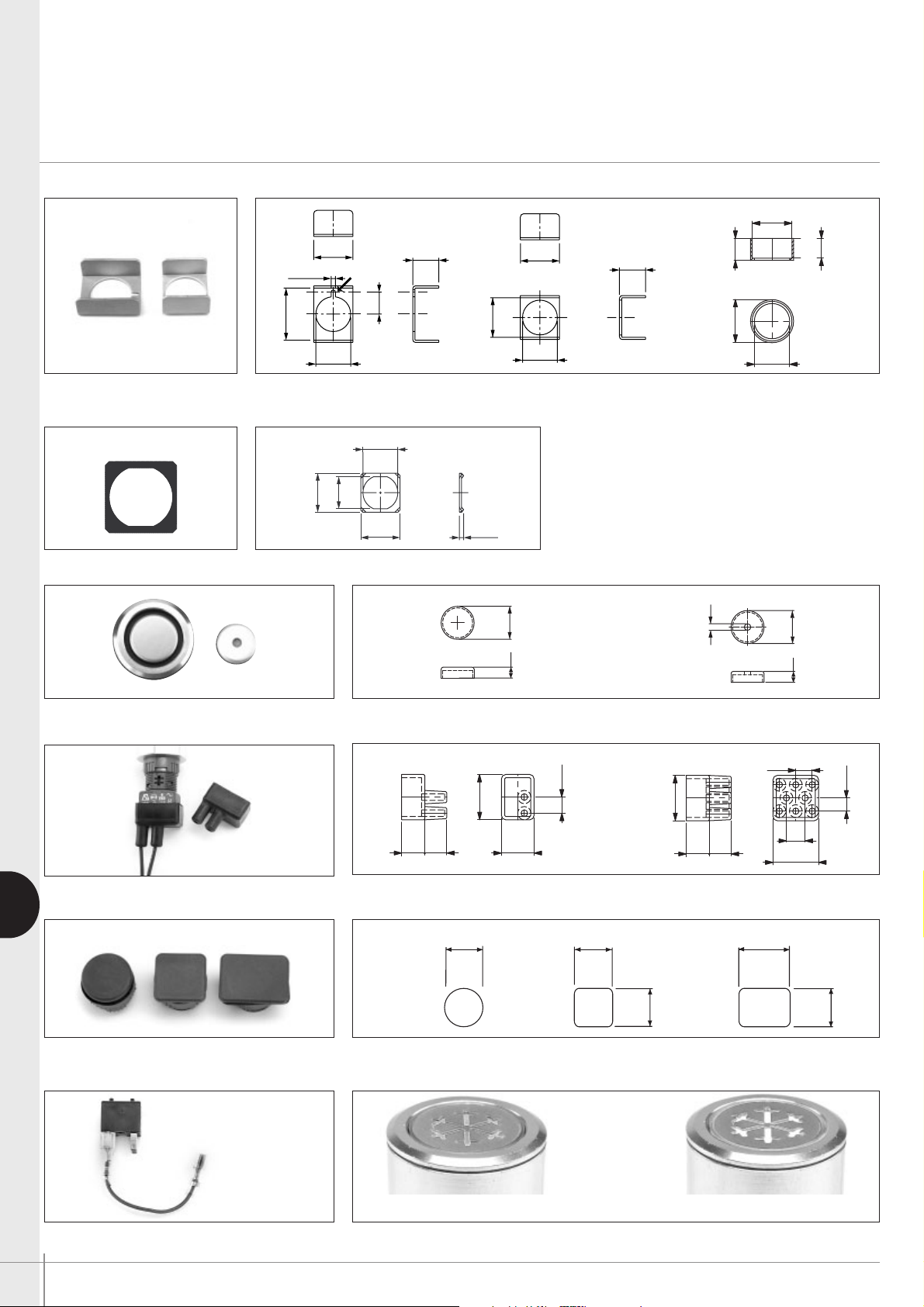
G-14 APEM www.apem.com
A1-A01 series
Industrial controls
Accessories
G
ANTI ROTATION RING
Recommended to prevent product rotation
Resistor assembly - 2 stage illumination
For non-illuminated pushbuttons For illuminated pushbuttons
A01LW
METAL GUARDS
➞
Slot as alternative to Ø 2 mm hole - Material : 1 mm thick aluminium.
Rectangular A01MG1 Square A01MG
Round, natural A01MG2
Matt black A01MG2G
(.630DIA)
Ø16.00
(.944)
24.00
(.399)
10.15
Ø2.00
(.078DIA)
(.708)
18.00
(.472)
12.00
ALUMINIUM SCREENS
A0163AL A0163AL1
00
)
00
)
00
00
)
00
)
SWITCHBLOCK TERMINAL GUARDS
2 way A01RTC2 8 way A01RTC8
18.00
(.717)
18.20
(.630DIA)
Ø16.00
(.708)
12.00
(.472)
Ø16.05
(.631DIA)
(.717)
(.717)
(.771 DIA)
Ø19.60
Ø18.10
(.712 DIA)
18.20
18.20
BLANKING PLUGS
Round A0133 Square A0132 Rectangular A0131
RESISTOR ASSEMBLY
A0152B + RISSP
(DIM) normally closed (BRIGHT) normally open
Ø16.00
(.629DIA)
18.00
(.708)
14.75
(.580)
18.00
(.708)
2.00
(.078)
.
.591 DIA
.
.197
7.35
(.289)
20.75
(.816)
10.50
(.413)
10.00
(.393)
14.85
(.584)
.
7.45
(.293)
20.75
(.816)
10.50
10.00
(.393)(.413)
.
.591 DIA
.
8.50
(.334)
20.75
(.816)
.197
6.00
(.236)
Ø18.0
(.709 DIA)
18.0
(.709)
18.0
(.709)
24.0
(.946)
18.0
(.709)
Page 13
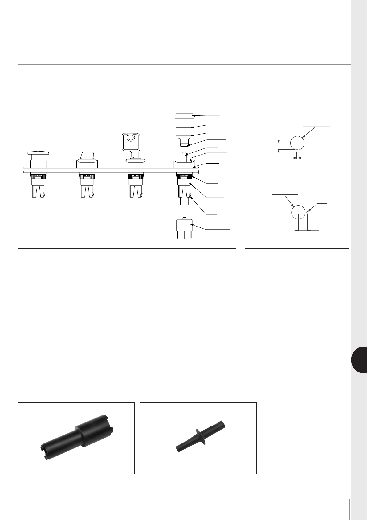
APEM www.apem.com G-15
G
A1-A01 series
Industrial controls
Installation - tools
Modular construction / panel mounting
SWITCH BLOCK
FIXING
NUT
PANEL
BULB
REFLECTOR
LOCATING
SLOT
LEGEND
SCREEN
EMERGENCY
STOP
ROTARY
LEVER SWITCHES
KEYLOCK
SWITCHES
PUSHBUTTONS
& INDICATORS
LATCH
OPERATOR
(.157 MAX)
4.00 Maxi
SEAL
POLARISING
DOT
PANEL CUT-OUT
Round & square operators only
Rectangular operators only
Max. panel thickness : 8 mm (.315)
PANEL MOUNTING ASSEMBLY
• Drill/punch hole shaped as above.
• Assemble front operator through hole, fit fixing nut and
tighten to a maximum torque of 0,8Nm using tool
No 30-0001.
• Wire chosen switch block as required and slide onto
operator until latch engages.
• Fit bulb if required using tool No 30-0002.
• Snap screen onto reflector assembly with legend in
between if required and snap onto front operator TAKING
CARE TO LINE UP THE LOCATING SLOT WITH THE
POLARISING DOT, and not to damage the seal.
TO REMOVE BULB
Remove reflector/screen assembly. Use the bulb extractor
30-0002 to remove the bulb.
SWITCH BLOCK
To assemble switch block to front operator, TAKE CARE
TO LINE UP SWITCH BLOCK WITH FRONT OPERATOR.
Once in position, slide on to front operator. NB. : Ensure
latch is fully engaged correctly onto the switch block.
To remove switch block, depress the latch and slide the
switch block off the operator.
(.059)
(.285)
1.50
Ø16.00
.000/+.011
0.00/+0.30
(.629 DIA )
7.25
(.413)
(.078 DIA)
Ø2.00
10.50
(.629 DIA )
0.00/+0.30
.000/+.011
Ø16.00
FIXING NUT KEY
30-0001
BULB REMOVER
30-0002
 Loading...