

Page 1
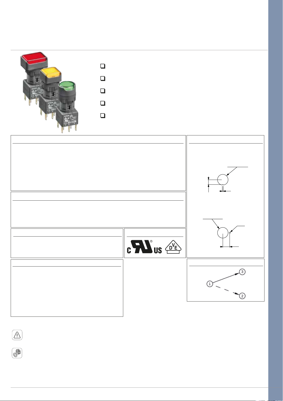
A01 series
Pushbutton switches & indicators
Distinctive features and specifications
Panel Sealed to IP65
Single pole to four pole changeover
Custom engraving or film legends options
Push on tab terminals
6A 250VAC
A01_AX1607USR1
ELECTRICAL SPECIFICATIONS
• Current/Voltage Rating : 10mA 5VAC min, 6A 250VAC, 6Amp 12VDC
• Initial Contact Resistance : 10mΩ max at 1A 4VDC
• Insulation Resistance : 50MΩ min
• Dielectric Strength : 750V between open contacts, 5KV live to accessible
• Electrical Life : 50,000 cycles min
• Contact Gap : >1mm (0.039)
• Insulation : Class 2
• Lamp Life : LED, 60,000 hours to 75% relative luminosity filament, approx. 5000 hours
neon, approx. 10,000 hours
MECHANICAL SPECIFICATIONS
• Mechanical Life : (operator) Momentary, 1 million cycles, maintained 100,000 cycles
• Lamp : Midget grove T1 ¾ filament, neon or LED
• Terminals : Solder/quick connect 2.8mm (0.110)
GENERAL SPECIFICATIONS
AGENCY APPROVALS
• Operating Temperature : -20°C to +55°C
• Solder Heat Resistance : 350°C for 5 seconds
• Sealing : Panel sealed to IP65, rear of panel IP40
MATERIALS
• Screens : PC
• Reflector Assembly : PC
• Operator : PBT
• Nut : ABS
• Camtrack Momentary : PPE
• Camtrack Maintained : PPSU
• Switch Block 1 & 2 Pole : PBT
• Switch Block 3 & 4 Pole : PEI
• Contacts : Gold plated silver
PANEL CUT OUT
Round & Square bezel
operators only
0.00/+0.30
Ø16.00
.000/+.011
(.629 DIA )
1.50
7.25
(.285)
(.059)
Rectangular bezel
operators only
0.00/+0.30
Ø16.00
.000/+.011
(.629 DIA )
(.078 DIA)
10.50
(.413)
Ø2.00
Max panel thickness 8mm (0.314)
CIRCUIT
Dimensions :
first dimensions are in mm while inches are shown in brackets.
Refer to the following pages for further information.
Mounting accessories : standard hardware 1 nut and 1 sealing washer.
The company reserves the right to change specifications without notice.
APEM www.apem.com 1
Page 2
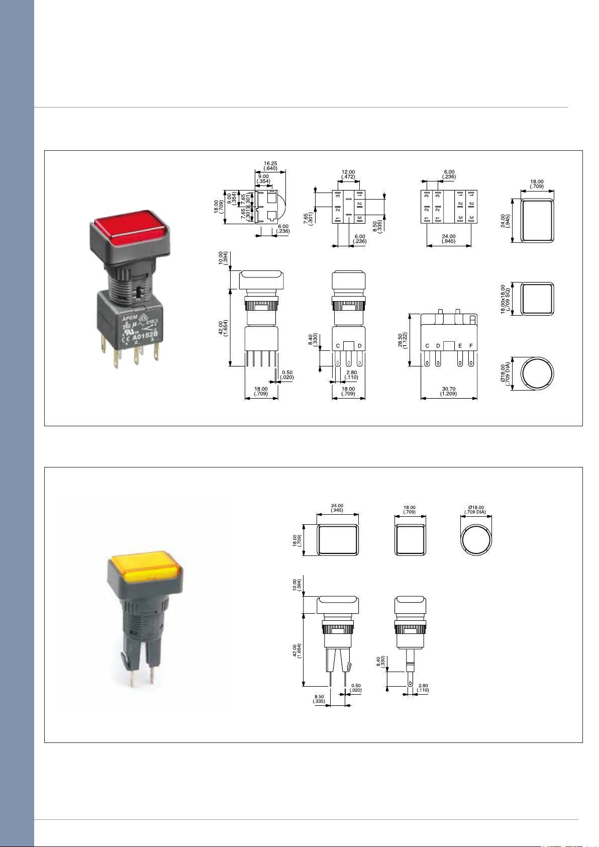
A01 series
Pushbutton switches & indicators
Panel cut-out Ø16 (0.755)
Pushbutton
Indicator
APEM www.apem.com 2
Page 3
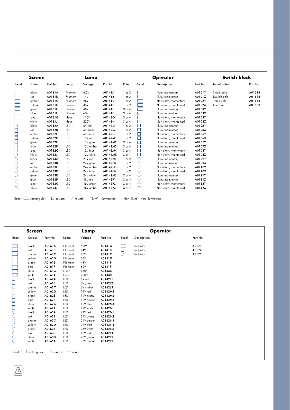
Pushbutton
A01 series
Pushbutton switches & indicators
Overview
+
(if required)
+ +
Indicator
+ +
Unsealed switches & indicators (IP40) suffix 01 to the end of the part number.
Screen engraving insertable legends, & bi-color LED’s please contact APEM
APEM www.apem.com 3
Page 4
Pushbutton switches & indicators
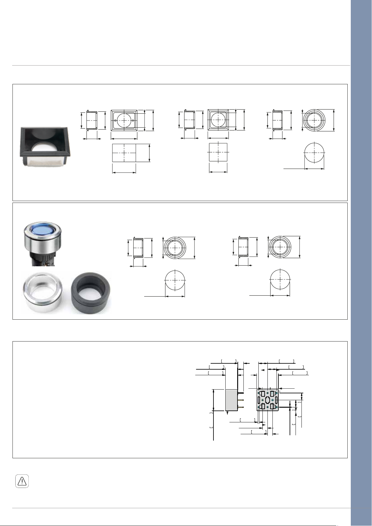
Flush mount bezels
Dark grey plastic material – supplied with sealing washer
A01 series
Accessories
18.10
(.712)
12.00
(.472)
Rectangular : A01FM1
Anodised aluminium/matt black
20.40
(.803)
29.80
(1.173)
+0.20
26.70
0.00
+.008
(1.051 )
.000
18.15
(.715)
11.00
(.433)
Ø16.00
(.630DIA)
.000
0.00
+0.20
+.008
20.60
(.811 )
Ø22.00
22.20
(.874 )
23.80
(.937)
(.866 DIA)
+0.20
+.008
Ø16.00
0.00
.000
(.630DIA)
18.10
(.712)
12.00
(.472)
20.40
(.803)
23.80
(.937)
+0.20
20.60
+.008
(.811 )
.000
0.00
Ø16.00
(.630DIA)
23.80
(.937)
18.15
(.715)
11.00
(.433)
(.874 )
Square : A01FM Round : A01FM2
18.15
Ø25.00
(.984 DIA)
(.715)
11.00
(.433)
Ø16.00
Ø22.00
(.866 DIA)
+0.20
22.20
0.00
+.008
(.874 )
.000
(.630DIA)
Ø22.00
(.866 DIA)
22.20
Ø16.00
+0.20
0.00
+.008
.000
Ø25.00
(.984 DIA)
(.630DIA)
Ø25.00
(.984 DIA)
PCB Sockets
Number of Poles Part No.
Single pole, non illuminated : A01PC1
Double pole, non illuminated : A01PC2
Single pole, illuminated : A01PC3
Double pole, illuminated : A01PC4
Indicator : A01PC5
Dimensions :
Refer to the following pages for further information.
first dimensions are in mm while inches are shown in brackets.
(.167)
5,00 0,197
10,25 0,404
10,50 0,413
7.65
(.301)
0
18,25 0,719
0.80
(.031)
236
Round matt black : A01FMMG Round natural anodised : A01FMM
1,10 0,043
4,25 0,167
4,25 0,167
7,65 0,301
7,65 0,301
18,40 0,724
7.65
(.301)
6,00 0,236
6,00 0,236
The company reserves the right to change specifications without notice.
APEM www.apem.com 4
Page 5
A01 series
Pushbutton switches & indicators
Accessories
Flap guards
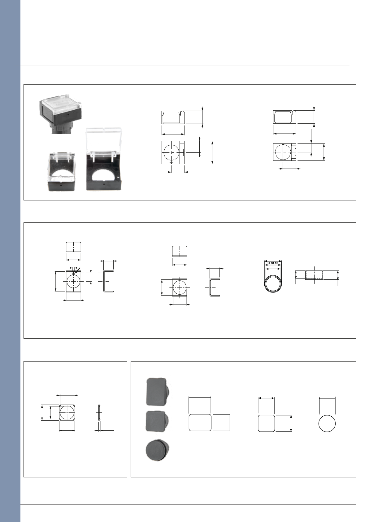
13.50
(.531)
24.00
(.945)
12.00
(.472)
24.00
13.65
(.537)
(.945)
24.00
(.945)
13.65
(.537)
9.00
13.50
(.531)
(.354)
18.00
(.708)
To fit rectangular bezel : A01FG1
Aluminium bezel protection guards
18.00
(.708)
Ø2.00
(.078DIA)
24.00
(.944)
Ø16.00
(.630DIA)
Rectangular : A01MG1
10.15
(.399)
12.00
(.472)
18.00
(.708)
18.20
(.717)
Ø16.00
(.630DIA)
Square : A01MG Round natural anodised: A01MG2
Anti rotation ring Blanking plugs
12.00
(.472)
To fit round & Square bezel: A01FM2
Ø 19.60
Ø 16.05
9.00
10.00
Matt black : A01MG2G
24.0
(.946)
18.0
(.709)
18.0
(.709)
18.0
(.709)
Ø18.0
(.709 DIA)
18.00
(.708)
14.75
(.580)
Ø16.00
(.629DIA)
18.00
(.708)
2.00
(.078)
Rectangular : A0131 Square : A0132 Round : A0133
A01LW
APEM www.apem.com 5
Page 6
Installation guide
A01 series
Pushbutton switches & indicators
Installation & tools
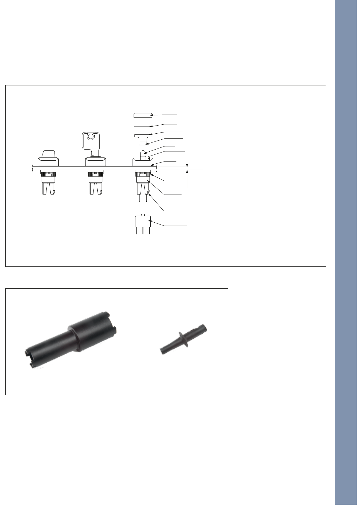
PANEL MOUNTING ASSEMBLY
• Drill/punch hole shaped as shown on
page one.
• Assemble front operator through hole,
t fxing nut and tighten to a maximum
torque of 0.8Nm using tool No. 30-0001.
• Wire chosen switch block as required
and slide onto operator until
latch engages.
• Fit bulb if required using tool
ROTARY
LEVER SWITCHES
KEYLOCK
SWITCHES
PUSHBUTTONS
& INDICATORS
SCREEN
LEGEND
REFLECTOR
LOCATING
SLOT
BULB
POLARISING
DOT
PANEL
SEAL
No. 30-0002.
FIXING
NUT
OPERATOR
8.00 max
(.314 max)
• Snap screen onto reector assembly
with legend in between if required
and snap onto front operator,
take care to line up the locating slot
with the polarising dot and not to
LATCH
damage the internal seal
• To place/remove the bulb use the bulb
SWITCH BLOCK
extractor 30-0002.
SWITCH BLOCK ASSEMBLY
To assemble switch block to the operator, firstly, take care to line up the switch block with the back of the operator.
Once in position slide on to the back of the operator. N.B. Ensure latch is fully engaged correctly onto the switch block.
To remove switch block, depress the latch and slide the switch block off the operator.
Tools
Nut fixing key Bulb remover
30-0001 30-0002
APEM www.apem.com 6
 Loading...