

Apelem Rafale EV 30 Service manual

Rafale EV 30
Mobile Radiographic Unit
Service Manual
Parc Scientifique G.Besse, 175 allée Von Neumann 30035 Nimes cedex 1
+33 (0)4 66 29 09 07 FAX +33 (0)4 66 29 71 23
e-mail export@apelem.com
Site web: www.apelem.com
Original version of this manual is in Italian language therefore, for further information and clarification, please
refer to the Italian one.
COD. 04.02.007.005 – REV.1 V
ALID FROM
01
ST
APRIL
2011

D
OCUMENT REVISION STATUS
Document code: 04.02.007.005
Revision 1 – Valid from 01st April 2011
• Doc. 10551 - Valid from 01st April 2011
• Doc. 7819 - Valid from 01st July 2004

Service Manual
Index
Section 0
Doc. 10551 Page 1 of 69

Service Manual
I
NDEX
General index
Section 0 - Index
(doc. 10551)
Valid from 01st April 2011
Section 1 – Installation Page
1 Introduction 6
2 Unpacking 7
2.1 Packing with cellophane 7
2.2 Packing with carton 9
2.3 Packing with wood crate 10
3 Electrical connections 11
4 Acceptance test 11
4.1 Checking cables and connectors 11
4.2 Mechanical checks 11
4.3 Electrical checks 12
Section 2 – Maintenance
1 Routine maintenance 16
1.1 General recommendations 16
1.2 Frequent checks and inspections 17
1.3 General checks and inspections 17
1.4 Cleaning and disinfection 18
2 Special maintenance 19
2.1 Dismantling the Unit Casings 19
2.2 Extraordinary Mechanical Maintenance 21
2.3 Mechanical Adjustments 22
2.3.1 Parking brake 22
2.3.2 Anti-tilting System 22
2.3.3 Arm-X-ray tube head Balancing System 24
Section 0
Page 2 of 69 Doc. 10551

Service Manual
I
NDEX
2.3.4 Locking the Arm in the Transport Position 26
2.3.5 X-ray tube head-Collimator Assembly Rotation 26
2.3.6 Centring the X-ray tube head – Collimator Assembly 28
2.4 Electrical troubleshooting 29
2.5 Thermomagnetic Circuit-breaker 30
2.6 Replacement of Components 31
2.7 List potentiometers 32
2.8 List leds 33
2.9 List fuses 34
3 Spare parts 34
Section 3 – X-ray settings
1 Introduction 36
1.1 Dip switch 37
2 Rotating anode stator power supply adjustment 37
3 Set-up procedure 38
3.1 Service menu 39
4 kV adjustment 39
4.1 Adjustment “set-up” voltage 39
4.2 Adjustment of maximum kV setting safety 40
4.3 Checking maximum kV setting safety 40
5 Adjustment of the filament current 41
5.1 Adjustment of filament current 42
6 mAs adjustment 44
7 Adjustment of the battery voltage 45
8 Checking the radiographic parameter 46
8.1 Checking kV and mAs during radiography 46
Section 4 – Drawings
Annex – 115Vac Power supply (optional)
Doc. 10551 Page 3 of 69
Section 0

Service Manual
I
NDEX
Section 0
Page 4 of 69 Doc. 10551

Service Manual
Installation
Section 1
Doc. 10551 Page 5 of 69

Service Manual
I
NSTALLATION
1 I
NTRODUCTION
The installation procedure consists of different operations to be carried out in the order shown in
the flow chart below.
Unpacking
Electrical connection
The various operations indicated are described in detail in the following paragraphs.
N
OTE
: the radiological system is normally pre-installed and configured in the factory according to
the specific requirements of the customer. Certain adjustments may, however, be necessary when
components are replaced.
The whole machine parameter adjustment procedure is described in detail in this manual.
After 30 minutes of non-use, the equipment automatically switches into stand-by
mode, that means the capacitors battery is unloaded; the words “Stand By” appears
on the display of control console and the value of the battery voltage is zero.
!
Pressing any key of control console, the battery reloads to the maximum value and it
Acceptance test
is possible to make X-Ray exposure. During capacitors battery loading the words
“Waiting” will appear on control console display.
Section 1
Page 6 of 69 Doc. 10551

Service Manual
I
NSTALLATION
2 U
NPACKING
The radiological system is packed in a single case containing all the parts of the apparatus. To
unpack the unit, proceed as described on the following paragraph, according to the type of packing:
➠ simple pallet with cellophane – SEE § 2.1
➠ pallet with carton – SEE § 2.2
➠ wood packing crate – SEE § 2.3
If necessary, follow the unpacking procedure backwards to pack the unit again.
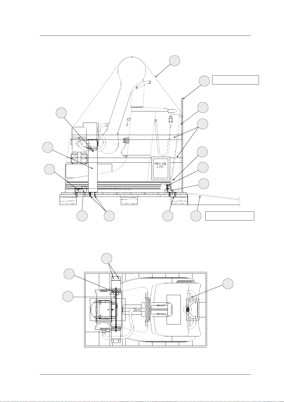
2.1 P
ACKING WITH CELLOPHANE
1. Cut the tape (4) and remove the slide (5) –
S
EE FIGURE
1
2. remove the protective bag (6)
3. unscrew the four self-threading screws (7) which fix the pedal fixing bracket (8) to the
bottom of the crate
4. unscrew the four screws (9) which fix the pedal fixing bracket (8) to the mobile unit
5. mount the tilting pedal (10), located inside the cassette holder (11), by means of the
screws and washers previously disassembled from the bracket (8)
6. free the X-ray Tube Head fixing brackets (12) from the tie-rod (17) -
S
EE FIGURE
working on nuts (13)
7. unscrew the self-threading screws (14) and remove the X-ray Tube Head fixing brackets
(12)
8. put the slide (5) on the floor, as shown in
F
IGURE
1
9. slowly move the mobile unit towards the slide (5), keeping the "Dead-Man-Control"
brake lever (18) pressed. Note that the front wheel (15) of the unit must come out of its
packing housing (16)
10. let the unit move slowly from the slide (5) till its complete positioning on the floor and
release the brake lever (18).
2
-
Section 1
Doc. 10551 Page 7 of 69
Service Manual
I
NSTALLATION
6
5
Packing position
13
11
4
12
10
15
9
8
16
14
7 5
Floor position
F
IGURE 1 - LATERAL VIEW
14
13
18
17
F
IGURE 2 - VIEW FROM ABOVE
Section 1
Page 8 of 69 Doc. 10551
Service Manual
I
NSTALLATION
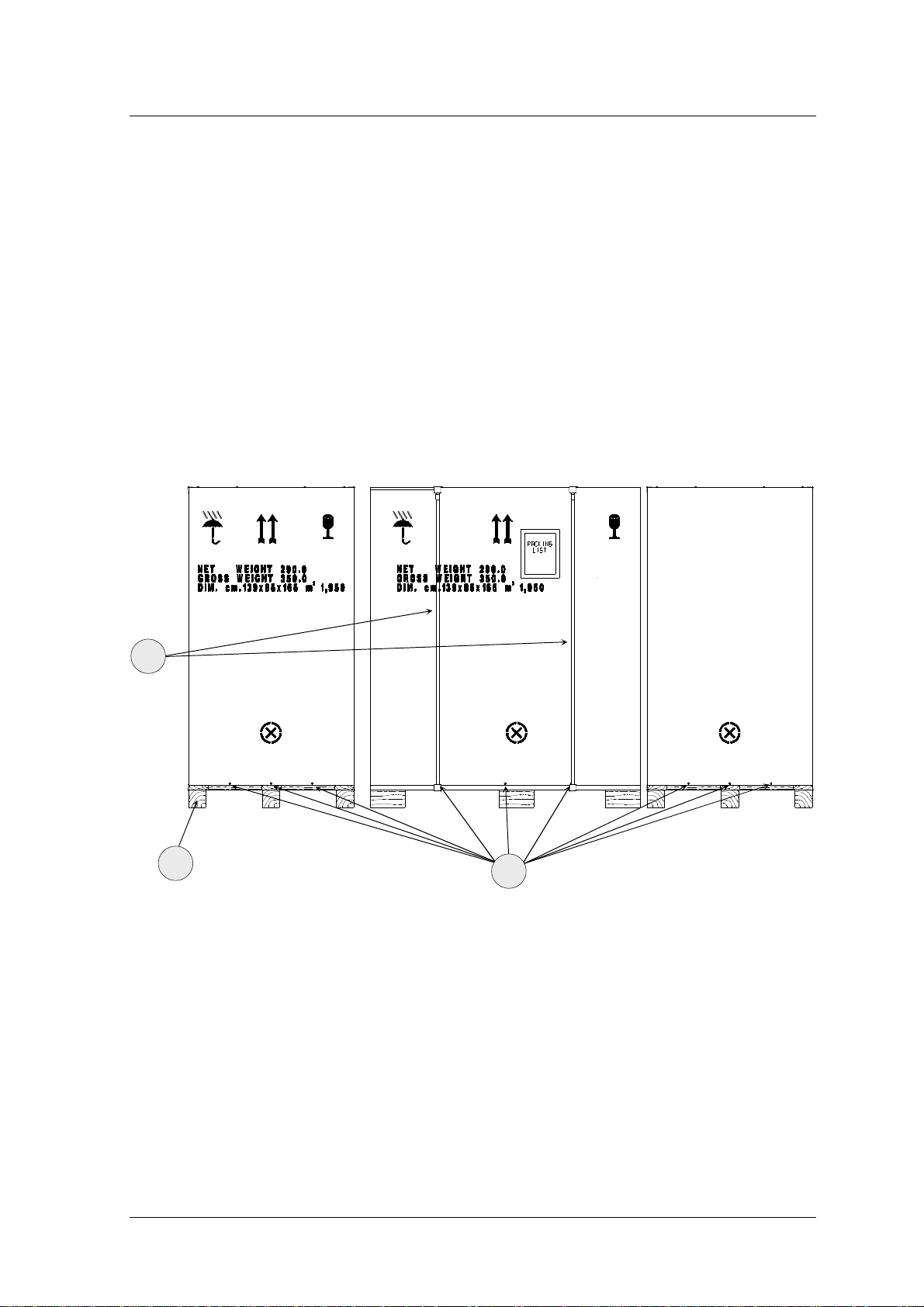
2.2 P
ACKING WITH CARTON
1. Remove the screws (1) -
S
EE FIGURE
3
-
which fix the packing carton to the crate pallet
(2)
2. cut the band (3)
3. remove the carton packing from its housing; the mobile unit is as shown in
4. proceed according to the packing with cellophane procedure (§ 2.1).
3
F
IGURE
1
2
1
F
IGURE 3 - PALLET WITH CARTON
Section 1
Doc. 10551 Page 9 of 69

Service Manual
I
NSTALLATION
2.3 P
ACKING WITH WOOD CRATE
1. Dismantle the crate cover (1) –
S
EE FIGURE
4
2. remove the crate walls: be careful not to ruin the wall (5) that has to be used as slide; the
mobile unit is as shown in
F
IGURE
1
Note: in the wood packing case, the slide (5) is not mounted as shown in F
because it is substituted by the wall (5), previously mentioned
3. proceed according to the packing with cellophane procedure (§ 2.1).
1
IGURE
5
1,
F
IGURE 4 - WOOD CRATE
Section 1
Page 10 of 69 Doc. 10551

Service Manual
I
NSTALLATION
3 E
The power supply single-phase alternate voltage and maximum absorbed current values are
reported both on the unit label and on the technical data in the user manual.
Make sure that the power supply socket is approved for the values reported on the
4 A
The A
LECTRICAL CONNECTIONS
!
unit label
CCEPTANCE TEST
CCEPTANCE TEST
➠ checking cables and connectors
➠ mechanical checks
➠ electrical checks
includes three main kinds of operations:
4.1 C
Visually control each cable and each connector, checking that there are no interruptions and/or
crushing.
4.2 M
The mechanical checks include the following operations:
HECKING CABLES AND CONNECTORS
A.1 Power supply cable of the unit
A.2 Radiography control pushbutton cable
A.3 Connection cable between unit/X-ray Tube Head
ECHANICAL CHECKS
➠ MOVEMENTS: all the movements foreseen must be possible without excessive force or
jerks
➠ B
RAKES
: all the movement locking brakes must be operating and easily applied
Section 1
Doc. 10551 Page 11 of 69

Service Manual
I
NSTALLATION
➠ S
Follow the procedure below:
B.1 Parking brake of the radiological unit: push the unit without activating the parking
B.2 Turning the wheels of the radiological unit: release the parking brakes of the unit by
B.3 Correct operation of the anti-tilting assemblies:
OUNDNESS
: check that there are no breakages and/or damage which might have
jeopardised operation and safety of the apparatus.
brake on “dead-man control” (21) and check that the unit does not move
pressing the “dead-man” lever (21). Move it a few metres and check that there are no
movement imperfections and that there are no noises due to the wheels turning.
Tilting: place the unit on an horizontal surface in the transport position, carry out
the tilting operation (S
EE THE USER’S MANUAL
) and check that the unit lowers
over the rear but with slight friction due to the anti-tilting system.
Flag movement: loosen the arm brake by means of the handle (4), lift the arm/X-
ray tube head assembly into the horizontal position and turn it 90° onto one side.
Then check that the unit does not tilt onto the side in question. Repeat the
procedure on the opposite side.
B.4 Soundness of the control console: check that there are no scratches or breakages on the
surface
B.5 Soundness and fixing of the casings: check that there are no scratches or breakages on
the casings and that these are coupled correctly without any visible openings.
B.6 Balancing the pantograph arm: move the arm/X-ray Tube Head assembly vertically
and check that it remains blocked for release by the operator in all the positions.
4.3 E
LECTRICAL CHECKS
With regard to the electrical part, correct operation of the following must be checked:
➠ S
AFETY DEVICES
➠ S
IGNALS
NOTE
Section 1
Page 12 of 69 Doc. 10551
: Remove the carters to carry out the electrical checks (S
EE SECTION 2 -
§2.1).

The procedure is described below:
Service Manual
I
NSTALLATION
C.1 P
C.2 I
C.3 S
C.4 L
C.5 D
!
C.6
C.7 X-
OWER SUPPLY
NITIAL TEST
OFTWARE:
OADING:
: connect the unit to the mains power supply;
: check that the initial automatic test is correct of the unit;
check that the visualization of installed software;
check that the switching on the unit appears the increment of voltage on
display until 320 V. The complete loading of the capacitors battery is ready in about
40/45 sec;
ISCHARGING:
switch the unit off and check the complete discharging of the
capacitors battery by means the switching off the LD3 led mounted on S25 board;
Do not carry out switching the unit On and Off
SET-UP DATA IN MEMORY:
SET-UP data are in according with data selected (S
RAY TUBE FORMATION:
enter on SET-
UP (SEE SECTION
EE SECTION 3 - § 3 –
3 - § 3) and check that the
T
ABLE
5
);
when not in use the unit for a long time, before to use the
unit normally, carry out the “formation” of the X-ray tube with a serial of exposures
using the following data (carry out for each value of kV and mAs 10 exposures and
keep a pause of 1 minute between an exposure and another one):
40 kV 100 mAs
50 kV 80 mAs
60 kV 63 mAs
70 kV 63 mAs
80 kV 50 mAs
90 kV 50 mAs
100 kV 40 mAs
110 kV 40 mAs
120 kV 40 mAs
Section 1
Doc. 10551 Page 13 of 69

Service Manual
I
NSTALLATION
During this formation check with oscilloscope the value of kV [S19 board Tp11 (-); Tp3 (+) ] and
mA [S19 board: Tp11 (-); Tp6 (+) ] on inverter. Select the oscilloscope in the following way:
C
HANNEL
C
HANNEL
B
ASE TIME
A: 1 V/DIV ( 1V read is equal to 50 mA)
B: 1 V/DIV ( 1V read is equal to 20 KV)
: 25ms/DIV
In case kV wave form presents high voltage discharge or you hear discharge inside Xray tube interrupt the sequence, wait few minutes before starting again; repeat the
initial formation checking that the fuse F7 is not interrupted (100A) (
ELECTRICAL DRAW
);
SEE.
!
Warning: presence of 320 Vdc voltage!
C.8 E
XPOSURE TIME:
check that during exposure time the X-ray passage led until the end
of exposure the display shows the real exposure time in seconds.
C.9 S
TAND BY:
let the equipment switched on in “Stand by” mode, that means without
make X-Ray exposure, and verify that after 30 minutes the capacitors battery is
unloaded, as explained in § 1. Press any key of control console to restore the
capacitors loading and repeat the whole procedure for a total time of at least 4 hour.
Section 1
Page 14 of 69 Doc. 10551

Service Manual
Maintenance
Section 2
Doc. 10551 Page 15 of 69

Service Manual
M
AINTENANCE
1 R
recommendations have the aim of helping the operator to keep the apparatus in good working and
safe conditions during service.
The system contains mechanical parts subject to wear according to use: following prolonged use,
wear on parts may decrease safety during use. For this reason, it is essential for the checking and
maintenance operations indicated below to be carried out consistently to protect the operators and
patients against any damage caused by mechanical breakdowns.
Correct adjustment of the electrical and electronic systems has a direct influence on the operation
of the system, on the quality of the image and on the electrical safety of the system, as well as on
the level of exposure to radiation the operators and patients are subjected to.
The M
interventions to be carried out by specialised personnel authorised by the manufacturer. All
OUTINE MAINTENANCE
1.1 G
The radiological system requires regular checks and maintenance. The following
ENERAL RECOMMENDATIONS
AINTENANCE PROGRAMME
, described in the following paragraphs, consists of controls and
maintenance operations are charged to the owner of the apparatus.
Should it be necessary to replace components or parts which may in any way
!
condition the safety of the machine, only use original spare parts.
Section 2
Page 16 of 69 Doc. 10551

Service Manual
M
AINTENANCE
1.2 F
REQUENT CHECKS AND INSPECTIONS
The operating personnel must be suitably trained to be able to carry out the daily and weekly
checks indicated in
T
ABLE
1
.
The other 6-monthly and annual controls described in this chapter and the interventions described
in the following chapters are reserved for qualified and authorised personnel of the technical
assistance service.
T
ABLE
1
I
NTERVAL
D
AILY
CHECKS
W
EEKLY
CHECKS
6-M
C
HECKS
A
NNUAL
CHECKS
ONTHLY
C
HECK
Operation of the signals, displays and LEDs
Operation of the stationary brake
Check that the warning and danger labels are intact
Absence of oil leaks from the X-ray tube head
Absence of unusual noises in the X-ray tube head during X-ray
emission
General checks and inspections S
Efficiency of the unit as described in the extraordinary mechanical
maintenance
R
EFERENCE
S
ERVICE MAN. – SECTION
U
SER’S MAN. – SECTION
ERVICE MAN. – SECTION
S
ERVICE MAN. – SECTION
2 - § 4.2
2 - § 1.7.1
2 - § 1.3
2 - § 2.2
1.3 G
ENERAL CHECKS AND INSPECTIONS
Every six months, and in any case according to local legislation in force, the procedures
indicated in the A
CCEPTANCE TEST
must be carried out completely.
Moreover the checks listed below must be added:
D.1 AC and DC power supply
D.2 Protection earth
D.3 Fixing and general state (dust and corrosion) of the boards and of the connectors
D.4 Centering of the X-ray tube head/collimator assembly (S
EE SECTION 2 - §
2.3.6)
Section 2
Doc. 10551 Page 17 of 69

Service Manual
M
AINTENANCE
1.4 C
Products with an high content of alcohol, corrosive and/or abrasive detergents or solvents must
not be used to clean the surfaces of the apparatus.
To disinfect the system, only use methods in compliance with the laws in force regarding
disinfection and protection procedures against explosion.
To carry out the cleaning and disinfection operations, take the following precautions:
!
LEANING AND DISINFECTION
➠ turn the system off and disconnect the mains power supply cable
➠ make sure that no liquid gets into the apparatus so as to avoid any short-circuits or
corrosion of the electrical and electromechanical parts.
The unit has not to be used in presence of anaesthetic and/or infiammable
disinfectant and cleaning products.
If, producing explosive gaseous, mixture, are used, make sure that gases are
dispersed before switching on the unit.
Section 2
Page 18 of 69 Doc. 10551

Service Manual
M
AINTENANCE
2 S
Any maintenance operation requires the external casings of the unit to be dismantled as
indicated below (
PECIAL MAINTENANCE
2.1 D
ISMANTLING THE UNIT CASINGS
S
EE FIGURE
➠ dismantle the cassette-holder basket (1):
•
open the basket, releasing it from the relative locking jacks (2)
•
release the respective hinges (3) located under the basket, by means of the pins on
them
•
to completely remove the basket, it is necessary to release the earthing cable fixed to
the sheet of the basket
➠ dismantle the plastic nuts (4) which lock the assembly casing to the keyboard (5).
➠ loosen and completely dismantle the release handle (6) of the arm/X-ray tube head
rotation
5
):
ATTENTION: from this moment, the arm can rotate freely so do not move the unit
because a sudden movement of the arm might occur, endangering people in the
!
vicinity
➠ release the two casings (7) and (8) of the arm
➠ unscrew the screws (9) and (10) and dismantle the relative shaft casings (11) and (12)
➠ dismantle the tilting handle (13), if provided
➠ release the assembly casing with the keyboard (5), which was released previously (see
instruction n°2). To remove the assembly completely, disconnect the cables connected to
the keyboard
➠ dismantle the casing with the cable support (14). To remove the casing completely, it is
necessary to release the earthing cable fixed to the aluminium cable support
➠ dismantle the remaining casings (15) and (16) from the rubber strip section of the base.
At this point the unit is completely accessible for any maintenance operations.
Section 2
Doc. 10551 Page 19 of 69

Service Manual
M
AINTENANCE
To remount the casings, repeat the procedure described above in reverse order, taking care to
couple the casings correctly in their relative seats and grooves.
5
13
12
10
1
3
2
4
8
11
10
9
7
15
14
16
F
IGURE 5
Section 2
Page 20 of 69 Doc. 10551
– E
XPLODED VIEW OF COMPACT
6

Service Manual
M
AINTENANCE
2.2 E
Apart from the ordinary maintenance procedures (
indicated below (
adjust/replace the component (
XTRAORDINARY MECHANICAL MAINTENANCE
S
EE
§
1), it is advisable to carry out the checks
S
EE FIGURE
6
) annually, or following heavy use of the apparatus and, if necessary,
S
EE
§
2.3 and § 2.6).
Before starting, dismantle the unit casings as explained in § 2.1.
➠ Pantograph arm: check that there is grease in the moving parts. When there is any dirt or
dust, remove the remaining grease and add some new grease as explained below:
•
in the rotation points of the tie-rods (1) and (2) of the pantograph system: Loctite 8150
(A) type grease
•
in the chain supporting part (3) on the cam (4): common C2 type grease (B)
Also check that there are no worn or broken parts which need replacement
➠ X-ray tube head cables: check that the connection cables to the X-ray tube head have no
cuts or stripping, particularly in the points corresponding with rotation of the shaft and
with vertical arm movement
➠ vulcanized wheels: clean the internal surface of the 2 wheels (5) and (6) and the contact
surface of the pads (7) and (8) with degreasers to guarantee better locking of the unit
➠ general check: check correct fixing of the parts mechanically assembled and screwed up.
A
1
2
A
3
B
4
8
6
F
IGURE
6 - S
HAFT WITH ARM – BASE WHEELS
7
5
Section 2
Doc. 10551 Page 21 of 69

Service Manual
M
AINTENANCE
2.3 M
ECHANICAL ADJUSTMENTS
2.3.1 P
ARKING BRAKE
(
S
EE FIGURE
7
)
➠ The mobile unit remains braked:
•
the tension of the rope (1) is not sufficient: adjust it by means of the tensiometer (2)
•
the connection rod (3) to the pad (13) is not released or adjusted correctly:
unscrew/screw up the rod, position the pad correctly (the space between the pad and
wheel must be between 0.5 and 1 mm) and then lock using the relative counter nut (4)
➠ the mobile unit does not remain braked:
•
the two thrust dowels (14) of the springs (15) are not adjusted correctly and the pad
(13) does not press correctly against the wheel (10): adjust by means of the dowels; if
the spring (15) is lacking grease (common C2 type), add the amount needed
➠ when the wheels of the unit turn, there are noises or intermittent jerks:
•
carry out the adjustments indicated in the two previous points.
2.3.2 A
NTI-TILTING SYSTEM
(
S
EE FIGURE
7
)
➠ In the flag position 90° to the side, the gas spring is not released and the machine is
unstable, attempting to tilt over:
•
the tension of the spring control ropes (11) is insufficient: adjust by means of the tierods (9)
•
the cam/bearing system (5) controlled by rotation of the shaft (8) does not move
correctly: grease the parts if necessary, or replace the return spring (6) or the bearing
(7) activated by the cam anchored to the shaft
➠ it is not possible to carry out the Tilting function:
•
the gas spring control rope (11) is broken: replace it
•
the gas spring (12) is faulty: replace it.
Section 2
Page 22 of 69 Doc. 10551

Service Manual
M
AINTENANCE
7
5
2
1
4
8
6
3
5
9
12
11
10
14
15
13
F
IGURE
7 - E
XPLODED VIEW OF MACHINE
Doc. 10551 Page 23 of 69
Section 2

Service Manual
M
AINTENANCE
2.3.3 ARM-X-
RAY TUBE HEAD BALANCING SYSTEM
(
SEE F
IGURE
8
)
➠ Adjustment of the arm clutch
The balanced suspension system of the mobile unit allows smooth vertical movement of
the arm and therefore of the x-ray assembly. This system has been studied and realised to
reduce the need for maintenance to a minimum.
However, as time passes and due to continual stresses, the balancing system may lose a
minimum amount of its efficiency. It is usually sufficient to adjust the boom pin (2)
which acts directly on the clutch plates (1)
➠ Adjustment of the counterweight spring force
If the previous operation is not sufficient to restore the optimal balancing condition, it is
necessary to carry out an adjustment of the spring thrust (5) as described below:
•
with a setscrew spanner, loosen the boom pin (2), watching out for sudden and
undesired movements of the arm and of the x-ray assembly which takes the arm to the
highest possible position
•
just for device with 115V power supply, disassemble the 115V power supply group
(S
EE SECTION 4 - EXPLODED DRAWINGS
)
•
with the help of a second person, lower the arm until the nut (7) in the window (6) is
accessible
•
using a spanner (mm 12), screw up or loosen the nut (7) through the window (6)
present on the shaft with the spring (4). This operations modifies the pre-load applied
to the compression spring (5)
•
to check correct balancing of the spring, make sure that the arm can stay in the
horizontal position without any support
•
on completion of balancing, tighten the boom pin (2) to take the clutch back to a
compression value which, although keeping the arm stopped in any position in a stable
way, allows its movement without difficulty (balancing to be checked with the arm
casing mounted)
•
on completion of the operations, put the casings back into their original position.
Section 2
Page 24 of 69 Doc. 10551

Service Manual
M
AINTENANCE
1
3
3
2
4
5
6
7
F
IGURE
8 - E
XPLODED VIEW OF THE PANTOGRAPH ARM
Doc. 10551 Page 25 of 69
Section 2

Service Manual
M
AINTENANCE
2.3.4 L
OCKING THE ARM IN THE TRANSPORT POSITION
(
S
EE FIGURE
8
)
➠ If no lock is noticed or the arm tends to rise during the movement stage when putting the
unit into the transport position (S
EE USER’S MANUAL
) with the arm completely retracted
downwards, the arm stops (3) are worn, and must therefore be replaced.
2.3.5 X-
RAY TUBE HEAD-COLLIMATOR ASSEMBLY ROTATION
(
SEE F
IGURE
ATTENTION – In cases where dismantling components of the X-ray tube head
assembly or the assembly itself are foreseen, make sure the arm is locked so as to
!
prevent any sudden and involuntary movements of the arm which would endanger
the technician.
➠ 360° rotation is difficult or not correctly adjusted:
•
inside the hole where the pin of the chrome-plated bracket (1) is housed dirt has
accumulated due to wear on the parts in contact with the system of clamps (2) and (3):
9
)
dismantle, clean carefully and lightly grease. (If this is not sufficient, replace the
clamps). Then remount and lock using the correct force – just enough to make rotation
of the bracket possible.
➠ X-ray tube head inclination ( -15° ÷ +105° ) is difficult or not correctly adjusted, or the
X-ray tube head does not remain blocked in the position for operator release:
•
dismantle the lateral goniometer (4) and clean it of any dirt caused by wear on the
clutch plate (5), then remount it locking the screws (6) with the correct force to
prevent rotation movement blocking.
•
to guarantee correct pressure of the Belleville washers (7) which press on the clutch
plate, it is also possible to increase or decrease the number of Belleville washers (7)
•
if cleaning is not sufficient, the clutch plate (5) may be worn, and must therefore be
replaced.
Section 2
Page 26 of 69 Doc. 10551

Service Manual
M
AINTENANCE
1
5
4
6
7
2
1
3
4
F
IGURE
9 - X-
RAY TUBE HEAD
Doc. 10551 Page 27 of 69
Section 2

Service Manual
M
AINTENANCE
2.3.6 C
ENTRING THE X-RAY TUBE HEAD – COLLIMATOR ASSEMBLY
➠ Preliminary centring:
•
turn the x-ray assembly so that the x-ray output is turned upwards
•
position the adapter ring of the collimator and screw it onto the x-ray assembly,
without tightening the fixing screws completely so that the ring itself can make small
movements
•
position the adapter and the centring device inside the ring
•
position the x-ray assembly behind a glass sheet sealed with lead so that the graded
part of the centring device can be seen
•
carry out an exposure and check the position of the luminous dot which appears on the
graded circular scale of the centring device
•
adjust the adapter ring of the collimator so that the luminous dot is exactly in the
centre of the graded circular scale of the centring device
•
lock the ring in question, fully tightening the four screws which fix it to the x-ray
assembly.
➠ Final centring:
•
position a washer at the centre of the collimator and, by means of the collimator light,
position the “Fluorescent Screen” so that its centre coincides with the centre of the
washer
•
carry out an exposure and check that the washer has been impressed on the fluorescent
screen.
Note: For any other centring operations of the collimator, please refer to the T
M
ANUAL
of the collimator.
ECHNICAL
Section 2
Page 28 of 69 Doc. 10551
 Loading...