

Page 1
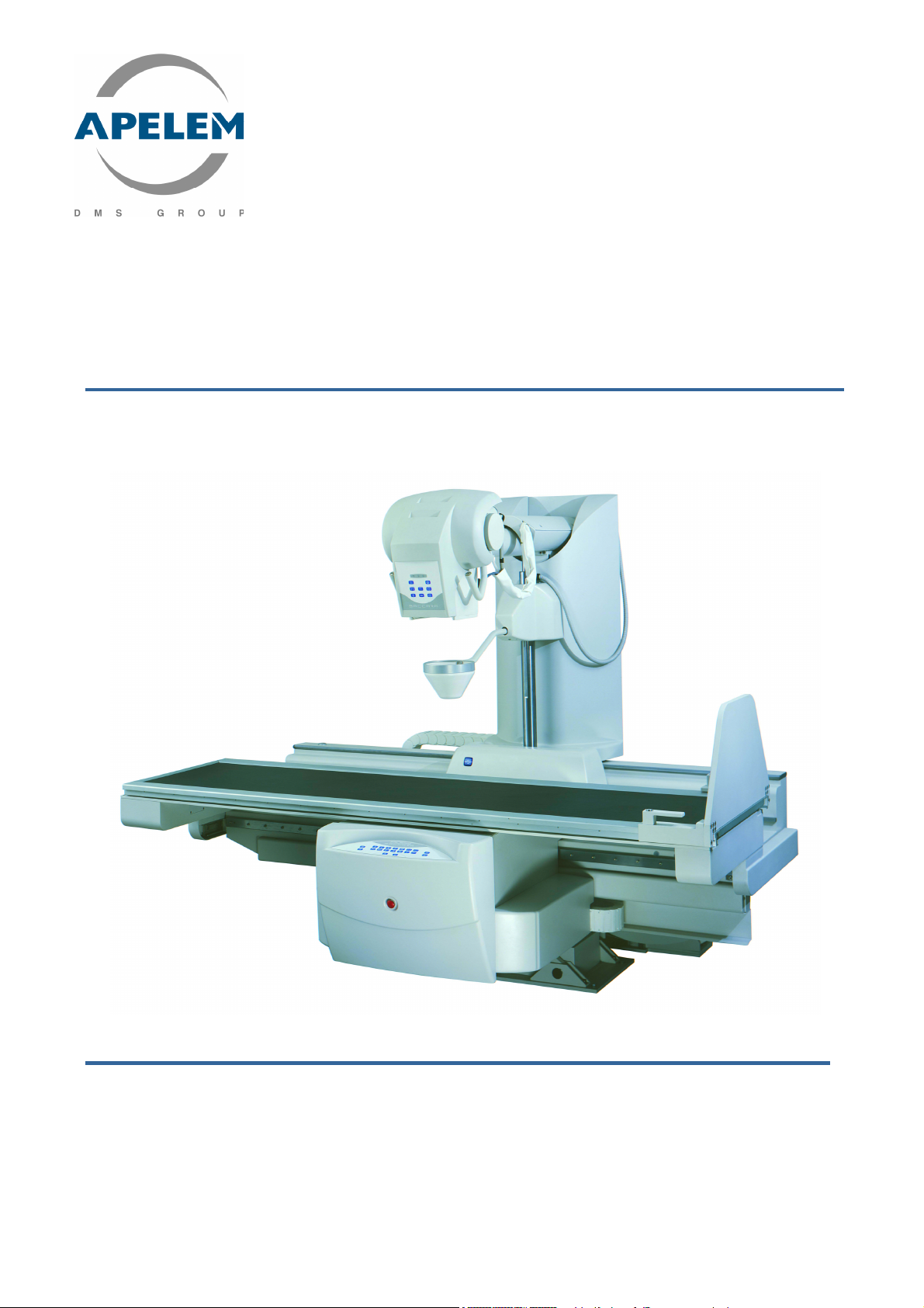
Remote Controlled Tables
BACCARA 90/20 & 90/25 HV
USER’S MANUAL (Ref. 80-40-002- Rev. L – Date January 2006)
APELEM-DMS GROUP Parc Scientifique Georges Besse
175 Allée Von Neumann, 30035 Nîmes cedex 1- France
Tel + 33 (0)4 66 29 09 07 - Fax +33 (0)4 66 29 71 23 - e-mail:
Page 2

REMOTE CONTROLLED TABLES BACCARA 90/20 & 90/25 HV
Page intentionally left blank
BACCARA 90/20 & 90/25 HV
BACCARA 90/20 & 90/25 HVBACCARA 90/20 & 90/25 HV
2/ 54 [Doc: 80-40-002. Rev L.] User’s Manual
Page 3

REMOTE CONTROLLED TABLES BACCARA 90/20 & 90/25 HV
TABLE OF CONTENTS
1. SAFETY AND COMPLIANCE..............................................................................................5
2. PRODUCT DESCRIPTION .................................................................................................11
2.1. BACCARA 90/20.......................................................................................................11
2.2. BACCARA 90/25 HV.................................................................................................17
3. TECHNICAL SPECIFICATIONS......................................................................................... 27
4. CONTROLS AND FUNCTIONS OF BACCARA TABLE ......................................................29
4.1. MAIN CONSOLE........................................................................................................29
4.2. CONSOLE KEYBOARD CONTROLS..........................................................................30
4.3. TABLE CONTROL PANEL ...........................................................................................46
4.4. COLLIMATOR CONTROL PANEL..............................................................................48
5. ERROR CODES ................................................................................................................51
6. POSITIONING AND REMOVING OF ACCESSORIES....................................................... 53
User’s Manual [Doc: 80-40-002. Rev. L] 3/54
Page 4

REMOTE CONTROLLED TABLES BACCARA 90/20 & 90/25 HV
Page intentionally left blank
BACCARA 90/20 & 90/25 HV
BACCARA 90/20 & 90/25 HVBACCARA 90/20 & 90/25 HV
4/ 54 [Doc: 80-40-002. Rev L.] User’s Manual
Page 5
REMOTE CONTROLLED TABLES BACCARA 90/20 & 90/25 HV
1. SAFETY AND COMPLIANCE
The purpose of this user's manual is to provide a set of easy instructions for a proper use of the
system.
All of information contained herein is based on the current version of the system.
APELEM-DMS Group reserves the right to improve and implement changes to the information
herein in order to reflect any changes required by technological enhancements.
1.1. INTENDED USE OF THE UNIT
BACCARA Table has been designed to satisfy the most demanding practitioners in Digital
techniques. Completely multipurpose and extremely efficient, the BACCARA Table in its traditional
version has a spot film device (for 18 x 24 and 36 x 43 cm cassettes) that allows specific and reliable
diagnosis (1/2/3/4 and 5 cuttings and on large sizes of cassettes).
It allows gastro-intestinal examinations, urology, pulmonary, hysterography, lymphography,
skeleton radiography, tomography and pediatrics (the grid is retractable).
This system is especially intended to radiological use.
This X-ray equipment must be used in strict compliance with safety
rules contained in this manual, and cannot be used for other
purposes than those for which it has been designed.
1.2. SAFETY
Only personnel qualified enough to radiations protection methods and trained enough to Xray unit safety and operating rules may use this unit.
It is incumbent upon the operator to use the unit in compliance with safety standards
relating to the installation and the use of X-ray units.
Only trained service personnel authorized by APELEM-DMS Group
may remove the unit covers and only in accordance with the
This equipment is not intended to function in an atmosphere containing explosive gas or
where there exists a danger of explosion.
It is imperative for both patient and operator safety, that the unit be checked every 6
months in order to guarantee its efficiency and its reliability during ten years of its lifetime.
Worn parts may become dangerous; they must be checked and replaced by new ones.
Circuits and safety systems must not be moved for any reason, modified or removed.
Before using the unit, the operator must ensure that all safety devices are in working order.
This X-ray unit may only be used in environments or medical rooms in compliance with the
applicable IEC standards.
instructions contained in the Service Manual.
User’s Manual [Doc: 80-40-002. Rev. L] 5/54
Page 6
REMOTE CONTROLLED TABLES BACCARA 90/20 & 90/25 HV
The unit must not operate when mechanical or radiological faults occur, or when indicators
or warning light are faulty. When the unit is jointly used with other unit, component or module
whose compatibility is unknown, ensure of lack of danger to the patient or to the operator. For all
information, call APELEM-DMS Group Society.
No modification must be brought to the unit without the authorization of the manufacturer.
Check regularly the condition of cables and connections; replace them if they show sign of
wear. In case of doubt, call the Manufacturer.
APELEM-DMS Group is responsible for the safety of its products only when maintenance,
repairs, or modifications have been performed by its personnel or by personnel authorized by
APELEM-DMS Group in writing.
APELEM-DMS Group cannot be held liable for any malfunction,
damage, or danger resulting from improper use of the system or noncompliance with the rules for proper maintenance.
BACCARA 90/20 & 90/25 HV
BACCARA 90/20 & 90/25 HVBACCARA 90/20 & 90/25 HV
For the tables provided with an optional digital system and an optional I.I.
elevator, never switch off the generator before the table.
1.3. ELECTRICAL SAFETY
Only trained service personnel authorized by APELEM-DMS Group
may remove the unit covers and only in accordance with the
This X-ray unit may only be used in environments or medical rooms in compliance with the
applicable IEC standards.
The X-ray unit must not
Cleaning and disinfecting agents, including those used on patients, may create an
explosive, gaseous mixture.
Use only those products in compliance with the applicable rules.
instructions contained in the Service Manual.
be used in areas where there exists a danger of explosion.
1.4. LASER TARGETING DEVICES SAFETY
Keep always a good lightening on the room.
Never look through the output window of the laser-targeting device.
Never fix the reflections of the laser targeting devices.
Before starting any examination, the patient must remove earrings, glasses, necklaces and
whatever could reflect the laser beam and be printed on the image.
Don't clean the openings of the laser targeting devices with tools that could modify their
optics. Only the service personnel must perform possible cleaning actions.
The min. distance between the laser source and the patient must not be lower than cm20.
The only purpose of the laser use is to reduce the patient dose to a
minimum.
The activation of procedures other those listed above can cause the
emission of dangerous non-ionizing radiations.
6/ 54 [Doc: 80-40-002. Rev L.] User’s Manual
Page 7
REMOTE CONTROLLED TABLES BACCARA 90/20 & 90/25 HV
1.5. ELECTROMAGNETIC COMPATIBILITY (EMC)
This apparatus is in compliance with IEC 60601-1-2 standard regarding EMC, Directive
89/336, that defines the allowed emission levels from electronic devices and the required immunity
from interference caused by externally generated electromagnetic fields.
It is not, however, possible to exclude radio signals coming from transmitters such as mobile
phones or similar mobile radio devices. These and other transmitting devices, including those in
compliance with the EMC standards, may influence the proper functioning of medical apparatus
when used in proximity and with a relatively high transmitting power.
Therefore, the use of radio equipment proximity to electronically controlled systems must be
avoided in order to eliminate any interference risk.
Any transmissions by mobile radio equipment must be avoided.
Mobile phones must be switched off in zones close to the unit.
These rules must be applied when the unit is switched on (that is to
say connected to the mains and ready for use).
1.6. PROTECTION AGAINST IONIZING RADIATIONS
Before any x-ray exposure, ensure that all the necessary protective
During the use of x-rays, personnel present in the room must comply with the following rules
concerning protection against ionizing radiation:
When necessary, use protective shielding against radiation in addition to the shielding
already provided on the unit.
Use protective aprons containing a material equivalent to 0,35mm of lead. Material of this
nature reduces radiation at 50kV by 99,95% and at 100kV by 94,5%.
The best protection against radiation is distance. It is therefore recommended that you stay
as far as possible from the x-ray source and the exposure target. For this purpose, use all of the
cable length provided for the foot-switch.
Avoid walking or standing directly in the x-ray beam.
Always use the smallest possible field of exposure by closing properly the collimator
diaphragms.
precautions have been taken.
Never modify or disconnect the safety circuits or devices designed to
User’s Manual [Doc: 80-40-002. Rev. L] 7/54
prevent accidental exposures.
Page 8
REMOTE CONTROLLED TABLES BACCARA 90/20 & 90/25 HV
BACCARA 90/20 & 90/25 HV
BACCARA 90/20 & 90/25 HVBACCARA 90/20 & 90/25 HV
1.7. GENERAL DISPOSAL
APELEM-DMS Group produces radiological systems that are advanced in terms of safety
and environmental protection. Assuming that the unit is properly used, there is no risk to people or
the environment.
In order to comply with applicable safety requirements, it is necessary to use materials that
may be harmful to the environment (for example: monobloc oil, protective lead, monitor
kinescope, boards and electronic components). Therefore, when necessary, it needs dispose of
them in a proper way according to the regulations applied in the country where the unit is installed.
For this reason, the unit may not be disposed of along with industrial
For additional information, contact APELEM-DMS Group.
or domestic waste and must be regarded as hazardous waste.
1.8. TRANSPORT
Any time it is traveling, the device must be carried in its original packing and must not be
moved without taking precautions. For more details, please contact APELEM-DMS Agent.
1.9. INSTALLATION
The installation of the system must be done in a room exempt of humidity and dust.
For more information, please, refer to the § 1.2 “Safety” mentioned above.
1.10. OPERATING
The conditions of use are the following :
- Ambient temperature : 10 to 30°C
- Relative humidity : 30 to 75%
- Atmospheric pressure range : 700 to 1060 hPA
1.11. STORAGE
The conditions of storage are the following :
- Temperature : 0 to 40°C
- Relative humidity : 10 to 80%
- Pressure : 700 to 1060 hPA
After a period of storage at a temperature inferior to 10°C, it is recommended to place the
turned-off device in place with a temperature of between 10° to 40°C for a minimum period of 4
hours.
8/ 54 [Doc: 80-40-002. Rev L.] User’s Manual
Page 9
REMOTE CONTROLLED TABLES BACCARA 90/20 & 90/25 HV
1.12. CLEANING AND DISINFECTION
Before cleaning the unit make sure that the power supply is disconnected, and the trolley is
switched off.
Clean the unit using a humid rag and tepid water.
Do not use detergents or sprays abrasive or corrosive like Acetone or pure alcohol, only
alkaloid solutions with a soft rag.
Be careful not to allow water or liquid of any kind to enter the unit or in the trolley as this
could cause a short-circuit or corrosion to occur.
1.13. LIFE TIME
The lifetime of the BACCARA Table is 10 years. Beyond this time, the Manufacturer does not
guarantee technical specifications from origin .
When the unit is out of order, it has to be recycled according to the country current
regulations.
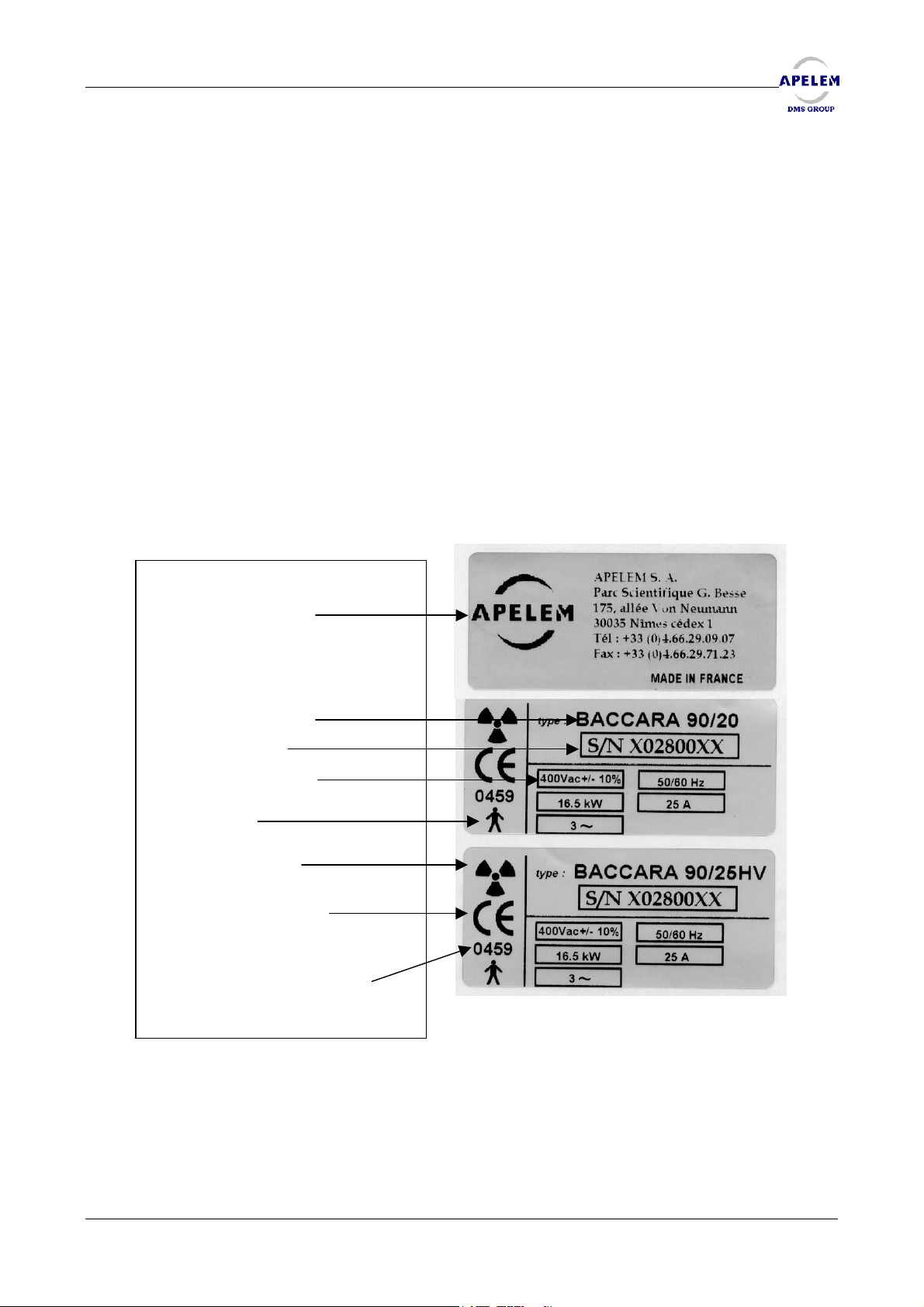
1.14. DESCRIPTION OF LABELS
Manufacturer
Name of the device
Serial number
Power supply
B Type
Ionizing radiations
CE standard according to
European Directive
93/42/CEE)
Number of the notified body
for APELEM products
User’s Manual [Doc: 80-40-002. Rev. L] 9/54
Page 10

REMOTE CONTROLLED TABLES BACCARA 90/20 & 90/25 HV
BACCARA 90/20 & 90/25 HV
BACCARA 90/20 & 90/25 HVBACCARA 90/20 & 90/25 HV
1.15. REGULATION
This device is in conformity with the IEC 60601-1 standard and belongs to II b class according
to the 93/42/CEE norm, appendix IX, regulation 10.
1.16. APELEM-DMS Group WARRANTY
The validity of DMS-APELEM is 12 months from certificate receipt date and it covers mending
or free replacement of spare parts as well as handwork (except for the unload tubes which have a
warranty in proportion to 12 months).
APELEM – DMS warranty is not valid for operations and mending caused by external factors:
- Fire, explosion, floods, subsidence of buildings,
- Default of the device relative to the environmental conditions,
- Non respect or non observance of the prescriptions given by the manufacturer in the
User’s manual,
- Operations or mending carried out by a non qualified staff and not agreed by APELEM –
DMS Group
APELEM-DMS
Parc Scientifique Georges Besse
175, allée Von Neumann
30035 NIMES CEDEX 9 - FRANCE
Tel 00 33 04 66 29 09 07
Fax 00 33 04 66 29 09 98
e-mail : [email protected]
10/ 54 [Doc: 80-40-002. Rev L.] User’s Manual
Page 11
REMOTE CONTROLLED TABLES BACCARA 90/20 & 90/25 HV
2. PRODUCT DESCRIPTION
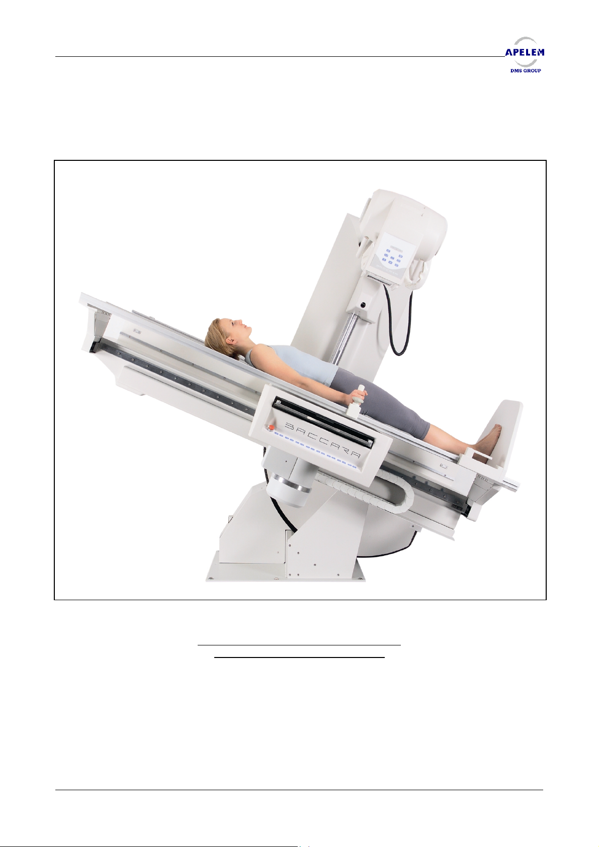
2.1. BACCARA 90/20
Remote Controlled Table BACCARA 90/20
(Elevator and tilting from 90° to 20°)
User’s Manual [Doc: 80-40-002. Rev. L] 11/54
Page 12
REMOTE CONTROLLED TABLES BACCARA 90/20 & 90/25 HV
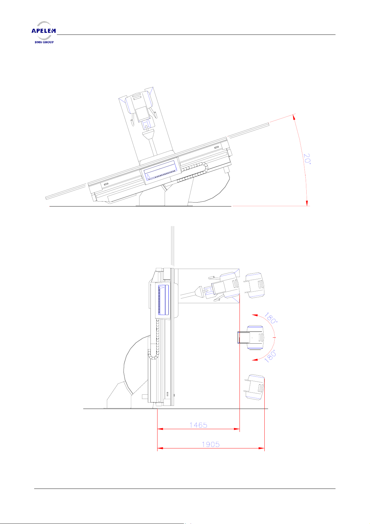
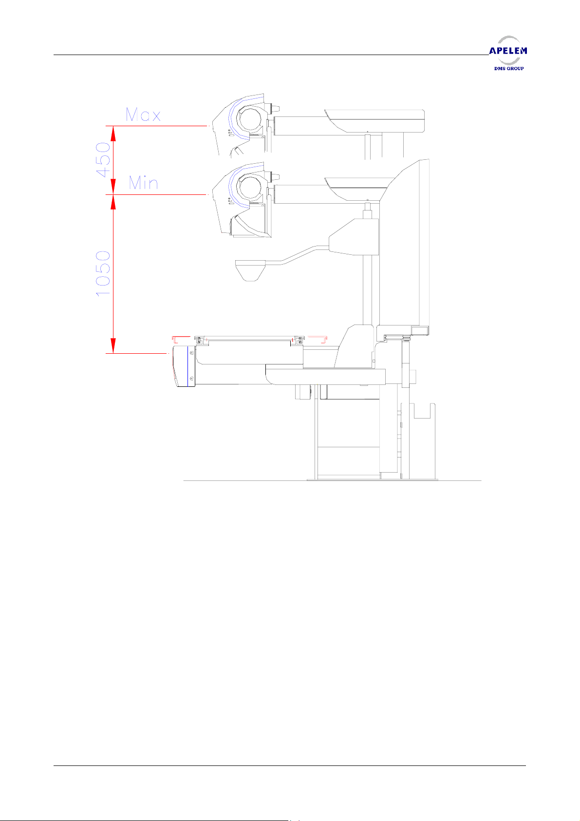
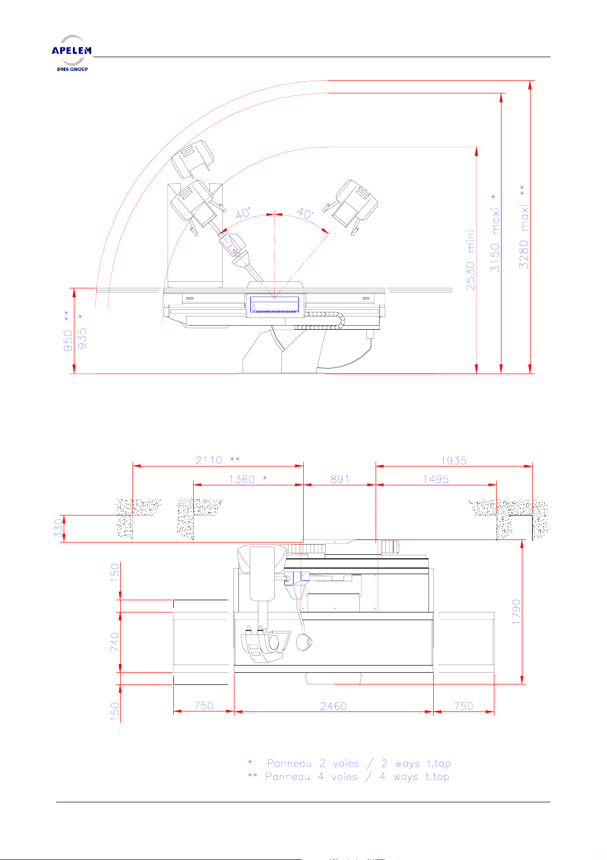
2.1.1. BACCARA 90/20 MECHANICAL DRAWINGS AND DIMENSIONS
BACCARA 90/20 & 90/25 HV
BACCARA 90/20 & 90/25 HVBACCARA 90/20 & 90/25 HV
12/ 54 [Doc: 80-40-002. Rev L.] User’s Manual
Page 13
REMOTE CONTROLLED TABLES BACCARA 90/20 & 90/25 HV
User’s Manual [Doc: 80-40-002. Rev. L] 13/54
Page 14
REMOTE CONTROLLED TABLES BACCARA 90/20 & 90/25 HV
BACCARA 90/20 & 90/25 HV
BACCARA 90/20 & 90/25 HVBACCARA 90/20 & 90/25 HV
* Panneau 2 voies / 2 ways t.top
** Panneau 4 voies / 4 ways t.top
14/ 54 [Doc: 80-40-002. Rev L.] User’s Manual
Page 15
REMOTE CONTROLLED TABLES BACCARA 90/20 & 90/25 HV
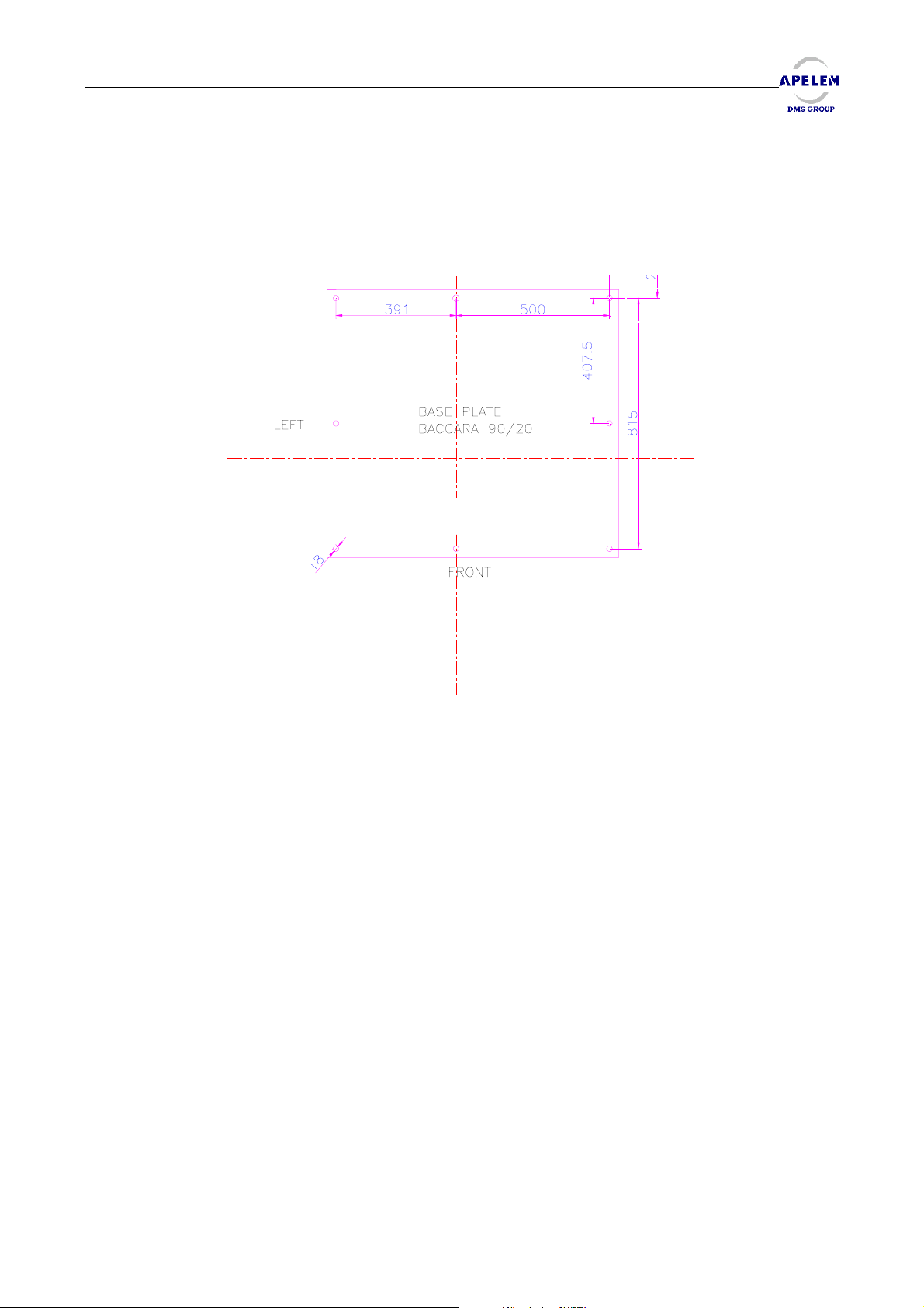
2.1.2. BACCARA 90/20 STRAIGHT SCREWED ON THE FLOOR
Before starting the table installation, check the levelness of the floor, correct it if necessary.
The table will be hold on the ground by 8 fixing points which can resist to a 1000 daN tractive effort.
User’s Manual [Doc: 80-40-002. Rev. L] 15/54
Page 16
REMOTE CONTROLLED TABLES BACCARA 90/20 & 90/25 HV
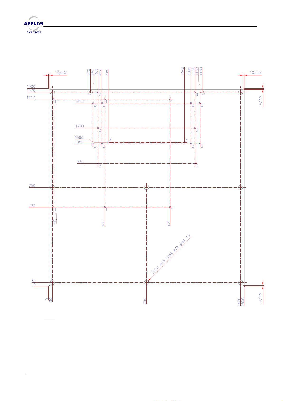
2.1.3. FASTENING THE BACCARA 90/20 WITH A DISTRIBUTION PLATE
BACCARA 90/20 & 90/25 HV
BACCARA 90/20 & 90/25 HVBACCARA 90/20 & 90/25 HV
Note
: Only the reference mark n°1 refers to the 90/20 BACCARA table mounting.
The presence of the distribution plate is only necessary in case the floor is not strong enough
to support the table.
The distribution plate will be hold on the ground by 8 fixing points, which can resist to a 1000
daN tractive effort. Then, the table will be hold on the distribution plate by 8 fixing points which can
resist to a 1000 daN tractive effort.
We remind to the user that the distribution plate is not supplied by APELEM-DMS Group.
16/ 54 [Doc: 80-40-002. Rev L.] User’s Manual
Page 17
REMOTE CONTROLLED TABLES BACCARA 90/20 & 90/25 HV
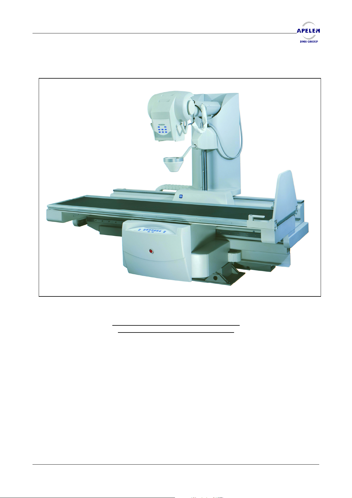
2.2. BACCARA 90/25 HV
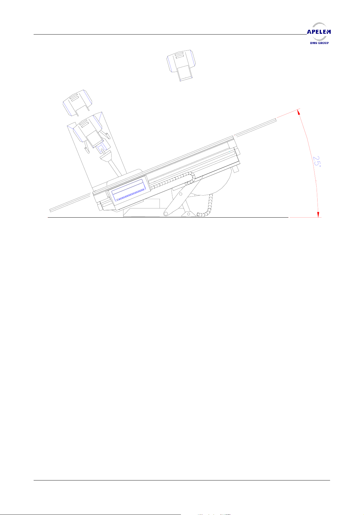
Remote Controlled Table BACCARA 90/25HV
(Variable height and tilting de 90° to 25°)
User’s Manual [Doc: 80-40-002. Rev. L] 17/54
Page 18
REMOTE CONTROLLED TABLES BACCARA 90/20 & 90/25 HV
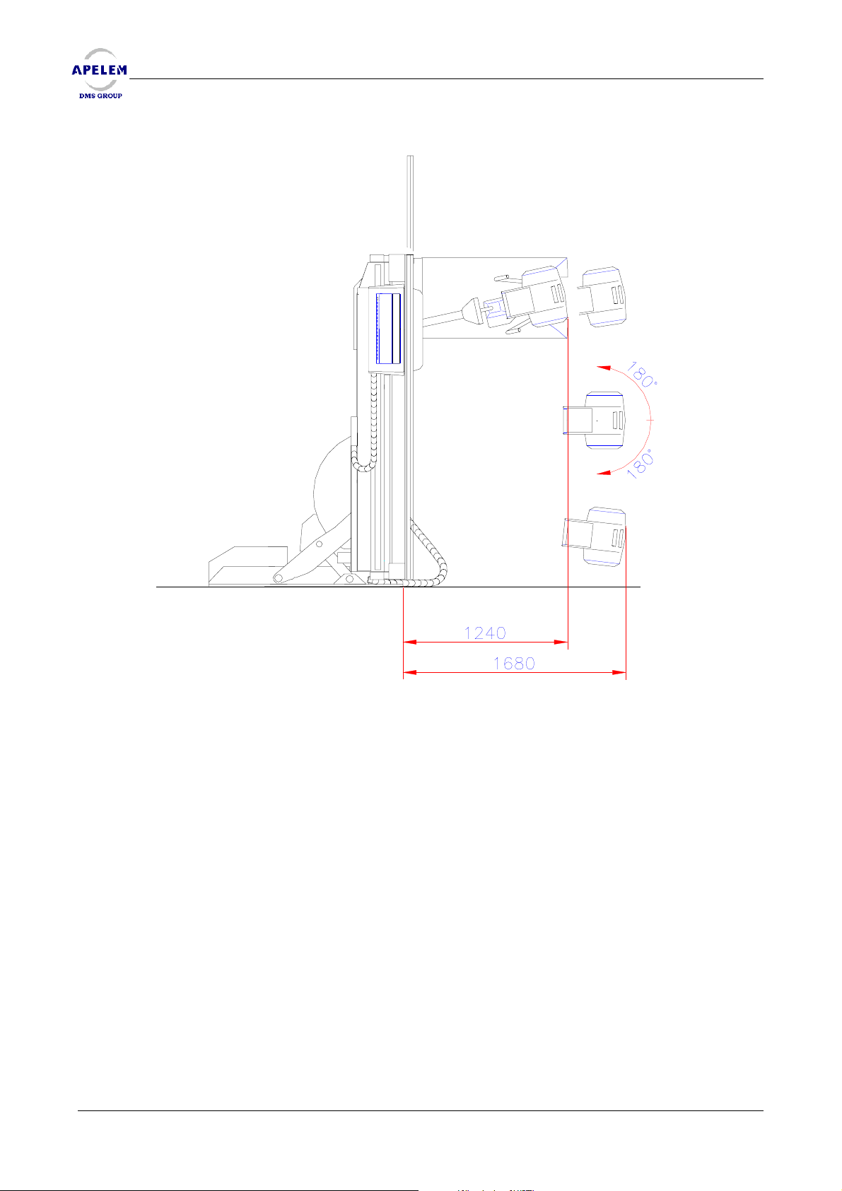
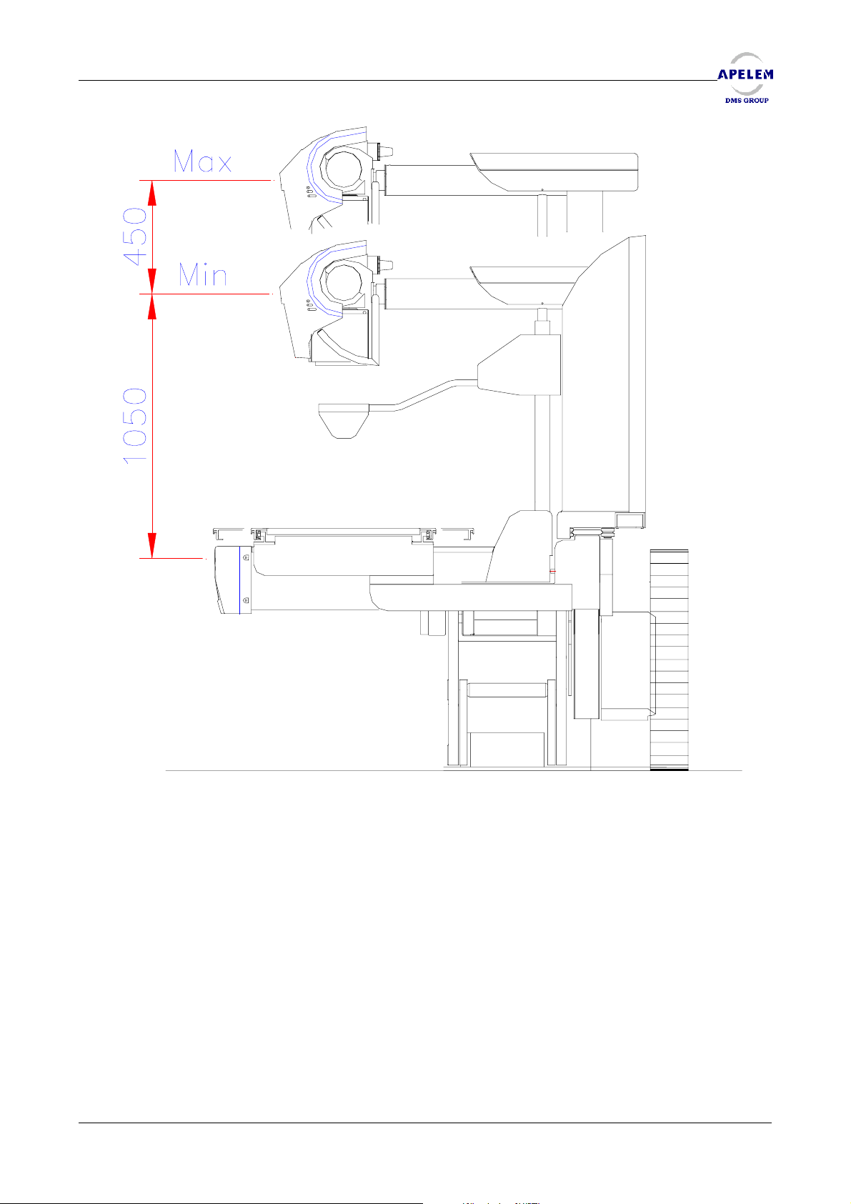
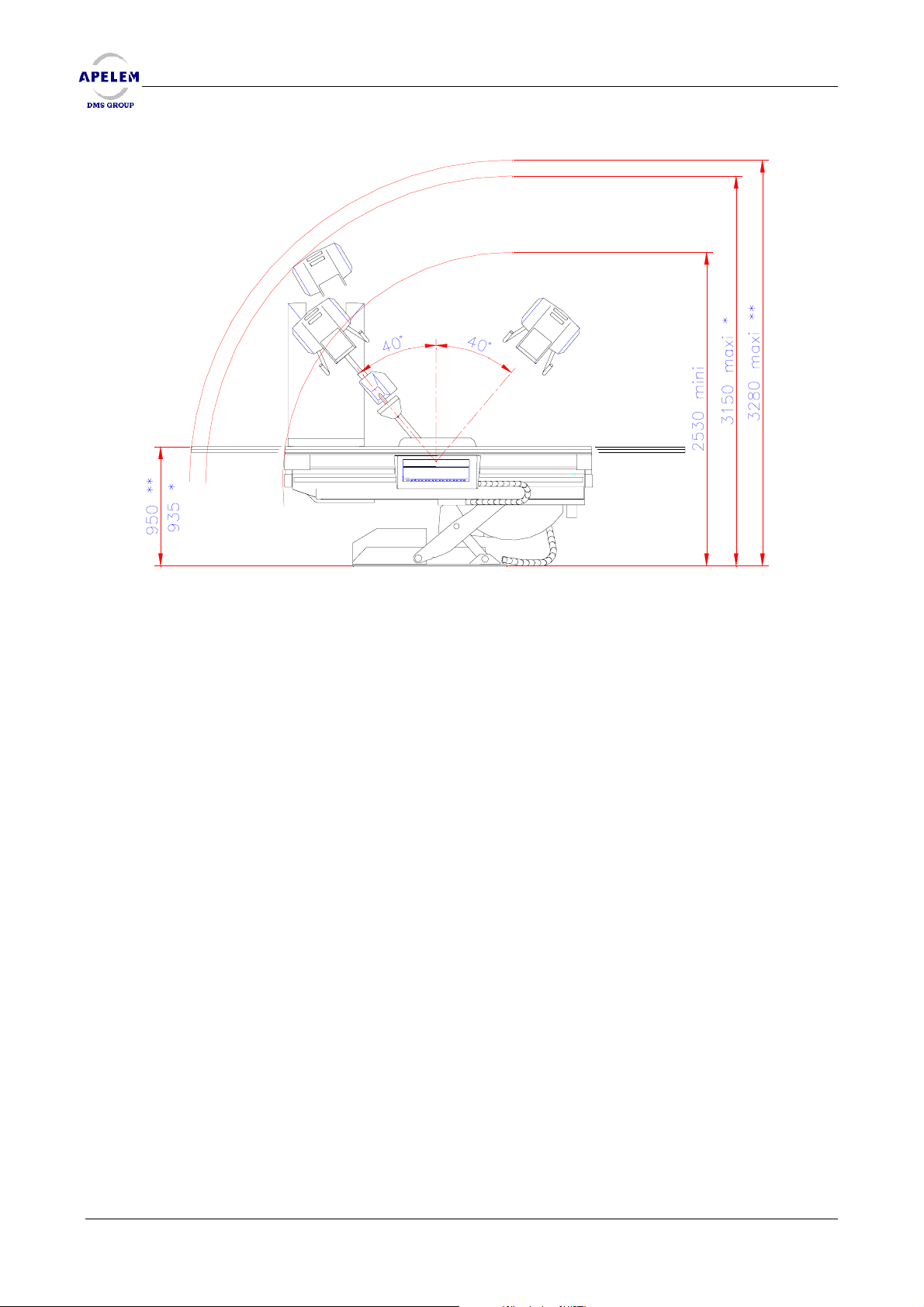
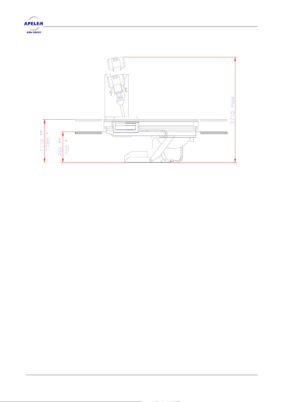
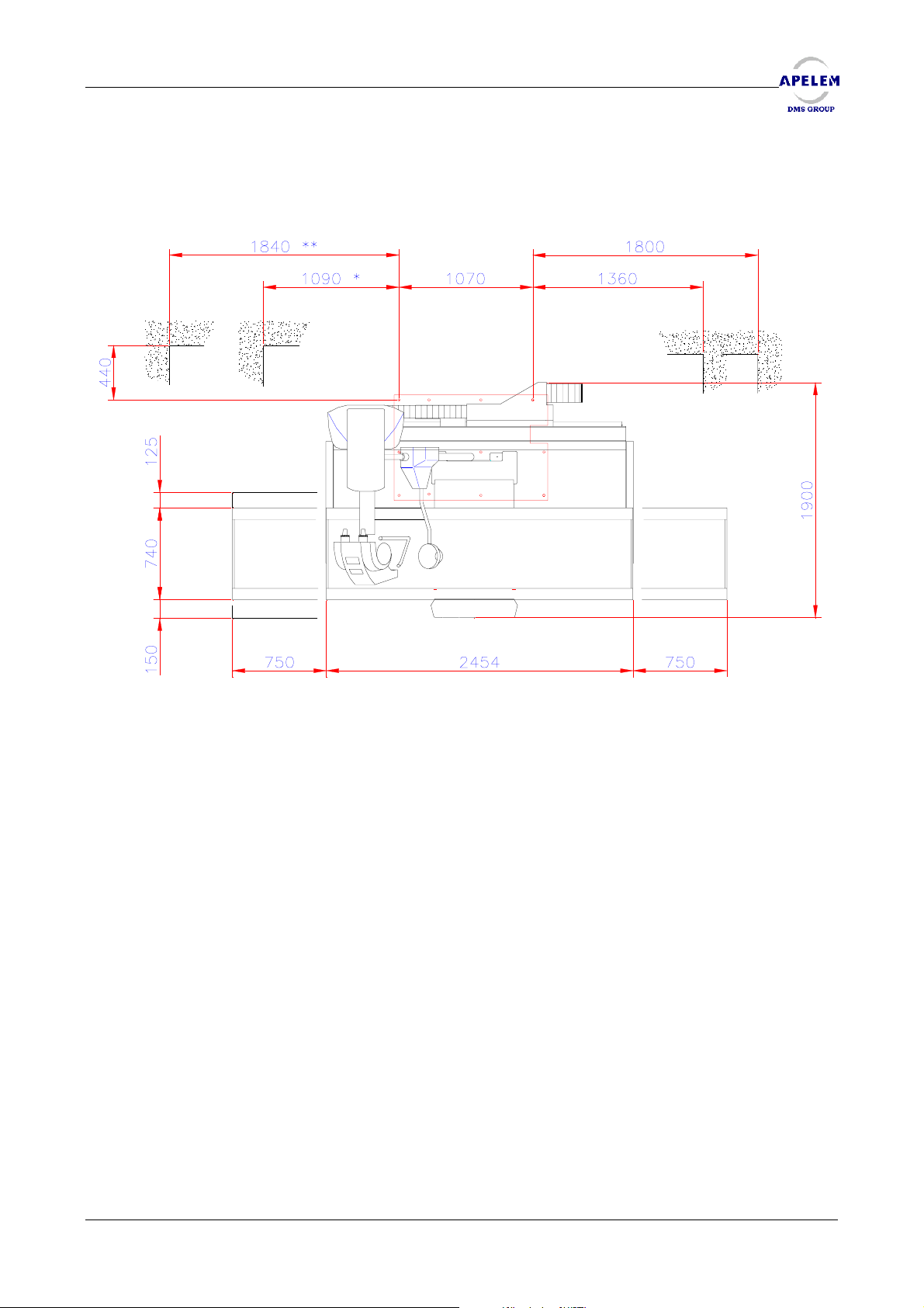
2.2.1. BACCARA 90/25 HV MECHANICAL DRAWINGS AND DIMENSIONS
BACCARA 90/20 & 90/25 HV
BACCARA 90/20 & 90/25 HVBACCARA 90/20 & 90/25 HV
18/ 54 [Doc: 80-40-002. Rev L.] User’s Manual
Page 19
REMOTE CONTROLLED TABLES BACCARA 90/20 & 90/25 HV
User’s Manual [Doc: 80-40-002. Rev. L] 19/54
Page 20
REMOTE CONTROLLED TABLES BACCARA 90/20 & 90/25 HV
BACCARA 90/20 & 90/25 HV
BACCARA 90/20 & 90/25 HVBACCARA 90/20 & 90/25 HV
* Panneau 2 voies / 2 ways t.top
** Panneau 4 voies / 4 ways t.top
20/ 54 [Doc: 80-40-002. Rev L.] User’s Manual
Page 21
REMOTE CONTROLLED TABLES BACCARA 90/20 & 90/25 HV
User’s Manual [Doc: 80-40-002. Rev. L] 21/54
Page 22
REMOTE CONTROLLED TABLES BACCARA 90/20 & 90/25 HV
BACCARA 90/20 & 90/25 HV
BACCARA 90/20 & 90/25 HVBACCARA 90/20 & 90/25 HV
* Panneau 2 voies / 2 ways t.top
** Panneau 4 voies / 4 ways t.top
22/ 54 [Doc: 80-40-002. Rev L.] User’s Manual
Page 23
REMOTE CONTROLLED TABLES BACCARA 90/20 & 90/25 HV
* Panneau 2 voies / 2 ways t.top
** Panneau 4 voies / 4 ways t.top
User’s Manual [Doc: 80-40-002. Rev. L] 23/54
Page 24

REMOTE CONTROLLED TABLES BACCARA 90/20 & 90/25 HV
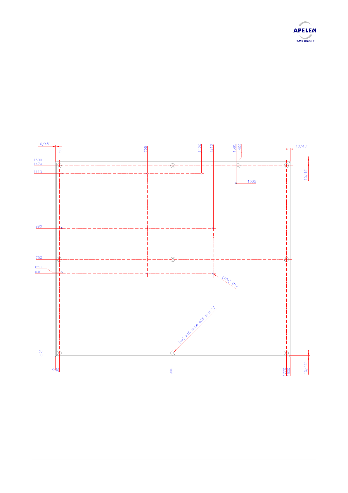
2.2.2. BACCARA 90/25 HV STRAIGHT SCREWED ON THE FLOOR
BACCARA 90/20 & 90/25 HV
BACCARA 90/20 & 90/25 HVBACCARA 90/20 & 90/25 HV
Before starting the table installation, check the levelness of the floor, correct it if necessary.
The table will be hold on the ground by 11 fixing points which can resist to a 1000 daN tractive
effort.
See Diagram N° M80 22 48 next page.
24/ 54 [Doc: 80-40-002. Rev L.] User’s Manual
Page 25
REMOTE CONTROLLED TABLES BACCARA 90/20 & 90/25 HV
2.2.3. FASTENING THE BACCARA 90/25 HV WITH A DISTRIBUTION PLATE
The presence of the distribution plate is only necessary in case the floor is not strong enough
to support the table.
The distribution plate will be hold on the ground by 10 fixing points, which can resist to a
1000 daN tractive effort. Then, the table will be hold on the base plate by 11 fixing points which can
resist to a 1000 daN tractive effort.
We remind to the user that the distribution plate is not supplied by APELEM-DMS Group.
Distribution plate
User’s Manual [Doc: 80-40-002. Rev. L] 25/54
Page 26

REMOTE CONTROLLED TABLES BACCARA 90/20 & 90/25 HV
Page intentionally left blank
BACCARA 90/20 & 90/25 HV
BACCARA 90/20 & 90/25 HVBACCARA 90/20 & 90/25 HV
26/ 54 [Doc: 80-40-002. Rev L.] User’s Manual
Page 27
REMOTE CONTROLLED TABLES BACCARA 90/20 & 90/25 HV
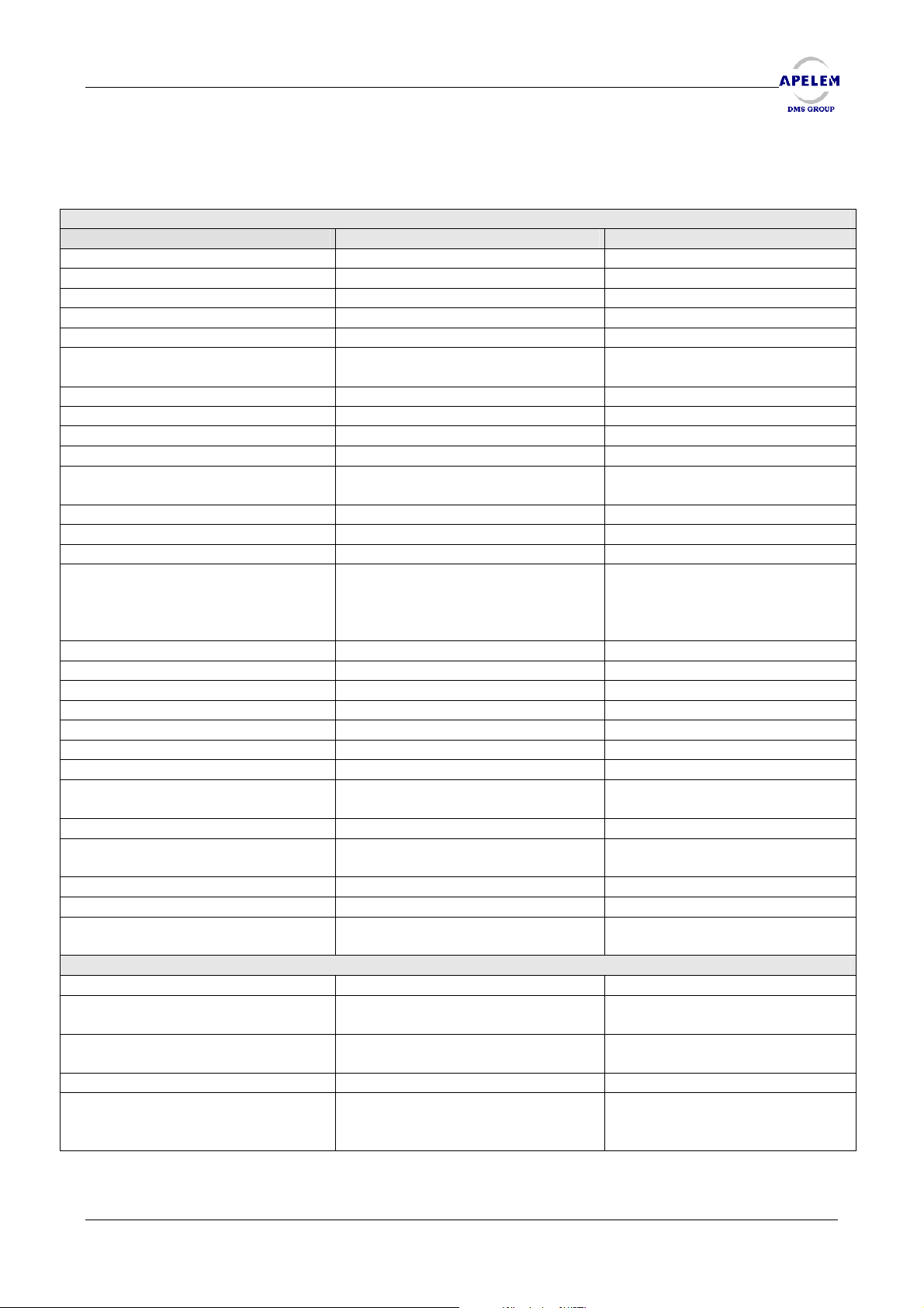
3. TECHNICAL SPECIFICATIONS
GENERAL
BACCARA 90/20 BACCARA 90/25 HV
Three phase power supply 400 V + Neutral + Earth 400 V + Neutral + Earth
Safety cut off 25 A – D curve 25 A – D curve
Average power 5 kW 5 kW
Fixed elevation 90 cm
Variable height NO 82/106 (0 ± 2cm)
Tilting -20°/+90° +90°/-20 (0,-4°) with automatic
stop at zero
Time of tilting 15,7 sec. 18 sec.
Speed of tilting 5,7°/sec. 5°/sec.
Range of column movement 1720 mm 1720 mm
Variable speed From 0 to 12 cm/sec. From 0 to 12 cm/sec.
Range of spot film device
movement
Variable speed From 0 to 12 cm/sec. From 0 to 12 cm/sec.
Range of side panel mov. 30 cm 27,5 cm
Dimensions 246 x 74 cm 246 x 74 cm
Weight Table: 950 Kg
Maximum patient weight 160 Kg 160 Kg
Type of panel Flat Flat
Speed 3,5 cm/sec. 3,5 cm/sec
Range of focal distance 105 to 150 cm 105 to 150 cm
Incidence - 40° / + 40° - 40° / + 40°
Speed 4 cm/sec. 4 cm/sec.
Parallax adjustment Yes Yes
Rotation of X-ray tube
(mechanical)
Spot film device format 18 x 24 to 36 x 43 cm 18 x 24 to 36 x 43 cm
Selection 2/3/4/5 according sizes,
Size of Image Intensifier 23/32/36/40 cm 23/32/36/40 cm
Retractable grid Yes Yes
Radiological room minimal size (L)4,10 m x (l)3 m x (H)3,35 m
Fast sequence Fast sequence
Radiography and Tomography
Remaining exposures display
Ionization chamber Ionization chamber
Grid 90L/cm
1580 mm (2 way panel)
1380 mm (4 way panel)
Cabinet: 80 Kg
Console with base: 27 Kg
Console without base : 7,9 Kg
+/-180° +/-180°
redivisible
Without limitation
AUTOMATIC SPOT FILM DEVICE
on the same film
and cassette size display
Ratio 12:1
Focal distance 120 cm
1580 mm (2 way panel)
1380 mm (4 way panel)
Table: 1500 Kg
Cabinet: 80 Kg
Console with base: 27 Kg
Console without base : 7,9 Kg
2/3/4/5 according sizes,
redivisible
(L)4,10 m x (l)3 m x (H)3,35 m
Without limitation
Radiography and
Tomography on the same film
Remaining exposures display
and cassette size display
Grid 90L/cm
Ratio 12:1
Focal distance 120 cm
User’s Manual [Doc: 80-40-002. Rev. L] 27/54
Page 28
REMOTE CONTROLLED TABLES BACCARA 90/20 & 90/25 HV
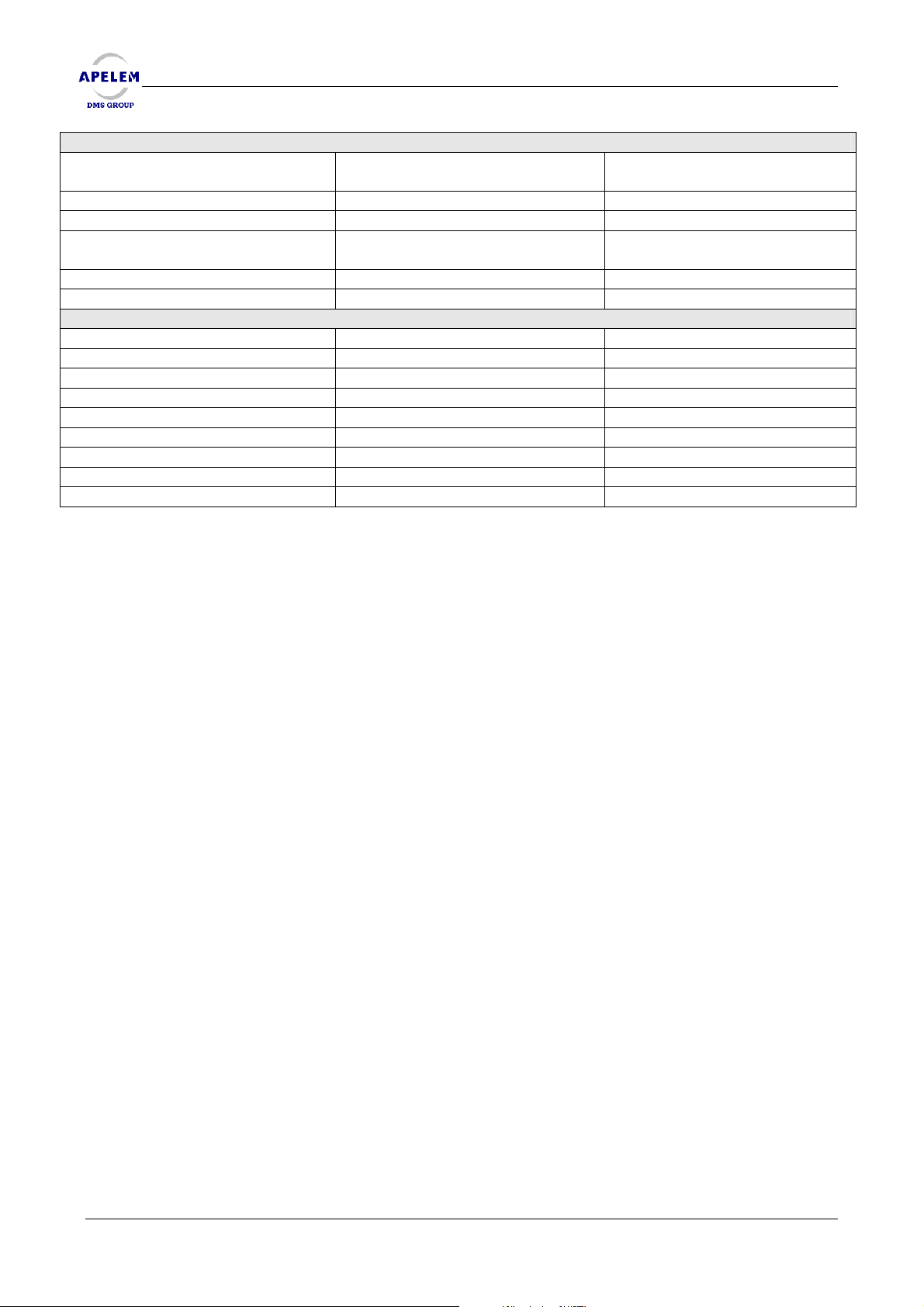
TOMOGRAPHY
Parallel tomographic plan
programmable
Focal distance 105 to 120 cm 105 to 120 cm
Angles - 8° - 20° - 40° - 8° - 20° - 40°
Exposure time Fast: 0.4/1/2 sec.
Slow: 0.8/2/4 sec.
Cutting layer 0 to 30 cm 0 to 30 cm
Step 1 mm 1 mm
OPTIONALS EXTRA
Image intensifier elevator Image intensifier elevator
Longitudinal movement of panel +/- 750 mm +/- 750 mm
Speed 6 cm / sec. 6 cm / sec.
PALADIO System PALADIO System
Stepping (step by step) Stepping (step by step)
Carbon fibre panel Carbon fibre panel
Lateral cassette support Lateral cassette support
Collimator Collimator
Gynaecological stirrups Gynaecological stirrups
BACCARA 90/20 & 90/25 HV
BACCARA 90/20 & 90/25 HVBACCARA 90/20 & 90/25 HV
Parallel tomographic plan
programmable
Fast: 0.4/1/2 sec.
Slow: 0.8/2/4 sec.
28/ 54 [Doc: 80-40-002. Rev L.] User’s Manual
Page 29
REMOTE CONTROLLED TABLES BACCARA 90/20 & 90/25 HV
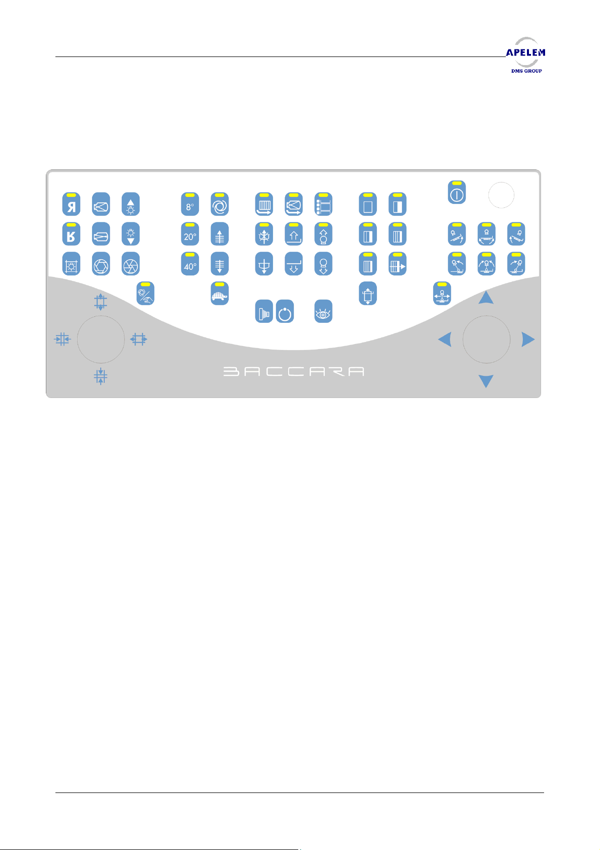
4. CONTROLS AND FUNCTIONS OF BACCARA TABLE
4.1. MAIN CONSOLE
35 37 39 28 31 18 19 20 11 12 2 1
36 38 40 29 32 21 71 23 13 14 3 4 5
41 42 43 30 33 22 72 24 15 16 6 7 8
44 34 17 9
25 26 27
45 10
1 Emergency stop
2 On/Off
3 Tilting of the table to –20° or –25°
4 Tilting of the table to horizontal
position
5 Tilting of the table to 90°
6 Tilting of the tube to –40°
7 Tilting of the tube to 0°/exit of the
Tomography mode
8 Tilting of the tube to +40°
9 Selection*
10 Movement (Transv./Longitudinal)
11 Film section 1
12 Film section 2
13 Film section 3
14 Film section 4
15 Film section 5
16 Series exposure
17 Input/Output cassette
18 Retractable grid
19 Image intensifier elevator (option)
20 Digit mode
21 Compression up
22 Compression down
23 S.I.D. Up
* Only in case of longitudinal movement option
24 S.I.D. Down
25 Graphy Control
26 Preparation control
27 Fluoroscopy control
28 8° Tomography angle
29 20° Tomography angle
30 40° Tomography angle
31 Automatic height cutting layer
32 Height cutting layer up
33 Height cutting layer down
34 Tomography low speed
35 Horizontal reverse (fluoro image)
36 Vertical reverse (fluoro image)
37 Reduction of the I.I. field
38 Increase of the I.I. field
39 Control of brightness
40 Control of brightness
41 Light centring device
42 Iris opening
43 Iris closing
44 Automatic collimator
45 Collimator shutters adjustment
71 Ascent of the table (90/25 HV)
72 Descent of the table (90/25 HV)
User’s Manual [Doc: 80-40-002. Rev. L] 29/54
Page 30
REMOTE CONTROLLED TABLES BACCARA 90/20 & 90/25 HV
BACCARA 90/20 & 90/25 HV
BACCARA 90/20 & 90/25 HVBACCARA 90/20 & 90/25 HV
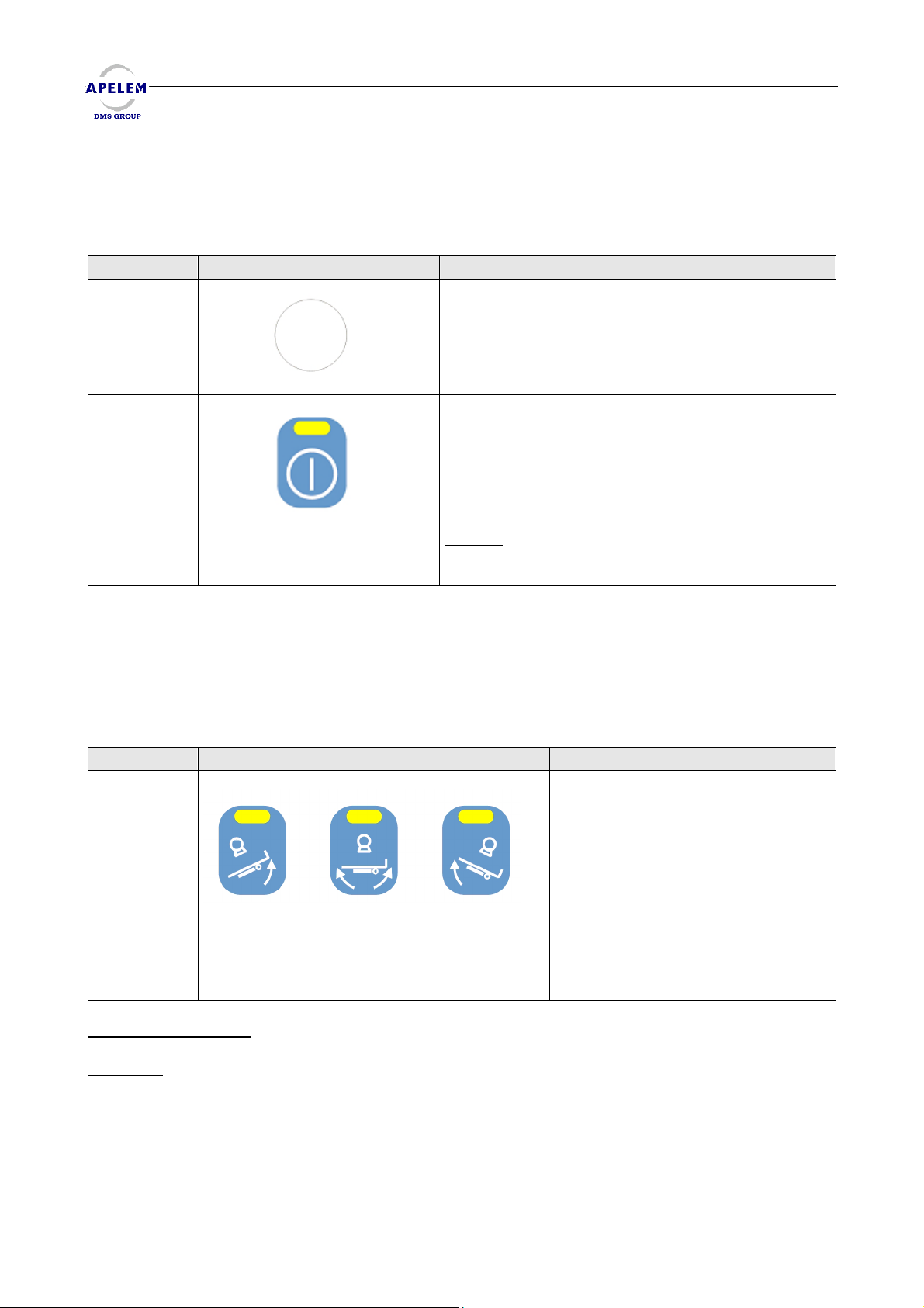
4.2. CONSOLE KEYBOARD CONTROLS
4.2.1. ON / OFF BUTTONS
KEY DESCRIPTION FUNCTION
1
2
To start up the table, check that the indicator light
Emergency switch : Stops immediately all
movements of the table.
above the key 2 is switched on and press on key 2.
If the indicator light is off, check that the
emergency stop buttons are not pushed (one on
the table console, and one on console (‘1’)and
that the power supply is ON.
Remark
table.
: Wait for 25 seconds before restarting the
4.2.2. TABLE MOVEMENTS
4.2.2.1. TILTING
KEY DESCRIPTION FUNCTION
3, 4, 5
3 4 5
Operating conditions
Warning :
fastened and that the shoulder holder is positioned. We remind to the user that the
compression band is provided with the table and that shoulder holder is optional.
When you tilt the table in trendelembourg, Check that the patient is correctly
: No stops.
3 : Allows an anticlockwise tilting of
the table to 90°.
4: Allows putting the table in the
horizontal position.
5 : Allows a clockwise tilting of the
table to – 20° or –25°.
The luminous indicators show that the
table has reached its ends of travel.
30/54 [Doc: 80-40-002. Rev.L] User’s Manual
Page 31
REMOTE CONTROLLED TABLES BACCARA 90/20 & 90/25 HV
g
g
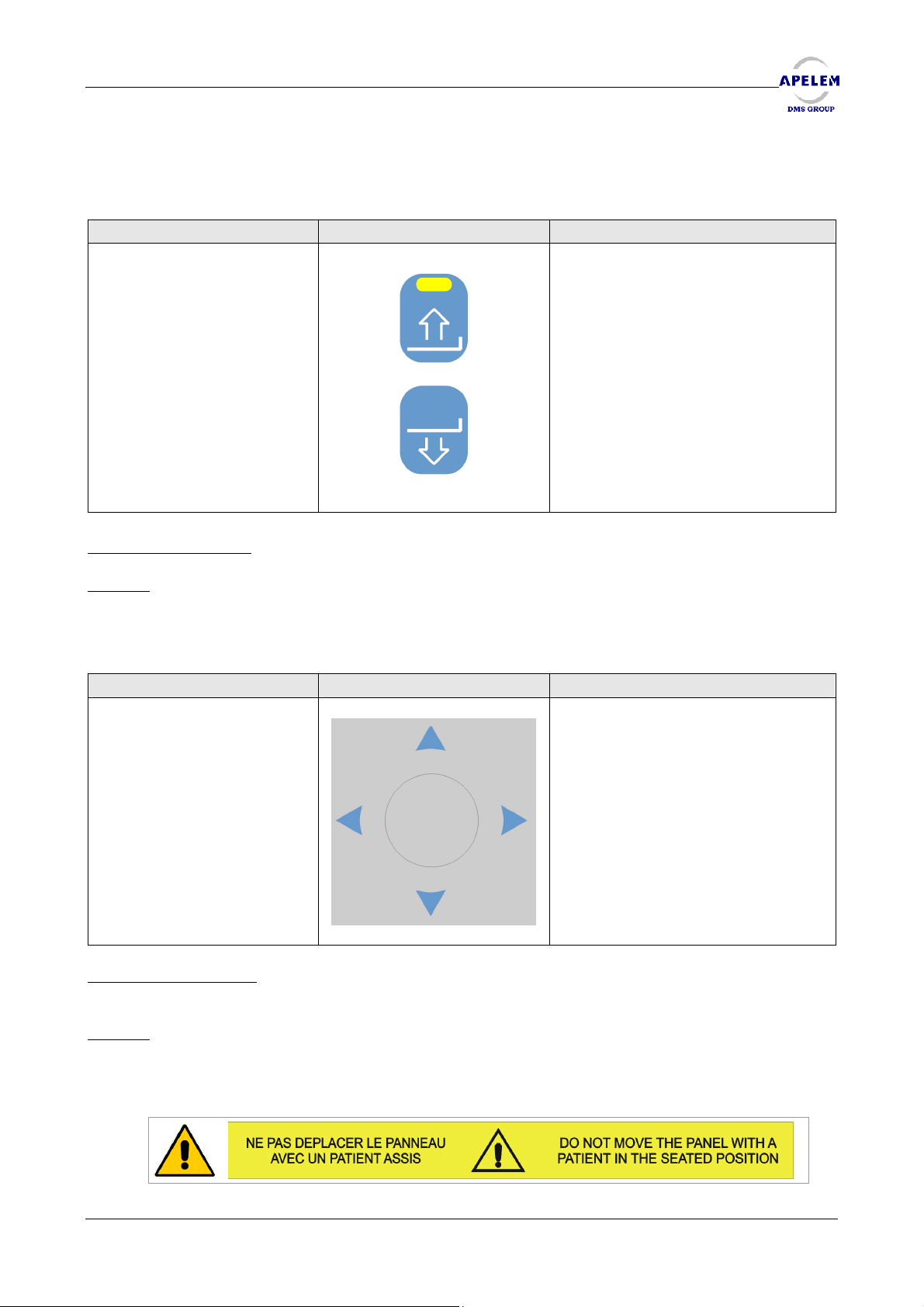
4.2.2.2. RAISING
KEY DESCRIPTION FUNCTION
71 & 72
These keys control the height of the
table and allow an elevating, or a
descending movement.
Operating conditions : Depends on ground and ceiling forbidding.
Remark
: Only with the 90/25 HV version.
4.2.2.3. SPOT FILM DEVICE CARRIAGE
KEY DESCRIPTION FUNCTION
10
Operating conditions
speed proportional to the tilt of the joystick.
Remark
Demo : The movement of the table is equal to the movement of the joystick, top view.
Normal : The image on the TV monitor follows the joystick. The inversion cameras are
connected to this mechanism according to the parameters.
: In configuration, two operating modes are available, Demo or Normal :
: The movements of the trolley or longitudinal panel have a variable
Allows the lateral movement of the
panel.
In case of lon
it allows the lon
of the trolley.
itudinal panel option,
itudinal movement
User’s Manual [Doc: 80-40-002. Rev. L] 31/54
Page 32
REMOTE CONTROLLED TABLES BACCARA 90/20 & 90/25 HV
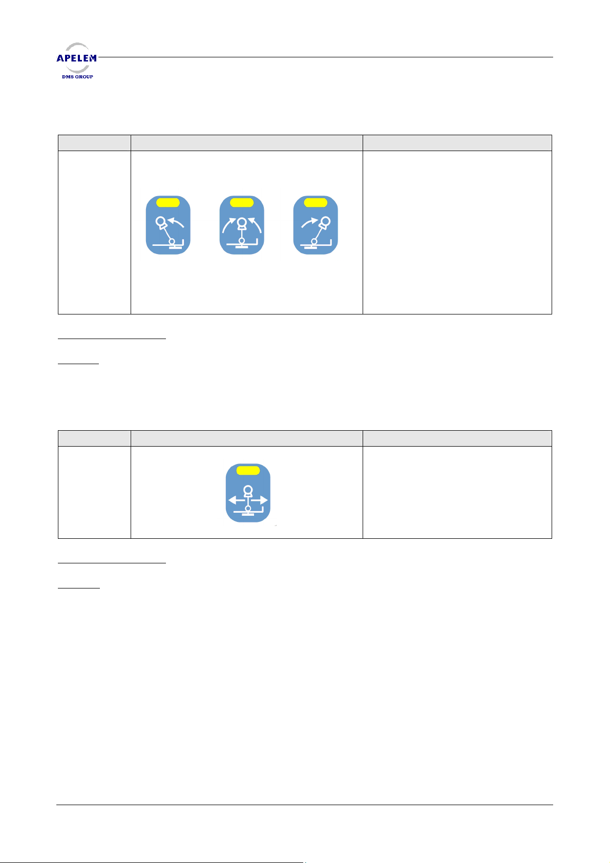
4.2.2.4. COLUMN
BACCARA 90/20 & 90/25 HV
BACCARA 90/20 & 90/25 HVBACCARA 90/20 & 90/25 HV
KEY DESCRIPTION FUNCTION
6, 7 & 8
6 7 8
Operating conditions
Remark
: The key 7 allows to exit from the tomography mode.
: No stops, and compression in parking position.
6 : Allow an anticlockwise tilting of
the column until – 40°.
7 : Allow to position the column in
vertical position at 0°.
8 : Allow a Clockwise tilting of the
column until + 40°.
The lights above indicate that the
column has reached its ends of
travel.
4.2.2.5. SPOT FILM DEVICE AND COLUMN COMBINED
KEY DESCRIPTION FUNCTION
Allows to commute the joystick 10
between the carriage and the
longitudinal panel. The light
indicates the validation of the
carriage movement with the switch
10.
9
Operating conditions
Remark
stays on.
: If the table has not the longitudinal panel option, this key is inactive and the light
: Presence of the four ways panel option
32/54 [Doc: 80-40-002. Rev.L] User’s Manual
Page 33
REMOTE CONTROLLED TABLES BACCARA 90/20 & 90/25 HV
4.2.3. USE OF ELEMENTS
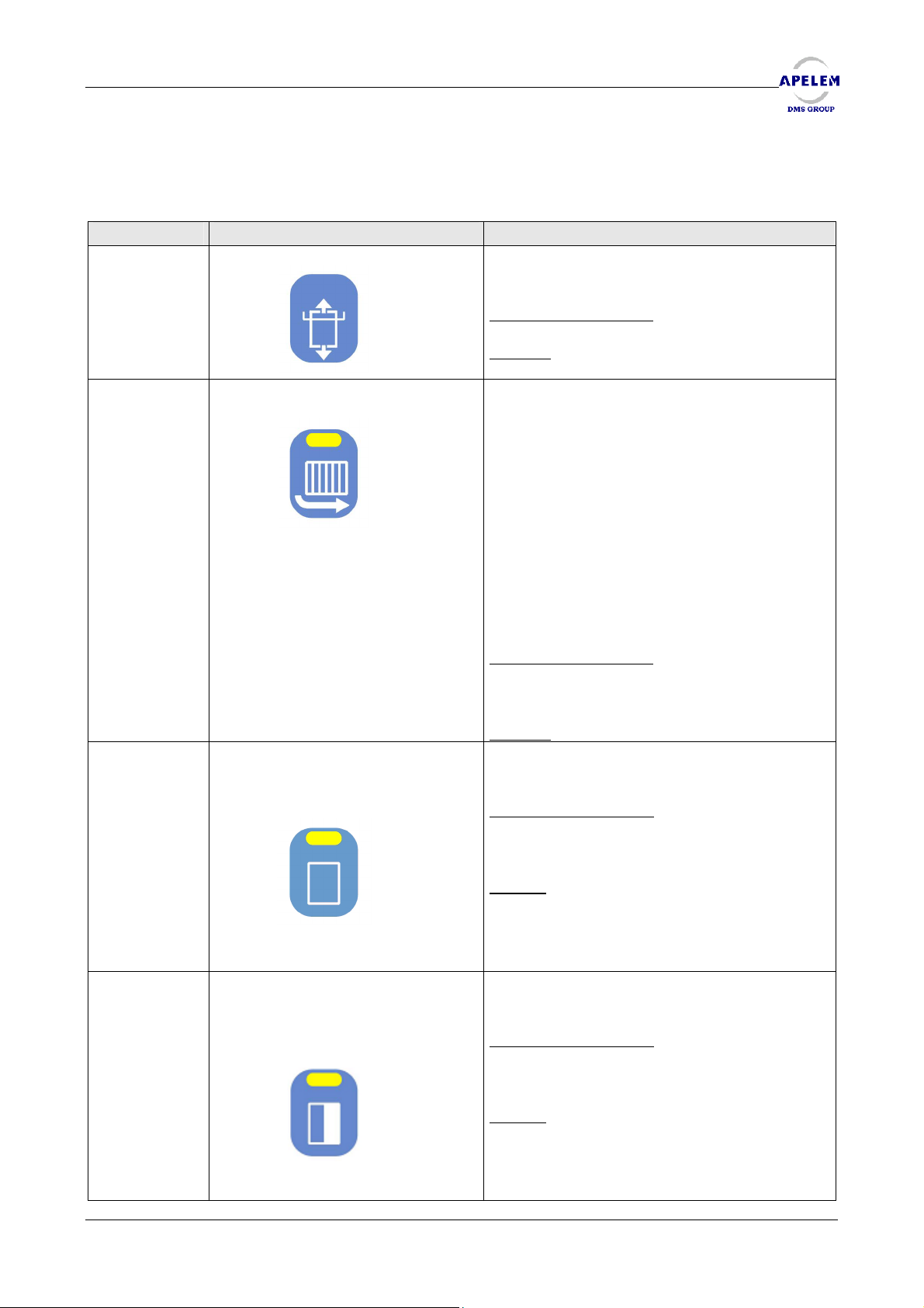
4.2.3.1. SPOT FILM DEVICE
KEY DESCRIPTION FUNCTION
17
18
11
12
Allows to push the cassette holder in and
out.
Operating conditions
: None
Remark
: Any power control must be
activated. The tube must be centered.
If the key 18 is voluntarily activated, the grid
will retract itself from the X-ray field.
- When the led flashes on the grid will
retract. If the flashing is continuing in spite of
the stop of the movement, there is a
problem on the grid functioning.
- If the led is switched off, the grid is in
position.
- If the led is switched on, the grid is
rectracted.
Operating conditions
: The retraction must
be validated in the configuration mode
(parameter 204).
Remark
: None
Allows to choose the cutting of the film
according to the respective indicators.
Operating conditions
: Cutting of 8cm mini
and therefore possible choice of cutting
according to the cassette size.
Remark: It should be noted that the sections
are selected on the remaining surface of the
film. Therefore, it is possible to re divided a
film in 1, 2, 3, or 4 according to the remaining
area.
Allows to choose the cutting of the film
according to the respective indicators.
Operating conditions
: Cutting of 8cm mini
and therefore possible choice of cutting
according to the cassette size.
Remark
: It should be noted that the sections
are selected on the remaining surface of the
film.
Therefore, it is possible to re divided a film in
1, 2, 3, or 4 according to the remaining area.
User’s Manual [Doc: 80-40-002. Rev. L] 33/54
Page 34
REMOTE CONTROLLED TABLES BACCARA 90/20 & 90/25 HV
BACCARA 90/20 & 90/25 HV
BACCARA 90/20 & 90/25 HVBACCARA 90/20 & 90/25 HV
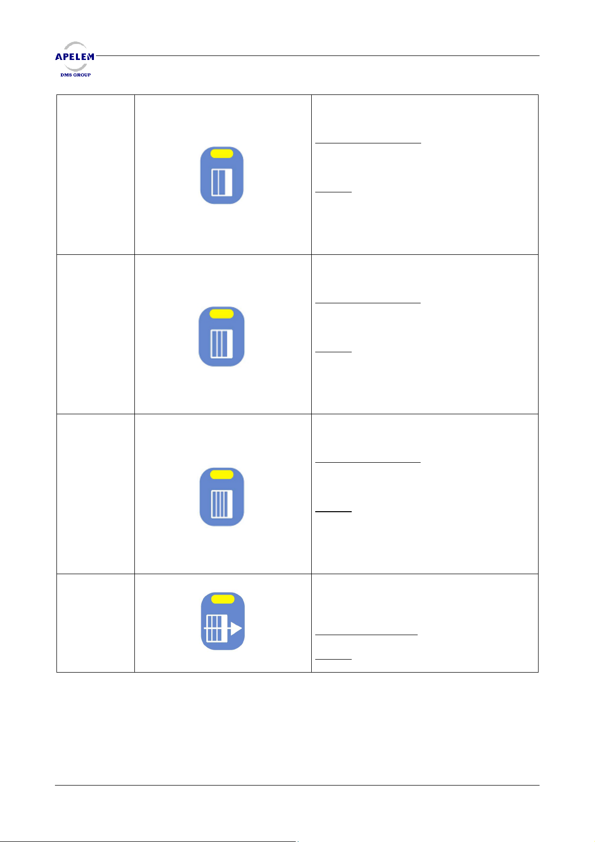
13
14
15
16
Allows to choose the cutting of the film
according to the respective indicators.
Operating conditions
and therefore possible choice of cutting
according to the cassette size.
Remark
are selected on the remaining surface of
the film. Therefore, it is possible to re divided
a film in 1, 2, 3, or 4 according to the
remaining area.
Allows to choose the cutting of the film
according to the respective indicators.
Operating conditions
and therefore possible choice of cutting
according to the cassette size.
Remark
are selected on the remaining surface of
the film. Therefore, it is possible to re divided
a film in 1, 2, 3, or 4 according to the
remaining area.
Allows to choose the cutting of the film
according to the respective indicators.
Operating conditions
and therefore possible choice of cutting
according to the cassette size.
Remark
are selected on the remaining surface of
the film. Therefore, it is possible to re divided
a film in 1, 2, 3, or 4 according to the
remaining area.
Allows a serial exposure that is to say that
you don’t have to release the graphy
button 25 to take an exposure.
Operating conditions
Remark
: It should be noted that the sections
: It should be noted that the sections
: It should be noted that the sections
: None.
: Cutting of 8cm mini
: Cutting of 8cm mini
: Cutting of 8cm mini
: None
34/54 [Doc: 80-40-002. Rev.L] User’s Manual
Page 35
REMOTE CONTROLLED TABLES BACCARA 90/20 & 90/25 HV
4.2.3.2. FOCAL
KEY DESCRIPTION FUNCTION
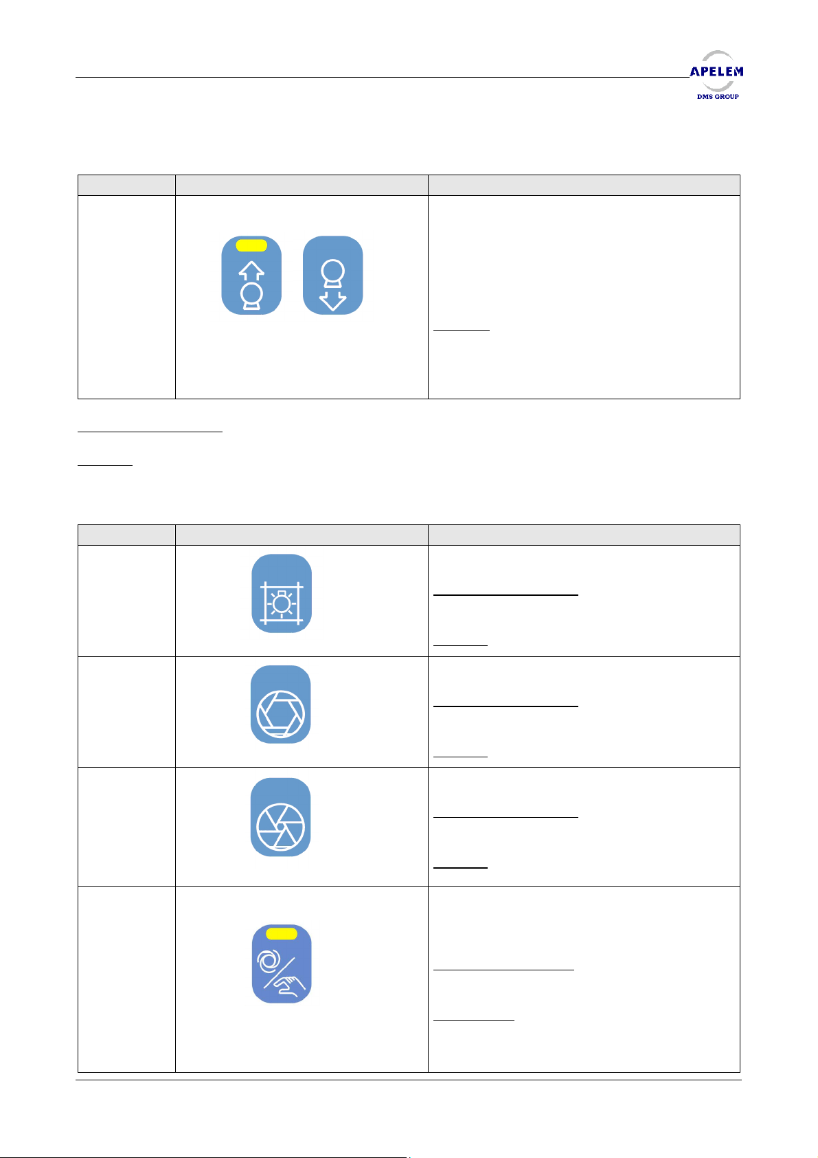
23 & 24
Operating conditions
Remark
: Tomography prohibited beyond 120 cm.
23 24
: Depend on the ceiling forbidding.
These keys control the focal distance.
The key 23 allows the elevating movement
of the tube.
The key 24 allows the descending
movement of the tube.
Remark
of the tube has an influence on the
incidence of the column and on the
tomography too.
: It should be noted that the height
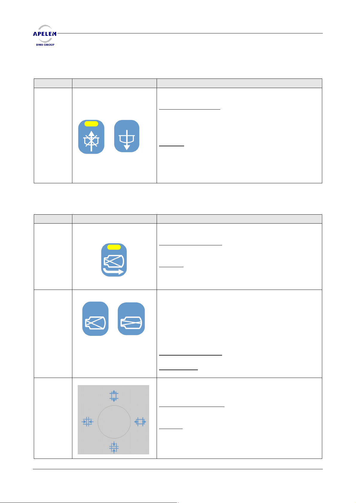
4.2.3.3. COLLIMATOR & CENTERING DEVICE
KEY DESCRIPTION FUNCTION
The key 41 is used for switching on the light
centering device.
41
42
43
44
Operating conditions
parameter mode for timer temporizing.
Remark
Controls the collimator iris opening.
Operating conditions
be in manual mode.
Remark
Controls the collimator iris closing.
Operating conditions
be in manual mode.
Remark
Allows the collimator to enter in the
automatic or in the manual mode.
(Led switched on = automatic)
Operating conditions
centered.
Observation
tube or the direct position of
the generator will position the collimator into
the manual mode.
: None
: None
: None
: The switch of the off-centre
: Enter a value in the
: The collimator must
: The collimator must
: The tube must be
User’s Manual [Doc: 80-40-002. Rev. L] 35/54
Page 36
REMOTE CONTROLLED TABLES BACCARA 90/20 & 90/25 HV
4.2.3.4. COMPRESSION
BACCARA 90/20 & 90/25 HV
BACCARA 90/20 & 90/25 HVBACCARA 90/20 & 90/25 HV
KEY DESCRIPTION FUNCTION
21 & 22
21 22
4.2.3.5. USE OF THE IMAGE INTENSIFIER
These keys control the compression.
Operating conditions
compression can be brought to its lowest position,
while if the column is tilted, the compressor travel is
limited.
Remark :
compression is in pressure on the patient, both column
and panel movements are prohibited in order to
protect the patient. (A message is displayed in case a
prohibited movement request and the led of upper
compressor end of travel begins to flash).
It should be noted that as soon as the
: In centered position, the
KEY DESCRIPTION FUNCTION
37 & 38
19
45
37 38
Controls the height of the image intensifier (option).
Operating conditions
the cassette holder is in the parking position.
Remark
mode film, the Image intensifier immediately returns in
the upper position. This key operates only with the
elevator image intensifier option.
These keys control the image intensifier magnification.
The key 37 reduces the I.I. field and the image is
enlarged.
The key 38 increases the I.I. field and the image is
reduced.
Operating conditions
Observation
intensifier magnification has been defined.
Controls the opening and the closing of the collimator
shutters.
Operating conditions
manual mode.
Remark
: as soon as the fluoroscopy is pressed in the
: Keys are validated only if the image
: None.
: The image intensifier rises only if
: None
: The collimator must be in the
36/54 [Doc: 80-40-002. Rev.L] User’s Manual
Page 37
REMOTE CONTROLLED TABLES BACCARA 90/20 & 90/25 HV
4.2.3.6.TOMOGRAPHY MODE
• Precautionary measures:
The description which follows concerning the use of tomography supposes that the interface tablegenerator-digital system has been correctly realized and tested.
• Display:
Film : --- X --- Division : - / -
Angle tomo : 8° Time : Ø 50 / 1s
Layer : 0 mm Auto step : 0 mm
Tomo : Ready Speed : Fast or slow
Film : indicates the film size.
Angle tomo : User’s choice (8°, 20°, 40°). Indicates the scanning angle of X-rays.
Layer : corresponds to the tomo cutting layer. The number in mm indicates the distance in height of
the patient body in comparison with the table top.
Tomo : indicates that the tomography is ready.
Division : indicates the current number of cuttings according to the size of the film. Between 1 and
5.
Time : The time automatically displays according to the chosen tomo angle.
Two speeds are available :
- 0, 50s = fast.
- 1 sec = slow and may be set using the turtle key.
Auto step : corresponds to the automatic incrementation in mm of the cutting layer.
Speed : corresponds to the current scanning speed fast or slow.
• Warning messages
MESSAGES INSTRUCTIONS NOT OBSERVED SUGGESTIONS
“Column off centre” Column not centred Center the column
Using the joystick, move lateraly
the carriage until the warning
message disappear.
“ Carriage out of position”
The travel is insufficient to
perform the tomography
User’s Manual [Doc: 80-40-002. Rev. L] 37/54
Page 38
REMOTE CONTROLLED TABLES BACCARA 90/20 & 90/25 HV
• Keys
BACCARA 90/20 & 90/25 HV
BACCARA 90/20 & 90/25 HVBACCARA 90/20 & 90/25 HV
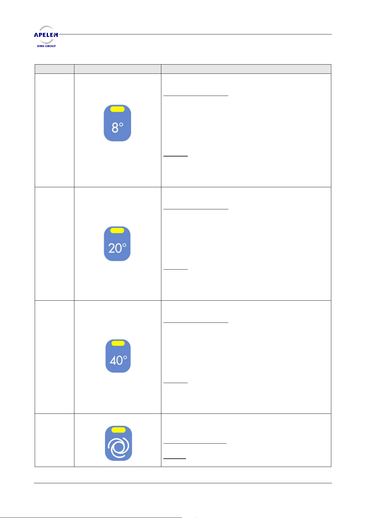
KEY DESCRIPTION FUNCTION
28
29
30
31
Allows to choose the tomography angle desired.
Operating conditions
prepare the column ; the start of the tomography will
be effective by pressing the graphy key 25.
To exit from the tomography mode, just press the key 7
center – column.
After each tomography, the column automatically
refocuses for allowing the change of cassette.
Remark
focal height does not allow the tomography in the
chosen angle, the indicator flashes and a message
displays. (Re centre the column and bring back the
carriage in the tomography range,...)
Allows to choose the tomography angle desired.
Operating conditions
prepare the column ; the start of the tomography will
be effective by pressing the graphy key 25.
To exit from the tomography mode, just press the key 7
center – column.
After each tomography, the column automatically
refocuses for allowing the change of cassette.
Remark
focal height does not allow the tomography in the
chosen angle, the indicator flashes and a message
displays. (Re centre the column and bring back the
carriage in the tomography range,...)
Allows to choose the tomography angle desired.
Operating conditions
prepare the column ; the start of the tomography will
be effective by pressing the graphy key 25.
To exit from the tomography mode, just press the key 7
center – column.
After each tomography, the column automatically
refocuses for allowing the change of cassette.
Remark
focal height does not allow the tomography in the
chosen angle, the indicator flashes and a message
displays. (Re centre the column and bring back the
carriage in the tomography range,...)
Allows the automatic progression of the cutting layer if
this function is activated (indicator switched on).
Operating conditions
Remark
height of the progression.
: If the position of the column trolley or the
: If the position of the column trolley or the
: If the position of the column trolley or the
: In this case, keys 32 & 33 allow choosing the
: Pressing the key 26 allows to
: Pressing the key 26 allows to
: Pressing the key 26 allows to
: None
38/54 [Doc: 80-40-002. Rev.L] User’s Manual
Page 39
REMOTE CONTROLLED TABLES BACCARA 90/20 & 90/25 HV
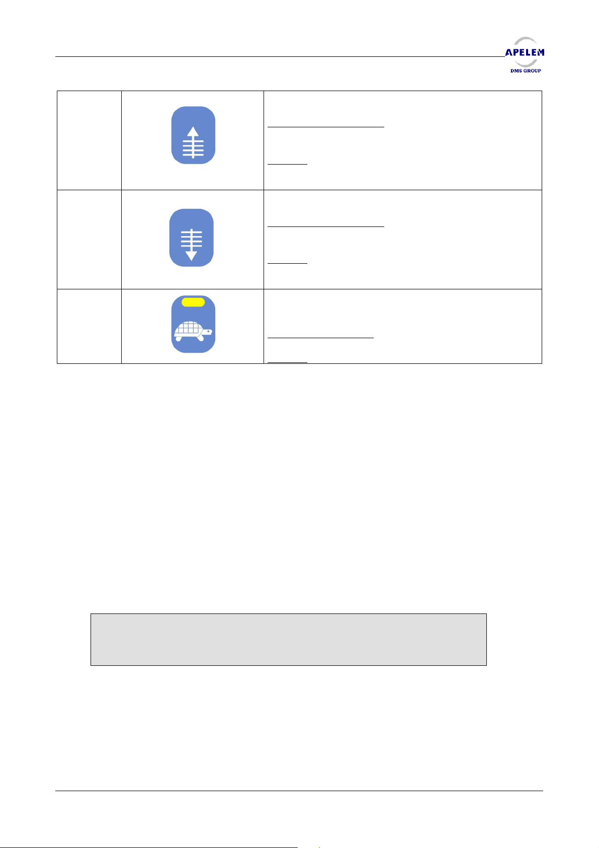
32
33
34
Allows to select the height of the cutting layer.
Operating conditions
centered and is in the Tomography mode.
Remark
layer cut (see key 31), the keys 32 & 33 select the
height of the step.
Allows to select the height of the cutting layer.
Operating conditions
centered and is in the Tomography mode.
Remark
layer cut (see key 31), the keys 32 & 33 select the
height of the step.
Selects the scanning speed. (indicator switched on =
slow speed selected).
Operating conditions
Remark
: with the automatic progression mode of the
: with the automatic progression mode of the
: None.
: Active only if the tube is
: Active only if the tube is
: None.
4.2.3.7 STEPPING MODE
The description which follows concerning the use of stepping supposes that the interface
table-generator-digital system have been correctly realized and tested. Those tests include among
others the simulation of the different stages during a stepping test upon X-ray emission with a
leaded rule.
The number of the steps and the distance to cover are chosen when the table is set and
cannot be modified in normal use. Those parameters are determined by the user, collaborating
with the fitter, and must be validated by testing without a patient but with a leaded rule according
to the exposures provided by the laser copy. They are captured in the programming mode.
Displays
When the table is informed by the generator that the stepping mode is in progress, the
screen of the table console displays specific information to this kind of examination (as
tomography).
Stepping : arterio Current step : 1 / 4
Acquisition : masks Step length : 20 cm
Field : 40 cm Coverage : 80 cm
Message area
NB: The texts in bold type are given as examples
Stepping : shows the way of discharge of the contrast product and so the movements of
the column .
« arterio » for the way from the pelvis down to feet (in the right direction of the table),
« phlebo » for the way from feet up to the pelvis ( in the left direction of the table).
User’s Manual [Doc: 80-40-002. Rev. L] 39/54
Page 40
REMOTE CONTROLLED TABLES BACCARA 90/20 & 90/25 HV
Acquisition : indicates if you are in the acquisition mode of masks or in angiography mode.
Field : indicates the intensifier field selected in cm.
Current step : indicates the number of the current steps following by the total number of
steps.
Step length : indicates the displacement distance in cm of the group base-column for one
step.
Coverage : indicates the total of the travels (not the distance realized by the X-rays).
Messages area : area reserved to error messages, signals or various (see the following
paragraphs).
Signals messages
Before starting an acquisition cycle or a test cycle with movements, the table checks that
the configuration is correct and that it will permit to execute the cycle in its totality.
Signal messages on the line in the low part of the LCD screen inform the user on conditions
which are not observed . Those messages begin by “WARNING”.
The board on the next page details the list of the different messages :
MESSAGES INSTRUCTIONS NOT OBSERVED SUGGESTIONS
“Warning: not enough travel!” The base of the spot film
device will not be able to
execute the displayed travel
(and recorded in the 722
parameter)
“Warning: table with tilting!” During the examination the
table must be in horizontal
position.
“Warning: too much focal!” During the examination the
focal is limited to 120 cm
“Warning: column not
centred!”
“Warning: I.I. field lower than
30!”
“Warning: Compression
engaged!”
The column must be centred
compared with the spot film
device.
The field of the I.I. must be
superior or equal to 30.
The compression must be in
parking position.
Move the group basecolumn, base-spot film device
to the left (arterio) or to the
right (phlebo) with the joystick
in order to allow the table to
execute the travel indicated
by the display.
Use the key which allows the
centring of the tilting on the
main board, or the two keys
of tilting (simultaneously) of
the control board.
Use the key of the focal
downstroke on the main
board.
Use the key of the column
centring on the main board.
Use the key for increasing the
I.I. field on the main board.
Use the key for ascending the
compression on the main
board.
BACCARA 90/20 & 90/25 HV
BACCARA 90/20 & 90/25 HVBACCARA 90/20 & 90/25 HV
40/54 [Doc: 80-40-002. Rev.L] User’s Manual
Page 41
REMOTE CONTROLLED TABLES BACCARA 90/20 & 90/25 HV
Error messages
These messages indicate that a problem has happened during the cycle. They begin by the
word “error”. In all cases, the stepping is stopped, and any movement is authorized. To go out of
this position, you have to select an other post than “stepping” on the generator or to re-initialize.
ERROR MESSAGES DESCRIPTION OF THE ERROR SUGGESTIONS
“Error : initialization of
inverter!”
“Error : no image intensifier!” Missing of the image
“Error : wrong stepping
parameters!”
“Error : right end of travel
reached!”
“Error : Left end of travel
reached!”
Various messages
MESSAGES DESCRIPTION SUGGESTIONS
“Ok stepping” Displays at the beginning of
“Stepping. Turtle key = store
start position”
“Turtle key = back to start step
0”
The control software unit
cannot communicate with
the inverter of the column
trolley
intensifier or parameter
indicating its presence
misinformed.
Parameters of stepping at 0
(number of steps and
distance to be covered).
The column trolley or the spot
film device trolley has
reached the right software
stop.
The column trolley or the spot
film device trolley has
reached the left software
stop.
the examination after
memorizing the start position
in order to indicate that all
conditions are right and that
the table is ready.
In normal stepping mode,
asks to position the table and
then to press on the turtle key
to memorize the position of
the start of the stepping.
Indicates that it is possible to
return to the start position
memorized by pressing the
turtle key
Contact the after sales
service ‘check the
connecting and parameters
of the frequency converter).
No stepping without
intensifier! Please contact
your retailer.
Enter in the configuration
mode (switch on board inside
the keyboard) and set the
parameters 721 and 722.
You have to quit the stepping
mode and start again from
the beginning. If the extra
travel is reached, contact
your Technical service.
You have to quit the stepping
mode and start again form
the beginning. If the extra
travel is reached, contact
your Technical service.
After an exposure in the
radiography mode, the group
column-spot film device
move on the next step.
Position the table. Press on the
turtle key.
Press on the turtle key until the
stop of movements of the
column trolley and the spot
film device trolley.
User’s Manual [Doc: 80-40-002. Rev. L] 41/54
Page 42
REMOTE CONTROLLED TABLES BACCARA 90/20 & 90/25 HV
BACCARA 90/20 & 90/25 HV
BACCARA 90/20 & 90/25 HVBACCARA 90/20 & 90/25 HV
“Tests. Turtle key to store start
position”
“Tests. Move one step = levels
key”
“Tests. Turtle key = back to
start”
Preparation
• Position the table and the patient with the key board of the table.
• Enter the stepping mode on the generator and select the kind of examination (arterio or
phlebo). The LCD screen of the table keyboard displays information relative to the stepping.
• Position the axis of the X-rays at the starting point of the area to explore using the keyboard
and the scopy. It is advised for the starting position not to be on a stop of software travel.
• If the starting conditions of the stepping mode are not realized, a message of warning
corresponding is displayed on the line in the lower part of the LCD screen (see paragraph 13.1.1.2.
Warning Messages).
Mode tests
• If the mode tests is selected (from the digital system), the led above the turtle key is flashing
and the message “test. Turtle key to store position” is displayed on the LCD screen.
• Position the table on the starting position desired. Press on the turtle key to memorize. The
led above the turtle key stay alight. If a signal message is displayed, it is not possible to memorize
the position (see paragraph 13.1.1.2. Warning Messages).
• Realize a graphy, and then set the constants of the generator according to the result you
have got on the image displayed on the digital screen, this is to say, some seconds later.
• The message “tests. Move one step: level keys” is displayed. Move the group column-spot
film device on the next step with the key “cutting layer up”. Keep the key pressed until the stop of
the movement, otherwise, the table may stop between two steps (see paragraph 7 below).
• Realize a new setting of the constants as indicated in the paragraph 3 above. It is possible
to go back to the previous steps by keeping the key “cutting layer down” pressed.
• To go back to the starting position, keep the turtle key pressed until the return to the step 0.
The led above the turtle key is flashing. Now, it is possible to memorize another position of starting
and to start the tests again, or to work in mode stepping (by the digital system).
• If you release one key of movement (cutting layer up, down or turtle key), before the stop
on the desired step or on the starting position, the message “tests. Turtle key = back to start
position” is displayed. It is only possible to go back to the starting position by pressing the turtle key.
In the mode exposure tests,
asks to position the table, and
then to press on the turtle key
to memorize the start position
of the stepping.
In the mode exposure tests,
movement from one step to
another with the keys “cutting
layer up” and “cutting layer
down”.
In the mode exposure tests,
indicates that it is possible to
go back to the start position
pressing on the turtle key.
Position the table. Press on the
turtle key.
Press on the key “cutting layer
up” and “cutting layer down”
until the stop of movements
of carriage column and spot
film device.
Press on the turtle key until the
stop of the movements of
column and spot film device
carriage.
42/54 [Doc: 80-40-002. Rev.L] User’s Manual
Page 43

REMOTE CONTROLLED TABLES BACCARA 90/20 & 90/25 HV
Mode stepping : cycle of masks acquisition
• If the stepping mode is selected (from the digital system), the led above the turtle key is
flashing and the message “stepping. Turtle key = memo start” is displayed on the screen.
• Position the table on the starting position desired. Press on the turtle key to memorize. The
led above the turtle key is switching off. If a signal message appears, it is not possible to memorize
(see paragraph 13.1.1.2. Warning Messages).
• Press on the preparation key and the on the graphy key to start the acquisition of a series of
exposures. The preparation key will be keep during all the cycle, otherwise the cycle is stopped.
• When you release the key “graphy”, the group column-spot film device realize a movement
of one step whose the width is displayed on the LCD screen. The number of the current step is also
mentioned.
• As soon as the group column-spot film device is locked, press again on the key “graphy” to
start the next series of exposures..
• Repeat the sequences 4 and 5 as much as all the steps are not completely realized. At the
releasing of the graphy on the last step, the group column-spot film device stay fixed. Now the user
can release the preparation key.
NB : When the cycle is started (first press on graphy), all other movements are forbidden until the
normal end or not of the stepping. It is possible at every time to go out of the stepping mode by
selecting an other post on the keyboard of the generator. This allows to cancel on the table all that
has been done previously in the stepping mode.
Mode stepping : back to the starting position
• When the user decides it, he puts the group column-spot film device in starting position by
pressing the turtle key, and these until it stops. When he release the turtle key, the LCD screen
indicates the moving in angiography (in the acquisition field).
• If you release the preparation key before the end of the acquisition of the masks or
angiography, the message “turtle key = back to the step 0” is displayed. It is now only possible to
go back to the starting position by pressing the turtle key.
Mode stepping : Cycle of Angiography
The process is the same that the process of the acquisition of the masks.
• When the contrast product is injected, press on the preparation key and then on the graphy
key to start the acquisition of a series of exposures.
• When you release the graphy key, the group column-spot film device realise a movement
one step to set himself on the positions yet memorised in the cycle of the masks.
• As soon as the group column-spot film device is fixed, press again on the graphy key to start
the next series of exposures.
User’s Manual [Doc: 80-40-002. Rev. L] 43/54
Page 44
REMOTE CONTROLLED TABLES BACCARA 90/20 & 90/25 HV
• Repeat the operations 2 and 3 to follow the contrast product as much as all the steps have
not been realized. When you release the graphy on the last step, the group column-spot film
device stay fixed. The user then can release the preparation key.
NB : It is possible to do angiographies with the same masks (and so the same position of starting and
the same movements) if you don’t go out of the stepping mode.
End of the examination
• Come out of the stepping mode by selecting an other post on the keyboard of the
generator.
• Work in the digital system to pull out and to treat the exposures.
4.2.4. VIDEO CONTROLS
BACCARA 90/20 & 90/25 HV
BACCARA 90/20 & 90/25 HVBACCARA 90/20 & 90/25 HV
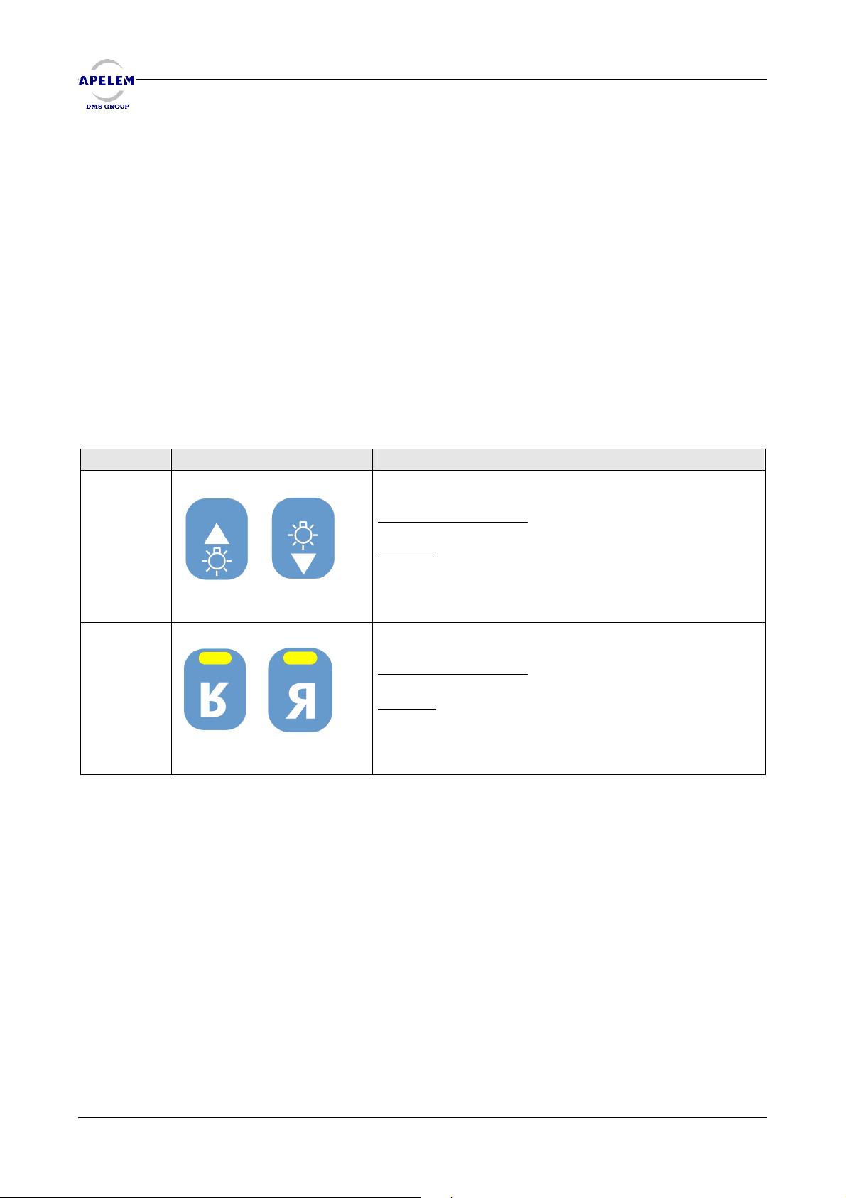
KEY DESCRIPTION FUNCTION
39 & 40
These keys control the TV chain monitor brightness.
Operating conditions
Remark
: None.
: None.
35 & 36
39 40
35 36
These keys control the camera scan reverses.
Operating conditions
Remark
10 ( see parameters configuration).
: Keys may reverse the controls of the joystick
: None
44/54 [Doc: 80-40-002. Rev.L] User’s Manual
Page 45
REMOTE CONTROLLED TABLES BACCARA 90/20 & 90/25 HV
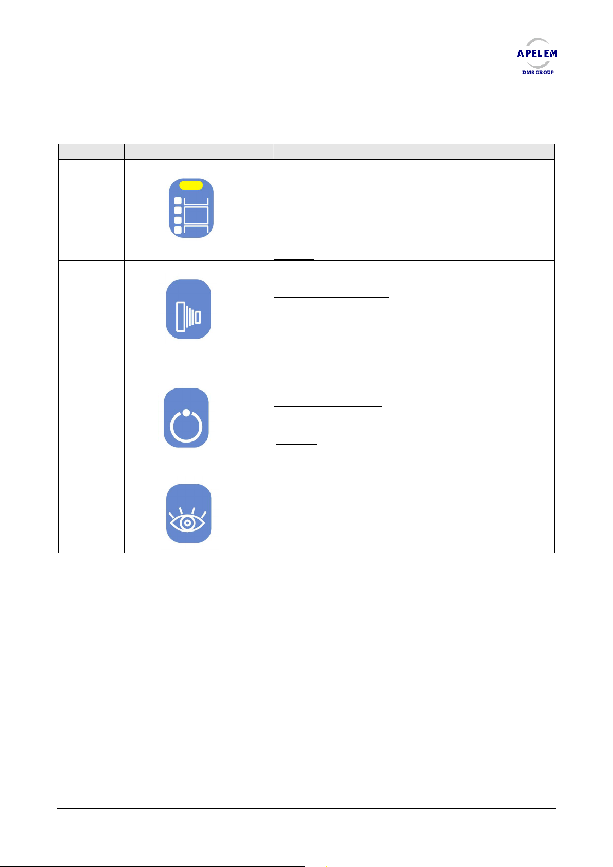
4.2.5. GENERATOR CONTROLS
KEY DESCRIPTION FUNCTION
20
25
26
27
Allows to select the digit mode (led switched on =
mode digit activated)
Operating conditions
holder stays in the parking position and the exposure is
performed on the image intensifier.
Remark
Performs the exposure.
Operating conditions
pushed in with a cassette inside, the first time activated
(preparation) and the ready signal present from the
generator.
Remark
Prepares the graphy.
Operating conditions
cassette.
Remark
Performs the fluoroscopy and may also push in the
cassette holder.
Operating conditions
Remark
pedal.
: External order possibility for the generator.
: The tube must be centered.
: The tube must be centered.
: Operates at the same time as the fluoroscopy
: In preparation the cassette
: The cassette holder must be
: Cassette holder pushed in with
: The tube must be centered.
User’s Manual [Doc: 80-40-002. Rev. L] 45/54
Page 46
REMOTE CONTROLLED TABLES BACCARA 90/20 & 90/25 HV
BACCARA 90/20 & 90/25 HV
BACCARA 90/20 & 90/25 HVBACCARA 90/20 & 90/25 HV
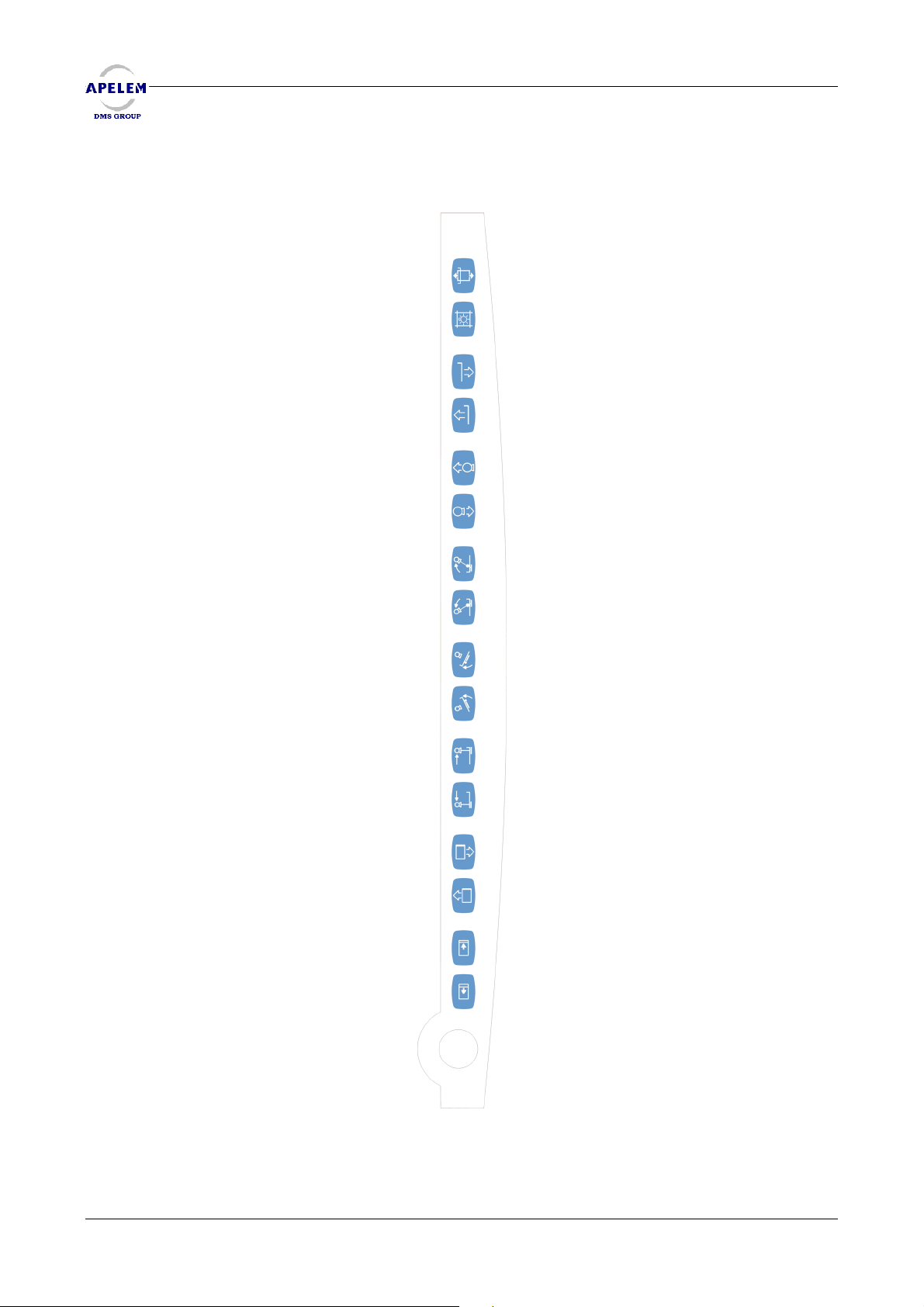
4.3. TABLE CONTROL PANEL
46 47 48 49 50 51 52 53 54 55 56 57 58 59 60 61
46/54 [Doc: 80-40-002. Rev.L] User’s Manual
Page 47
REMOTE CONTROLLED TABLES BACCARA 90/20 & 90/25 HV
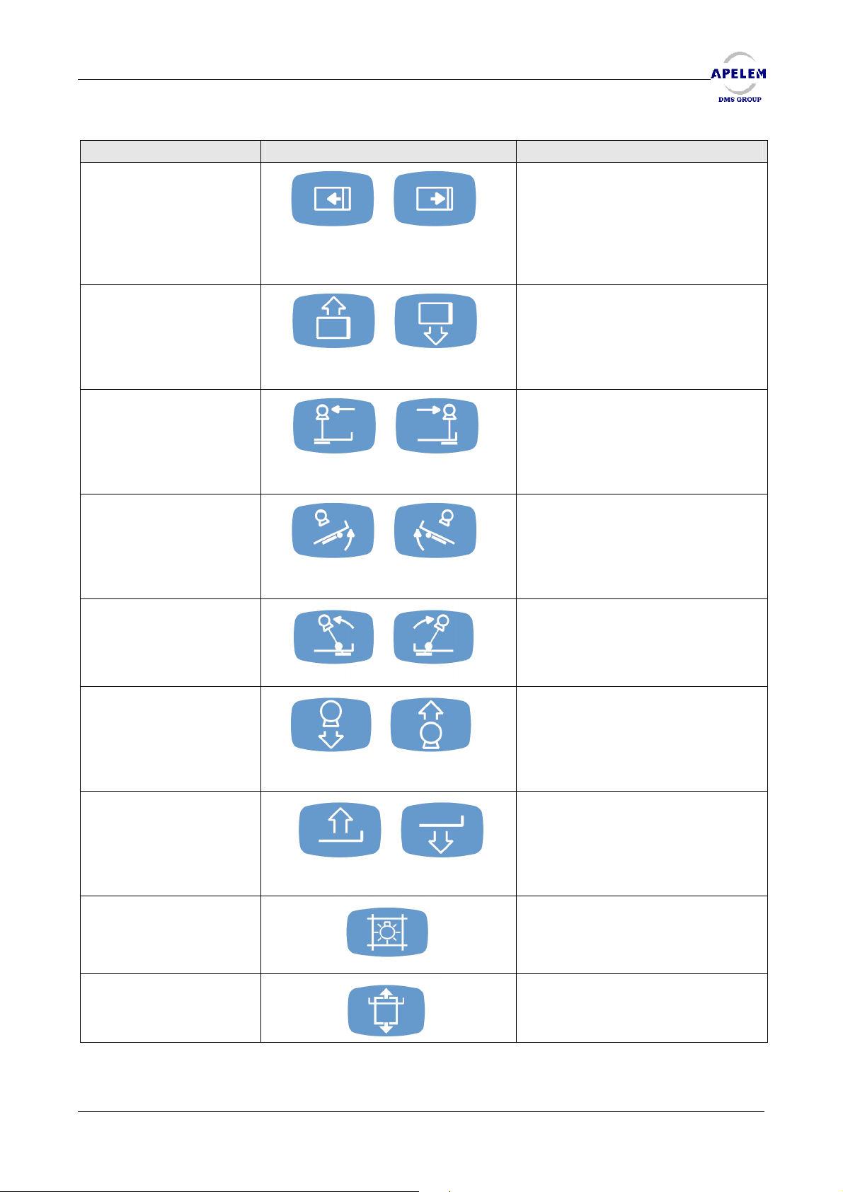
KEY DESCRIPTION FUNCTION
Move the optional longitudinal
panel option.
46 & 47
48 & 49
50 & 51
Pressing simultaneously on both
Keys will re centre automatically
the longitudinal panel.
Move the lateral panel.
Move the carriage .
52 & 53
54 & 55
56 & 57
58 & 59
60
Allow to tilt the table.
Pressing simultaneously on both
Keys put the table in horizontal
position.
Allow to tilt the tube.
Pressing simultaneously on both
Keys will recentre automatically
the column.
Allow to move up and down the
tube (focal).
Allow the ascent or the descent of
the BACCARA table version 90/25
HV.
Switch on the light centering
device.
Allows the cassette input/output.
61
User’s Manual [Doc: 80-40-002. Rev. L] 47/54
Page 48
REMOTE CONTROLLED TABLES BACCARA 90/20 & 90/25 HV
BACCARA 90/20 & 90/25 HV
BACCARA 90/20 & 90/25 HVBACCARA 90/20 & 90/25 HV
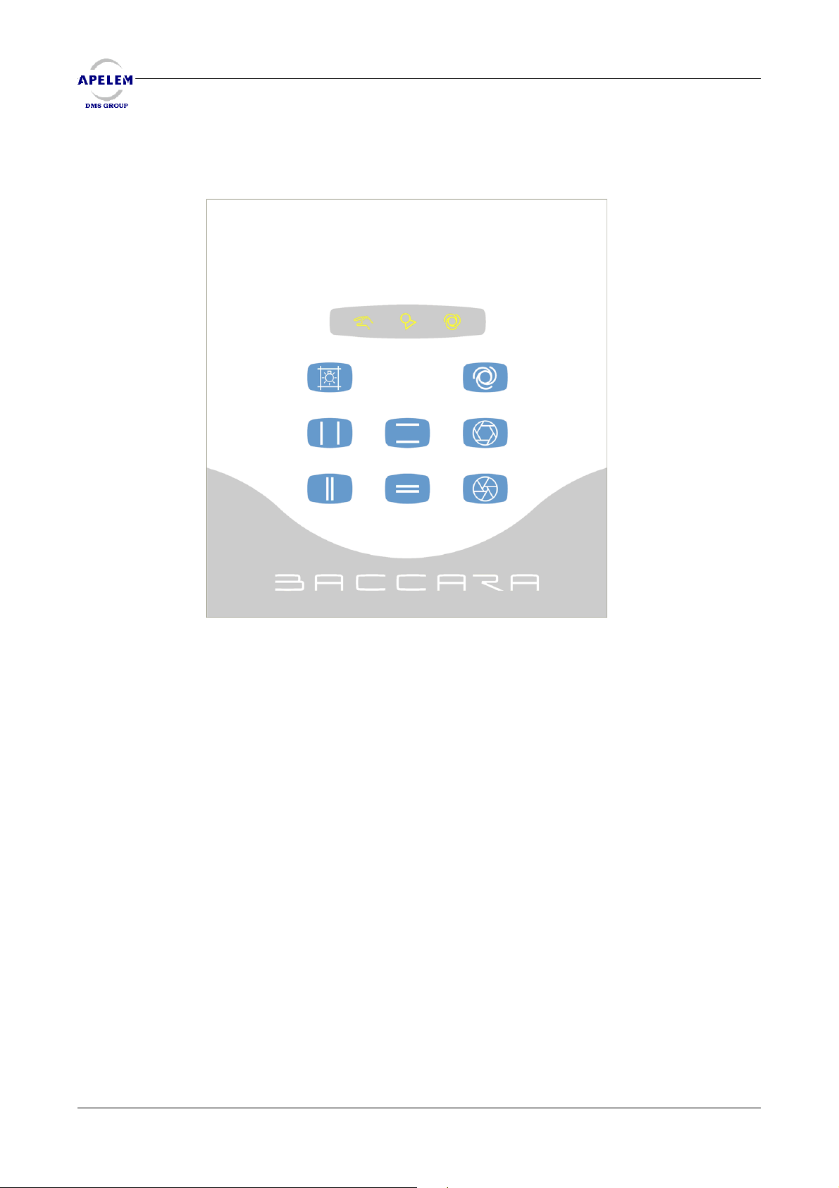
4.4. COLLIMATOR CONTROL PANEL
69 70 68
60 65
63
61 66
64
62 67
48/54 [Doc: 80-40-002. Rev.L] User’s Manual
Page 49
REMOTE CONTROLLED TABLES BACCARA 90/20 & 90/25 HV
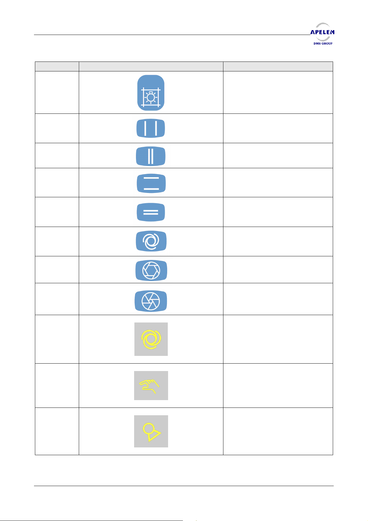
KEY DESCRIPTION FUNCTION
Switches on the light-centering
device.
60
61
62
63
64
65
66
Controls the opening of the
collimator shutters on X axe.
Controls the closing of the
collimator shutters on X axe.
Controls the opening of the
collimator shutters on Y axe.
Controls the closing of the
collimator shutters on Y axe.
Setting of the collimator in
automatic mode.
Controls the iris opening .
Controls the iris closing .
67
68
69
70
User’s Manual [Doc: 80-40-002. Rev. L] 49/54
Selection of automatic mode
Selection of manual mode
Indicator light 70 switched on =
tube off-centre.
Page 50

REMOTE CONTROLLED TABLES BACCARA 90/20 & 90/25 HV
Page intentionally left blank
BACCARA 90/20 & 90/25 HV
BACCARA 90/20 & 90/25 HVBACCARA 90/20 & 90/25 HV
50/54 [Doc: 80-40-002. Rev.L] User’s Manual
Page 51
REMOTE CONTROLLED TABLES BACCARA 90/20 & 90/25 HV
5. ERROR CODE S
ERROR TITLE EXPLANATION
1 « Move up the compressor » This warning message is displayed on the LCD of
the console when the operator asks for a
mechanical movement and when the
compressor is not in its highest position, i.e at rest.
Some mechanical movements may be
dangerous when the compressor is used and
when a patient is immobilized beneath it. This is
why some movements are prohibited as long as
the compressor is not positioned in its highest
position. The highest position is reached when the
indicator light located above the compressor is
turned on.
The movements that can cause this error type are:
· The carriage of the column –cassette
holder unit.
· A variation of the incidence
· A movement of the lateral panel.
2 « Move down the focal »
3 « Move down the carriage »
4 « Tilt the column »
5 « Tube in ceiling safety »
6 « Image intensifier in ground safety »
7 « Park the ceiling suspension » The ceiling suspension is not on its parking switch.
8 « Arming not performed »
9 « Move up the compressor »
10 « Push in the patient panel »
11 « Ceiling interdictions »
12 « Move down the table »
13 « Trolley out of position »
14 « Centre the column »
15 « Collimator in automatic »
16 « Compressor engaged »
17 « Move up the table. »
18 « Table in over run. » This message displays when a problem has
caused a mechanical part movement out of its
normal operating area. It this problem was
caused by a wrong movement during the
calibration phase, please refer to the chapter
« how to restart the remote controlled table after
a disruption caused by a movement which has
activated an over travel contact? »
If this problem has occurred in the normal
operating mode, you must immediately call the
technical department, which will proceed to an
analysis of the breakdown.
19 « Leave the digital technique »
If the BACCARA table is equipped with a manual
spot film device, you must leave the digital
technique of the generator when you insert a
cassette in the holder.
User’s Manual [Doc: 80-40-002. Rev. L] 51/54
Page 52
REMOTE CONTROLLED TABLES BACCARA 90/20 & 90/25 HV
BACCARA 90/20 & 90/25 HV
BACCARA 90/20 & 90/25 HVBACCARA 90/20 & 90/25 HV
20 « Move out the lateral bed patient» If the BACCARA table is equipped with an HV
elevator, when you want to tilt the table in vertical
position, it is necessary to move out the lateral
bed patient in order to avoid a internal collision
between the elevator guide rail and the right arm
of the support panel.
NB: It is possible to set the parameter 726 before
90° in order to avoid that the table reach this
position.
21 « Structure elevation elevating
90/25HV table »
22 «Failure potentiometer P1 bed
patient»
23 «Failure potentiometer P2 tilting» Identical to error 22.
24 «Failure potentiometer P3 spot film
device»
25 «Failure potentiometer P4
column»
26 «Failure potentiometer P7 focal» Identical to error 22.
27 «Failure potentiometer P9
elevator»
In the case of a BACCARA table equipped with a
HV elevator, this message indicates that there is a
risk of internal collision between the elevator arm
lever and the structure of the panel support
patient.
This message has three normal cases of display:
- Table tilted in vertical position: if you move
up the elevator or if you tilt towards the vertical
limit => gently lower the elevator or gently tilt the
table towards the horizontal position in order to
erase this message.
- Table tilted in Trendelenbourg : If you lower
the elevator, or if you tilt towards the
trendelenbourg limit => gently raise the elevator
or gently tilt towards the horizontal position in
order to erase this message.
- Table in horizontal position: If you lower the
elevator at the minimum => gently raise the
elevator in order to erase this message.
If the system detects an exceeding of the inferior
and superior terminals of the potentiometer, all
table movements watched by potentiometers will
be prohibited.
Check the potentiometer: state, fixing, wiring,
calibration (configuration mode).
Identical to error 22.
Identical to error 22.
Identical to error 22.
52/54 [Doc: 80-40-002. Rev.L] User’s Manual
Page 53
REMOTE CONTROLLED TABLES BACCARA 90/20 & 90/25 HV
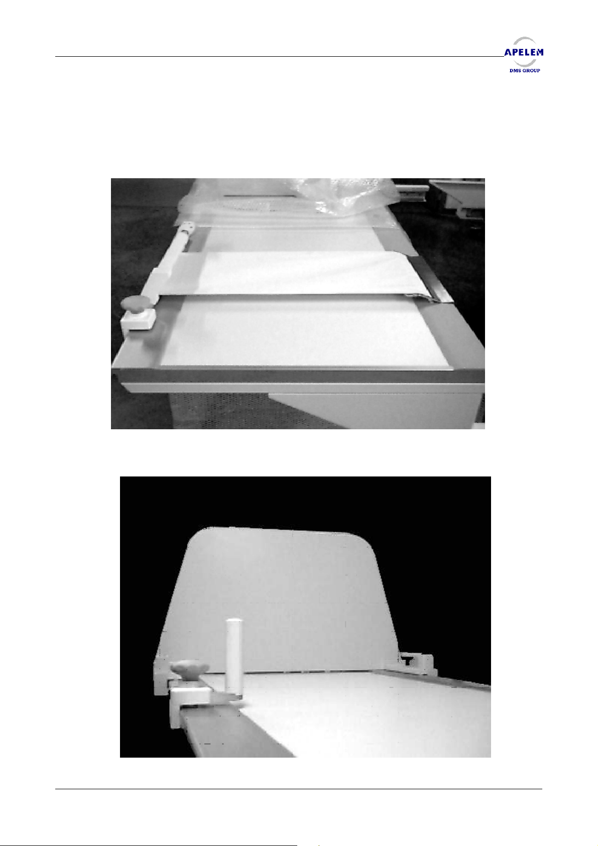
6. POSITIONING AND REMOVING OF ACCESSORIES
Accessories such as handles, footrest, and compression winch are designed to slide on the
rails of the panel.
User’s Manual [Doc: 80-40-002. Rev. L] 53/54
Page 54
REMOTE CONTROLLED TABLES BACCARA 90/20 & 90/25 HV
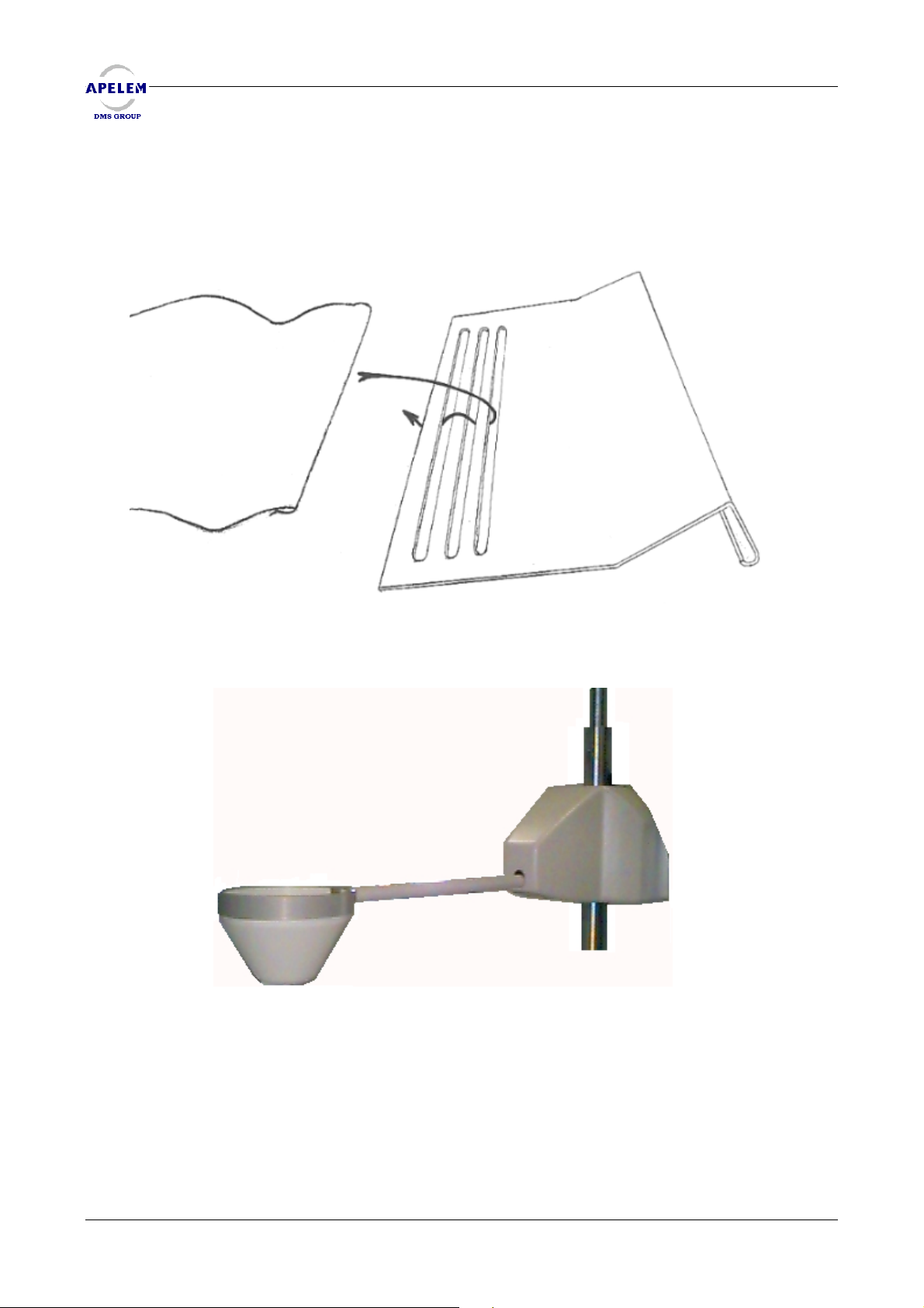
The compression band is held on the winch by a hook for that purpose ; on the other side the
compression is held on the fixing plate as indicated below.
BACCARA 90/20 & 90/25 HV
BACCARA 90/20 & 90/25 HVBACCARA 90/20 & 90/25 HV
Press and turn ¼ around (toward left or right) by pressing to put or to remove the
compression device.
54/54 [Doc: 80-40-002. Rev.L] User’s Manual
 Loading...