


Distributed by
Any reference to Raytheon or RTN in this manual should be interpreted as Raymarine. The names Raytheon and RTN are owned by the
Raytheon Company.


Apelco GPS11 Installation and Operation Handbook
The technical and graphical information contained in this handbook, to the best of our knowledge, was correct as it went to press. However, the Raytheon policy of continuous improvement and updating may change product specifications without prior notice. Therefore, unavoidable differences between the product and handbook may occur from time to time, for which liability
cannot be accepted by Raytheon.
Copyright Raytheon Marine Europe 1998

Apelco GPS11 Installation and Operation Handbook
Package Contents
Checking your GPS11 Package
The GPS11 package contains the following standard items:
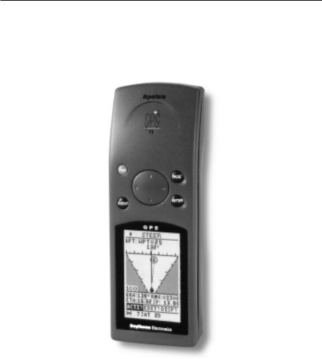
1.Display unit with an internal antenna
2.Lanyard
3.Velcro fixing
4. |
Mounting bracket |
(GPS11 plus only) |
5. |
Power and Data connector |
(GPS11 plus only) |
6.Installation & Operation Guide
7.Warranty document
Items Missing?
If any of the above items are missing or damaged, please contact your Apelco dealer or our Product Support Department to obtain replacement parts. Please note that missing or damaged items cannot be replaced without proof of purchase.
Registering this Product
Once you have checked that you have all of the listed components, please take the time to complete the warranty document and return it to your national distributor.
By returning this document you will receive prompt and expert attention should you ever experience any difficulties with this product. Also, your details are added to our customer database so that you automatically receive new product brochures as and when they are released.

Apelco GPS11 Installation and Operation Handbook
Package Contents
PWR
PAGE
ENTER
MARK
D4127-1
Standard GPS11 package
D4128-1 |
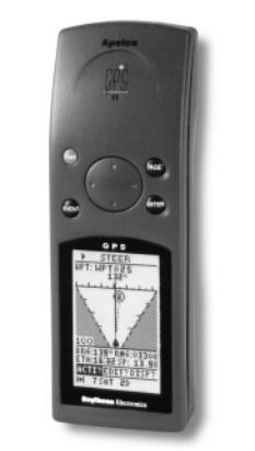
GPS plus package (see page 12 for accessory pat numbers)

Apelco GPS11 Installation and Operation Handbook

Contents
Contents
Checking your GPS11 Package |
2 |
Chapter 1: Introduction |
7 |
Chapter 2: Installation |
9 |
2.1“Velcro” Strap mounting |
9 |
2.2 Bracket Mounting ( GPS11 plus only) |
9 |
2.3 Accessories |
12 |
2.4 External Power connection |
14 |
2.5 External Data Connection |
14 |
Chapter 3: Getting Started |
15 |
3.1 Inserting the batteries |
15 |
3.2 Switching the unit ON and OFF |
16 |
3.3 Light and Contrast |
17 |
3.4 Selecting different pages |
18 |
3.5 Status indicator |
18 |
3.6 Setup |
19 |
3.7 Marking Events |
25 |
3.8 Man Over Board (MOB) |
26 |
Chapter 4: Operation |
27 |
4.1 Satellites Page |
27 |
4.2 Position Page |
29 |
4.3 Waypoint Data Page |
29 |
4.4 Route Data Page |
38 |
4.5 Plotter Page |
48 |

Apelco GPS11 Installation and Operation Handbook
Chapter 5: Fault Finding & Maintenance |
49 |
5.1 Fault Finding |
49 |
5.2 How to Contact Apelco |
49 |
5.3 Maintenance |
52 |
Chapter 6: Specification |
53 |
Appendix A : Chart Datums |
57 |
Appendix B : NMEA Output Specifications |
67 |
Chapter 1: Introduction |
7 |
|
|
Chapter 1: Introduction
Congratulations on the purchase of your Apelco GPS11.
This unit is a navigational system consisting of a radio-positioning receiver making use of signals from the NAVSTAR GPS (Global Positioning System). The system offers simultaneously, high accuracy, continuous cover and worldwide availability.
This unit may be operated as a purely standalone system supplied by its own internal batteries or may be connected to an external 12v supply and integrated with further instumentation via a NMEA data link.
For fixed installation a bracket is provided to allow secure fixing in a wide variaty of positions.
8 |
Apelco GPS11 Installation and Operation Handbook |
|
|
Important Information
All Raytheon equipment and accessories are designed to the highest standard for use in the leisure marine environment.
Their design and manufacture conforms to the latest Electromagnetic Compatibility (EMC) standards, but good installation is required to ensure that performance is not compromised. Although every effort has been taken to ensure that they will perform under all conditions, it is important to understand what factors could affect the operation of the product. To avoid the risk of EMC problems, all Raytheon equipment and cables connected to it should be;
At least 1m (3 feet) from any equipment transmitting or cables carrying radio signals e.g. VHF radios, cables and antennas. In the case of SSB radios, the distance should be increased to 2m (7ft).
At least 20m (66 feet) from large vessels equipped with radar.
More than 2m (7 feet) from the direct path of a radar beam.
The following points should also be noted;
Genuine Raytheon cables should be used at all times. Cutting and rejoining these cables can compromise EMC performance and so should be avoided unless doing so is detailed in the installation manual.
Raytheon equipment should be serviced only by authorised Raytheon service engineers. They will ensure that service procedures and replacement parts used will not affect EMC performance. There are no user serviceable parts in any Raytheon product.
Voltage drops below 10v in the power supply to our products can cause the equipment to reset. This will not damage the equipment but will cause the loss of some information and can change the operating mode. This most frequently happens during engine starting, and so to reduce the risk of this occurring, it is recommended that the equipment is supplied from a different battery than the one used for engine start.
Some products generate high voltages, and so never handle the cables/ connectors when power is being supplied to the equipment.
Always check the installation before going to sea to make sure that it is not affected by radio transmissions, engine starting etc.
In some installations, it may not be possible to prevent the equipment from being affected by external influences. In general this will not damage the equipment but can lead to it resetting, or momentarily result in faulty operation.
Please keep these notes for future reference.
Chapter 2: Installation |
9 |
|
|
Chapter 2: Installation
This chapter covers installation of the support bracket and external cable of the GPS11. If the unit is to be used purely as a standalone handheld GPS then this chapter may be ignored.
2.1 “Velcro” Strap mounting
The unit is supplied with a “Velcro” strip which may be attached to the rear case using the lanyard slots. Ensure that the strap is pulled tight and the end tabs turned back and secured to the main strap.
Attach the fixing strip to the desired surface using glue or double sided tape or sew the strip onto clothing.
2.2 Bracket Mounting ( GPS11 plus only)
The unit is supplied with a universal mounting bracket (selected models only) which will allow your GPS to be slotted into a permanent storage/operating position.
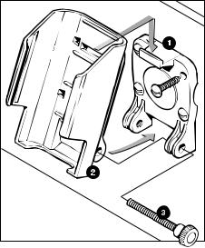
2.2.1 Fixed to a vertical bulkhead
Select your desired position and screw the backplate (1) to the vertical bulkhead. Slot the main bracket (2) onto the top tab of the backplate and then push the bottom of the main bracket back, to allow the supplied finger bolt (3) to secure the base of the bracket.
D4117-1 |
10 |
Apelco GPS11 Installation and Operation Handbook |
|
|
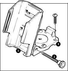
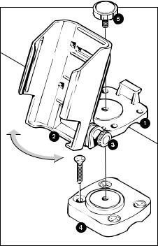
2.2.2 Fixed to a horizontal surface
The bracket may be fixed such that it may be adjusted vertically only or such that it may be rotated and adjusted vertically.
For vertical adjustment only screw the backplate (1) to the desired horizontal surface and then secure the main bracket (2) at the desired angle using the finger bolt (3).
D4116-1 |
Chapter 2: Installation |
11 |
|
|
To allow the bracket to be rotated assemble the backplate (1) to the main bracket (2) using the finger bolt (3). The angle may be adjusted later if required. Select your desired position and screw the base plate (4) to the horizontal surface, then attach the backplate to the baseplate using the finger bolt (5).
D4118-1 |
12 |
Apelco GPS11 Installation and Operation Handbook |
|
|
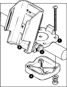
2.2.3 Fixed to a rail
The bracket may be mounted to a rail using the same method as for mounting to a horizontal surface but by reversing the base plate and using stainless steel nuts and bolts (not supplied) to clamp the base plate to the back plate around the rail.
D4119-1 |
2.3 Accessories
Carry Case
Part No. P36003
A soft carry case is available to protect your GPS11 unit.
Bracket Assembly
Part No. P36004 (included in GPS11 plus)
To allow the standard GPS11 unit to be bracket mounted the bracket assembly that is included in the GPS11 plus kit is available separately.
Chapter 2: Installation |
13 |
|
|
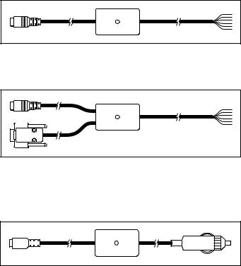
External Connection
There are three external cable accessories available which may be used to connect your GPS11 to external power and data sources.
Part No. P36001 Power and Data Cable (included in GPS11 plus)
D4124-1
Part No. P36005 Power and Data Cable + PC Connector
D4126-1
Note: |
Ensure that any unused cores are isolated to prevent data loss |
|||||||||
|
Part No. P36002 Power Cable with Cigar Lighter Adapter |
|||||||||
|
|
|
|
|
|
|
|
|
|
|
|
|
|
|
|
|
|
|
|
|
|
|
|
|
|
|
|
|
|
|
|
|
D4125-1
14 |
Apelco GPS11 Installation and Operation Handbook |
|
|
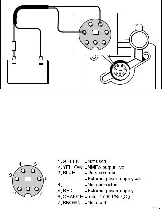
2.4 External Power connection
The GPS11 may be connected to an external power supply between 10V and 24V d.c..
Connection is made via any of the Power/Data cables shown on page 13 and should be protected by a 5 Amp fuse or circuit breaker.
|
|
|
Red |
|
Blue |
4 |
5 |
|
|
|
|
|
|
3 |
6 |
Red |
|
|
|
|
|
|
|
5 Amp |
Blue |
2 |
7 |
|
|||
|
|
|
1 |
10V - 32V d.c. |
|
|
|
|
|
|
D4121-1 |
2.5 External Data Connection
The GPS11 is capable of outputing data to other navigational instrumentation or accepting waypoint information from an external source (P.C.).
Connection is made via the supplied Power/Data cable.
|
|
|
|
|
|
|
|
|
|
|
|
|
|
|
|
|
|
|
|
|
|
|
|
|
|
|
|
|
|
|
|
|
|
|
|
|
|
|
|
|
|
|
|
|
|
|
|
|
|
|
|
|
|
|
|
|
|
|
|
|
|
|
Note: |
Data communications protocols must be set up correctly in the |
|||||||
|
“SET-UP PORT” section, see page xx. |
|||||||
Chapter 3: Getting Started |
15 |
|
|
Chapter 3: Getting Started
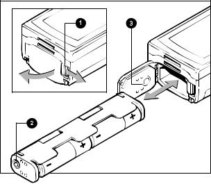
3.1 Inserting the batteries
Open the battery cover on the base of the unit by pulling the compartment latch (1) towards the side of the unit. The battery cover will spring open revealing the black battery carrier within.
Remove the carrier and insert the four AA size batteries following the + and - marks.
Insert the loaded carrier back into the unit taking care to line up the stud (2) on the carrier with the mark on the cover seal (3).
Close the battery cover and pull the latch toward the side of the unit.
The cover will click into position sealing the battery compartment.
Note: |
The cover will not close if the battery carrier has been inserted |
|
incorrectly. |
D4120-1 |

16 |
Apelco GPS 11 Installation and Operation Handbook |
|
|
3.2 Switching the unit ON and OFF
Press the PWR button to switch on your GPS11. The Startup screen will be displayed for 5 seconds.
startup
After 5 seconds the GPS satellite information page will be displayed showing the number and identification of the satellites being received.
satstat
To switch off your GPS11 press and hold down the PWR button. After a one second delay a countdown display will appear. Keep the PWR button held down for a further three seconds until the display switches off.

Chapter 3: Getting Started |
17 |
|
|
3.3 Light and Contrast
After startup the illumination and contrast may be adjusted by pressing the PWR button momentarily.
|
lgtcon |
|
|
Use the trackpad up/down arrows to highlight “BACKLIGHT”, |
|
|
“CONTRAST” or “BACKLIGHT TIME” and press ENTER to |
|
|
select. |
|
|
BACKLIGHT: |
Use the up/down arrows to select ON or OFF |
|
|
then ENTER to store. |
|
CONTRAST: |
Use the left/right arrows to increase or |
|
|
decrease the contrast to the desired level then |
|
|
ENTER to store. |
|
BACKLIGHT TIME: Use the up/down arrows to select the option |
|
|
|
required then ENTER to store. |
|
|
Options are: |
|
|
15 or 30 seconds |
|
|
1, 2 or 4 minutes |
|
|
Continuous |
|
Press PAGE to return to the last screen. |
|
Note: |
The backlight will reduce the battery life. The continuous setting is |
|
|
not recommended unless the unit is connected to an external power |
|
|
supply. |
|
18 |
Apelco GPS 11 Installation and Operation Handbook |
|
|
3.4 Selecting different pages
Use of the PAGE button allows the unit to move through the sequence of main operating pages:
>SATELLITES <
>POSITION <
>WAYPOINT DATA <
>ROUTE DATA <
>PLOTTER <
Each page has a menu bar near the bottom of the display. To access a menu use the left/right arrows on the trackpad to highlight the appropriate title and then press ENTER to activate the menu.
3.5 Status indicator
The bottom line of the screen shows the units current status and cycles though three sets of information:
Battery Status:
Full
Half
Low
Number of Satellites being tracked:
Chart Datum selected:
Position Fix:
Illumination:
Operating Mode:
Differential Fix:
Chapter 3: Getting Started |
19 |
|
|
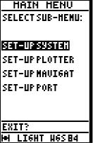
3.6 Setup
Basic Setup of the GPS11 unit is accessed by highlighting SETUP? on the menu bar on the SATELLITES page.
The Setup section is then divided into four sub-menus:
SET-UP SYSTEM
SET-UP PLOTTER
SET-UP NAVIGAT
SET-UP PORT
Sub menus are accessed by highlighting the appropriate line and pressing ENTER.
After switching on select “SETUP?” on the menu bar using the trackpad. Press ENTER to display the main menu.
Mainmen1
20 |
Apelco GPS 11 Installation and Operation Handbook |
|
|
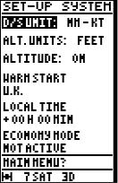
Set-up System
Use the trackpad to select “SET-UP SYSTEM” and press ENTER.
Setsys
Use the trackpad to highlight the desired option:
D/S UNIT:
Press ENTER to select the desired units for Speed and Distance.
Highlight the desired option and press ENTER to select.
Options are: KM - KPH, NM - KT, MI - MPH.
ALT. UNITS:
Press ENTER to select the desired units for altitude.
Highlight the desired option and press ENTER to select.
Options are: METRE, FEET,
ALTITUDE:
Press ENTER to select whether to display or not the altitude information on the Position page..
Options are: ON -display altitude / OFF - not display altitude
Chapter 3: Getting Started |
21 |
|
|
WARM START
|
Press ENTER to select a start area: |
|
AUTO - The unit will search for all satellites and will initiate a |
|
cold start if the unit has moved location while switched off. |
|
“Selection” - A local area may be selected instructing the unit to |
|
search for selected satellites first. |
Note: |
When the unit is first switched on the setting of the correct Warm |
|
Start region will greatly reduce the time to first fix. The auto setting |
|
could result in a time to first fix in excess of 30 minutes. |
LOCAL TIME
Press ENTER to select a time offset from UTC.
Use the trackpad to input the correct local time difference for the area you are in and press ENTER to select.
|
ECONOMY MODE |
|
Stops GPS reception to increase the battery life of the unit. Use this |
|
setting for entering waypoint and route information whilst the unit is |
|
not being used for navigation. |
|
Options are: ACTIVE - reception disabled |
|
NOT ACTIVE - reception enabled |
Note: |
Setting is returned to NOT ACTIVE on power up. |
MAIN MENU?
Highlight this option and press ENTER to return to the main menu.
 Loading...