

Page 1

English User's Manual
Page 2

Main Tech Support:
Phone ......................... +353 91 702020
Fax .............................. +353 91 755275
E-Mail......................... apceurtech@apcc.com
Toll-Free Numbers:
Ireland ........................ 1-800-702000 x2045
Austria ........................ 0660 6480
Belgium ...................... 0800 15063
Czech Republic .......... 0800 102063
Denmark .................... 800 18 153
France ......................... 0800 906 483
Finland ....................... 9800 13 374
Germany .................... 0130 818907
Holland ...................... 0800 0224655
Hungary ..................... 00800 12221
Israel ........................... 177 353 2206
Italy............................. 1678 74731
Luxembourg............... 0800 2091
Norway ....................... 800 11 632
Poland ........................ 00800 353 1202
Portugal ...................... 050 553182
South Africa ............... 0800 994206
Spain........................... 900 95 35 33
Sweden ....................... 020 795 419
Switzerland................. 0800 556177
Turkey ........................ 0800 353 90275
United Kingdom ........ 0800 132990
Not Toll-Free Numbers:
Russia ......................... +7 095 916 7166
Page 3

Important Safety Instructions!Important Safety Instructions!
Important Safety Instructions!
Important Safety Instructions!Important Safety Instructions!
Please read this manual!
Veuillez lire ce manuel!
Bitte lesen Sie dieses Anleitungshandbuch!
¡Se ruega leer este manual de instrucciones!
This User's Manual provides safety, installation and operating instructions that will help you derive the fullest performance and
service life that the SymmetraTM Power Array has to offer.
PLEASE SAVE THIS USER'S MANUAL! It includes important instructions for the safe use of the SymmetraTM Power Array, and
for obtaining factory service should the proper operation of the system or the components come into question. Service or storage
issues may arise at a later date, and may require reference to this User's Manual, or to the technical support information that is
included in it.
CONSERVER CES INSTRUCTIONS! Cette notice contient des instructions importantes concernant la sécurité.
Radio Frequency Interference
NOTE: This equipment has been tested and found to comply with the limits for a Class A digital device, pursuant to Part 15 of the
FCC Rules and the Class A limits for radio noise emissions from digital apparatus set out in the Radio Interference Regulations of
the Canadian Department of Communications. These limits are designed to provide reasonable protection against harmful interference when the equipment is operated in a commercial environment. This equipment generates, uses and can radiate radio
frequency energy and, if not installed and used in accordance with the instruction manual, may cause harmful interference to
radio communications. Operation of this equipment in a residential area is likely to cause harmful interference in which case the
user will be required to correct the interference at his own expense.
Shielded cables must be used with this unit to ensure compliance with the Class A FCC limits.
WARNING: Changes or modifications to this unit not expressly approved by the party responsible for compliance could void the
users authority to operate the equipment.
Part #: 990-7779 Rev. 1
Revised 3/98
Page 4

Limited Warranty
American Power Conversion (APC) warrants its products to be free from defects in materials and workmanship for a period of one
year from the date of purchase. Its obligation under this warranty is limited to repairing or replacing, at its own sole option, any
such defective products. To obtain service under warranty you must obtain a Returned Material Authorization (RMA) number
from APC or an APC service center. Products must be returned to APC or an APC service center with transportation charges
prepaid and must be accompanied by a brief description of the problem encountered and proof of date and place of purchase.
This warranty does not apply to equipment which has been damaged by accident, negligence, or mis-application or has been
altered or modified in any way. This warranty applies only to the original purchaser who must have properly registered the
product within 10 days of purchase.
EXCEPT AS PROVIDED HEREIN, AMERICAN POWER CONVERSION MAKES NO WARRANTIES, EXPRESS OR IMPLIED,
INCLUDING WARRANTIES OF MERCHANTABILITY AND FITNESS FOR A PARTICULAR PURPOSE. Some states do not
permit limitation or exclusion of implied warranties; therefore, the aforesaid limitation(s) or exclusion(s) may not apply to the
purchaser.
EXCEPT AS PROVIDED ABOVE, IN NO EVENT WILL APC BE LIABLE FOR DIRECT, INDIRECT, SPECIAL, INCIDENTAL,
OR CONSEQUENTIAL DAMAGES ARISING OUT OF THE USE OF THIS PRODUCT, EVEN IF ADVISED OF THE POSSIBILITY OF SUCH DAMAGE. Specifically, APC is not liable for any costs, such as lost profits or revenue, loss of equipment, loss of use
of equipment, loss of software, loss of data, costs of substitutes, claims by third parties, or otherwise. This warranty gives you
specific legal rights and you may also have other rights which vary from state to state.
Life Support Policy
As a general policy, American Power Conversion (APC) does not recommend the use of any of its products in life support applications where failure or malfunction of the APC product can be reasonably expected to cause failure of the life support device or
to significantly affect its safety or effectiveness. APC does not recommend the use of any of its products in direct patient care. APC
will not knowingly sell its products for use in such applications unless it receives in writing assurances satisfactory to APC that (a)
the risks of injury or damage have been minimized, (b) the customer assumes all such risks, and (c) the liability of American Power
Conversion is adequately protected under the circumstances.
Examples of devices considered to be life support devices are neonatal oxygen analyzers, nerve stimulators (whether used for
anesthesia, pain relief, or other purposes), autotransfusion devices, blood pumps, defibrillators, arrhythmia detectors and alarms,
pacemakers, hemodialysis systems, peritoneal dialysis systems, neonatal ventilator incubators, ventilators for both adults and infants, anesthesia ventilators, infusion pumps, and any other device designated as critical by the U.S.F.D.A.
Hospital grade wiring devices and leakage current may be ordered as options on many APC UPS systems. APC does not claim that
units with this modification are certified or listed as Hospital Grade by APC or any other organization. Therefore these units do
not meet the requirements for use in direct patient care.
Entire contents copyright © 1998 American Power Conversion. All rights reserved; reproduction in whole or in part without
permission is prohibited. Symmetra, Power Array, SmartSlot, SmartCell and SNMP Adapter are trademarks of APC. Power-
Chute and PowerDoctor are registered trademarks of APC. All other trademarks are the property of their respective owners.
Page 5

TT
able of Contentsable of Contents
T
able of Contents
TT
able of Contentsable of Contents
INTRODUCTION
SAFETY INFORMATION
1. PHYSICAL REPRESENTATION
Theory of Operation ................................................................................................................. i
Modes of Operation .................................................................................................................. iii
Symbols Used In This Manual ......................................................................................... safety-1
Important Safety Instructions .......................................................................................... safety-1
The Power Array Frame ............................................................................................................ 1-1
PowerView User Interface ......................................................................................................... 1-2
Grill Covers ................................................................................................................................ 1-2
Power Module............................................................................................................................ 1-2
Battery Module .......................................................................................................................... 1-2
Main Intelligence Module (MIM) ........................................................................................... 1-3
Redundant Intelligence Module (RIM) ................................................................................... 1-3
Input Circuit Breaker ................................................................................................................ 1-3
Maintenance Bypass Switch ..................................................................................................... 1-3
Rear View of Power Array ......................................................................................................... 1-4
System Enable Switch ................................................................................................................ 1-4
Communication Interface Ports .............................................................................................. 1-4
SmartSlotTM Accessory Ports ..................................................................................................... 1-4
REPO/Input/Output Wiring Panels ........................................................................................ 1-4
Convenience Power Panel ......................................................................................................... 1-4
Extended Run Battery Frame Connector ................................................................................ 1-4
2. SITE PREPARATION
Space and Weight Considerations ........................................................................................... 2-1
Transporting Power Array to Installation Site ........................................................................ 2-1
Operating Conditions ............................................................................................................... 2-1
BTU Output ............................................................................................................................... 2-1
3. UNPACKING AND INSTALLING FRAME
Initial Inspection ....................................................................................................................... 3-1
Check For Damage .................................................................................................................... 3-1
Handling Considerations ......................................................................................................... 3-1
Move the Frame ......................................................................................................................... 3-1
Remove Packing Materials........................................................................................................ 3-2
Remove the Frame from the Pallet .......................................................................................... 3-2
Moving Battery & Power Modules .......................................................................................... 3-2
4. WIRING REQUIRMENTS & PROCEDURES
Wiring Overview ....................................................................................................................... 4-1
Input Wiring .............................................................................................................................. 4-2
Output Wiring ........................................................................................................................... 4-4
Remote Emergency Power Off Wiring .................................................................................... 4-5
Electrical Wiring Test/Checklist ............................................................................................... 4-6
Page 6

5. SETTING UP THE POWER ARRAY
Overview of Setup ..................................................................................................................... 5-1
Frame Leveling Procedure ........................................................................................................ 5-1
Installing the Battery Modules ................................................................................................. 5-2
Installing the Power Modules ................................................................................................... 5-3
Installing the Main Intelligence Module (MIM) .................................................................... 5-4
Installing the Redundant Intelligence Module (RIM) ........................................................... 5-4
Installing the PowerView Interface .......................................................................................... 5-5
SmartSlotTM Interface Accessories ............................................................................................. 5-6
Installation Test/Checklist ........................................................................................................ 5-7
6. THE POWERVIEW USER INTERFACE
Overview .................................................................................................................................... 6-1
PowerView Functions ............................................................................................................... 6-1
PowerView LED Indicators ...................................................................................................... 6-2
Navigation Keys ......................................................................................................................... 6-2
Startup Screen ........................................................................................................................... 6-3
Top-Level Menu Screen ............................................................................................................ 6-3
Language Configuration ........................................................................................................... 6-4
7. CONFIGURING & OPERATING THE SYMMETRA
Introduction .............................................................................................................................. 7-1
Step #1: Powering the System ................................................................................................... 7-1
Step #2: Powering the Loads ..................................................................................................... 7-2
Step #3: Review Status Conditions .......................................................................................... 7-2
Step #4: Perform a Self Test ...................................................................................................... 7-4
Step #5: Configure Shutdown Parameters .............................................................................. 7-5
Step #6: Configure Alarms ........................................................................................................ 7-5
Step #7: Review Diagnostics Menu .......................................................................................... 7-6
Step #8: Review Logging Menu ................................................................................................ 7-6
8. MODULE REPLACEMENT
Module Failure Alarm Indicators .......................................................................................... 8-1
Technical Support and Obtaining a Replacement Module ................................................. 8-1
Battery Module Replacement Procedure .............................................................................. 8-2
Power Module Replacement Procedure ................................................................................ 8-3
Main Intelligence Module Replacement Procedure ............................................................. 8-4
Redundant Intelligence Module Replacement Procedure ................................................... 8-4
9. POWERVIEW INTERFACE MESSAGES
Start-Up Messages ................................................................................................................... 9-1
General Status Messages ......................................................................................................... 9-2
Module Failure Messages ........................................................................................................ 9-3
Threshold Alarm Messages ..................................................................................................... 9-3
Bypass Messages ...................................................................................................................... 9-3
General Fault Messages ........................................................................................................... 9-4
INDEX
Page 7

Introduction
The APC SymmetraTM Power Array is a
scalable, redundant power protection sys-
tem for multiple servers and business
critical applications. This is an introduction
to the SymmetraTM Power Array.
MiniFrame
MasterFrame
Page 8
Thank YThank Y
Thank Y
Thank YThank Y
ou!ou!
ou!
ou!ou!
Theory of OperationTheory of Operation
Theory of Operation
Theory of OperationTheory of Operation
Thank you for investing in the SymmetraTM Power Array. Please
read this User's Manual thoroughly before installing the system. It provides important information for using the
SymmetraTM safely and effectively.
TMTM
TM
SymmetraSymmetra
Symmetra
SymmetraSymmetra
The SymmetraTM is a high-performance, uninterruptible
power array system, designed for large-scale loads. It provides conditioned, reliable AC power to load equipment, and
provides protection from power blackouts, brownouts, swells,
sags, surges and interference. The SymmetraTM Power Array
system is comprised of either a MiniFrame, or a MasterFrame,
and a variable set of modules. A MiniFrame system can be
configured to deliver a maximum output of 8kVA, and a
MasterFrame system can deliver a maximum of 16kVA.
TMTM
Overview Overview
Overview
Overview Overview
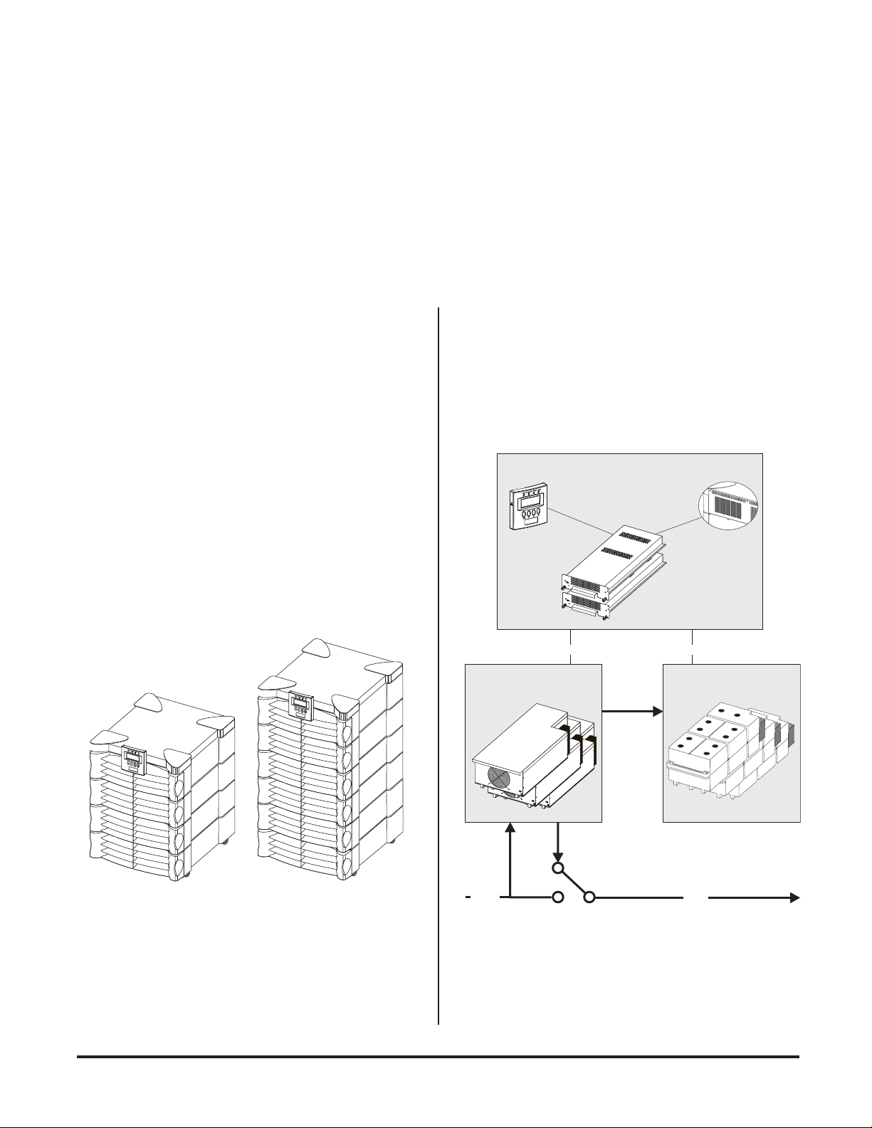
The SymmetraTM Power Array is comprised of three functional components: A power processing system, a battery
source, and a control/user interface system. The relationship
of these functional components is illustrated in figure I-2.
System Control
and Interface
Powerview User
Interface
Communication Communication
Power Processing
Charge
Communication
Card and
SmartSlots
TM
Battery Source
Fig I-1 MiniFrame and MasterFrame
Bypass
Switch
AC
IN
Fig I-2 Functional Diagram of a Symmetra
AC
OUT
TM
i
Page 9

Power PrPower Pr
Power Pr
Power PrPower Pr
ocessing Systemocessing System
ocessing System
ocessing Systemocessing System
ContrContr
Contr
ContrContr
ol/User Interol/User Inter
ol/User Inter
ol/User Interol/User Inter
faceface
face
faceface
The power processing system delivers conditioned AC output
power with a low distortion sinewave. Under normal operating conditions, power is received from the AC mains (utility)
power source, conditioned by the power processing system,
and delivered to the load equipment. In the event of an AC
mains power source failure, the power processing system receives power from the battery source (battery modules), converts it to conditioned AC, and delivers it to the load equipment. When AC mains power is present, the power processing
system also maintains the battery source at full charge.
The power processing system in SymmetraTM is comprised of
one or more power modules. Each power module contains
the electronic components for a complete 4kVA UPS, including
the rectifier, charger and inverter. When two or more power
modules are present, they operate in parallel, sharing the load
equally.
By configuring the system with at least one more power module than is required to power the load (a redundant power
module), SymmetraTM can sustain a power module failure
and still deliver full power to the load equipment. The failed
module is identified by the control/user interface system, an
alarm is initiated to notify the user of the module failure, and
the hot-swappable module can be replaced by the user, without the need to power down the load equipment.
A SymmetraTM MiniFrame provides bays for up to three power
modules, and a MasterFrame provides bays for up to five.
This provides the full system capacity (8kVA and 16kVA respectively), plus one redundant power module.
The control/user interface system coordinates the operation
of the SymmetraTM and reports status conditions via several
user interface options. Functions performed by the control/
user interface component include module coordination and
state control, analysis and reporting of system status, and
reporting of alarm conditions.
Module Coordination & State Control - The Symmetra
incorporates a main intelligence module (MIM) that continuously monitors the system, and delivers data to both the
PowerView user interface, and to the communication ports.
The MIM coordinates the initial power up of the system, transfers it into and out of bypass mode, transfers the power source
between the mains AC power, and the battery source, and
coordinates shutdown operations.
System Status Monitoring - The MIM gathers data about the
system components and delivers it to both the PowerView
interface, and to the computer interface ports. System status
monitoring and reporting data include the current predicted
run time, the status of individual battery and power modules,
the input & output voltage, input & output voltage frequency,
and the size and status of the output load.
Alarm Condition Detection - The control/user interface system monitors the SymmetraTM for alarm conditions. If an
alarm condition is detected, the PowerView user interface initiates an audible and visual alarm. Alarm conditions include
on-battery, low battery, module faults, overloads, loss of redundancy and a variety of other default and user defined events.
All possible alarm messages and the appropriate user responses
are provided in Chapter 9.
TM
BatterBatter
Batter
BatterBatter
The battery source is comprised of parallel, hot-swappable,
120V battery modules. These are housed in the Symmetra
frame, and in an optional XR Extension Battery frame.
A SymmetraTM MiniFrame provides bays for up to two battery modules, and a MasterFrame provides bays for up to
four. Both of these frames can be connected to an XR Extension Battery frame. Additional battery modules increase onbattery run time.
ii
y Soury Sour
y Sour
y Soury Sour
cece
ce
cece
TM
Page 10
Modes of OperationModes of Operation
Modes of Operation
Modes of OperationModes of Operation
The Power Array functions in one of four modes of operation
depending on user commands, the status of the AC mains
(utility) voltage, and the condition of the SymmetraTM itself.
The four modes are Load-Disconnect, On-Line, On-Battery,
and Bypass. The PowerView reports the operating mode.
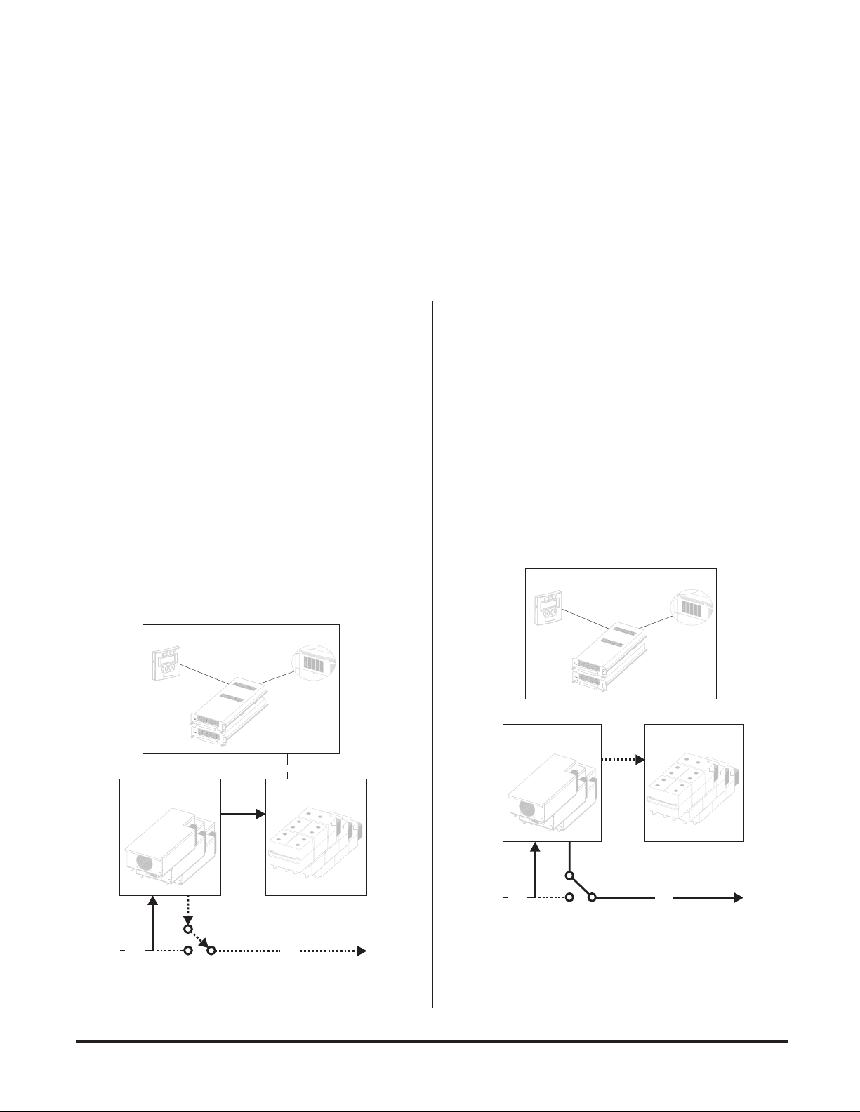
Load-Disconnect Mode
In the load-disconnect mode, incoming mains (utility) power
is present and the system is internally powered, but no output
power is delivered to the load equipment. The Symmetra
enters the load-disconnect mode at the initial power up when
the system enable switch is switched to the on position. When
the system is operating on-line, and the load off command
is entered in the PowerView interface, it returns to the loaddisconnect mode. Figure I-3 illustrates power flow when the
system is operating in the load-disconnect mode.
TM
On-Line Operating Mode
The on-line operating mode is the normal operating mode.
When the system is in the on-line operating mode, the Power
Array receives AC mains (utility) power and delivers conditioned power to the load equipment. The Power Array maintains proper battery charge, regulates the output voltage and
frequency, and protects the load from surges and electrical
noise. SymmetraTM will operate in this mode if it has been
commanded to turn the load on, the incoming utility voltage
is present and functioning properly, and there are no preventing abnormal conditions such as an overload. See figure I-4
for a diagram of the power flow when the system is in the online operating mode.
System Control
and Interface
System Control
and Interface
Powerview User
Interface
Communication Communication
Power Processing Battery Source
Charge
Bypass
AC
IN
Switch
Communication
Card and
SmartSlots
AC
OUT
TM
Fig I-3 Load-Disconnect Operating Mode
Powerview User
Interface
Communication Communication
Power Processing Battery Source
Charge
Bypass
AC
IN
Switch
Communication
Card and
SmartSlots
AC
OUT
TM
Fig I-4 On-Line Operating Mode
iii
Page 11
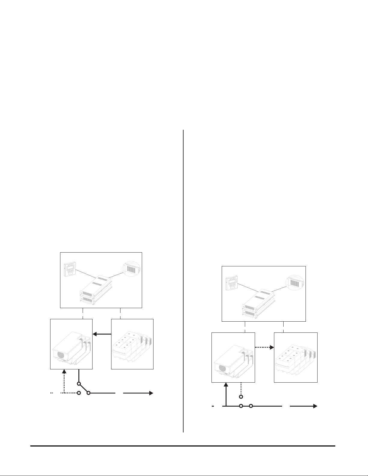
On-Battery Operating Mode
Bypass Operating Mode
When in the on-battery mode, the Power Array draws DC
power from the battery source, converts it to conditioned AC
power and delivers it to the load equipment. Symmetra
TM
typically enters this mode in the event of a mains (utility) power
failure. It will also operate in the on-battery mode during a
user initiated battery self test.
On-battery operation is limited in duration and is dependent
on the number of battery modules, their state of charge, and
the size of the load. SymmetraTM will remain in the on-battery
state until either the incoming utility power is restored or the
batteries are depleted. See figure I-5 for a diagram of power
flow when the system is in the on-battery mode.
System Control
and Interface
Powerview User
Interface
Communication Communication
Power Processing Battery Source
Discharge
Communication
Card and
SmartSlots
TM
When the SymmetraTM is in the bypass operating mode, the
system is bypassed and utility power is delivered directly to the
load. SymmetraTM is equipped with an automatic bypass function to allow the system to automatically go into bypass mode,
and a manual maintenance bypass switch to allow a user to
manually bypass the system. Either can be used to place the
Power Array into bypass operating mode.
The SymmetraTM will automatically transfer to the bypass
operating mode when AC mains power is present, but the
load cannot be powered by the inverter. Events which may
cause this include overloads and failed non-redundant power
modules. The SymmetraTM will automatically return to the
on-line mode when the triggering event clears. Figure I-6 illustrates power flow when the system is in the bypass mode.
System Control
and Interface
Powerview User
Interface
Communication Communication
Power Processing Battery Source
Communication
Card and
SmartSlots
TM
Charge
Bypass
AC
Switch
IN
Fig I-5 On-Battery Operating Mode
AC
OUT
AC
IN
Bypass
Switch
AC
OUT
Fig I-6 Bypass Operating Mode
iv
Page 12

DefinitionsDefinitions
Definitions
DefinitionsDefinitions
Important InformationImportant Information
Important Information
Important InformationImportant Information
The following terms are used in this manual. Review these
definitions for a better understanding of the SymmetraTM:
Redundancy - Indicates the presence of one or more extra
power modules which allow the system to sustain a fault and
still provide protection to the load. To be fully redundant, the
system should be configured with a redundant intelligence
module, and at least one redundant power module.
Note: The number of battery modules determines the length of
the run time. While it is prudent to use the maximum number
of battery modules possible, they are not considered redundant.
N+1 Redundancy - Refers to the level of power module redundancy. N represents the number of power modules required to power the load, and +1, +2, etc. represents the
number of extra power modules that are present.
For example, a 7.3 kVA load requires two power modules for
adequate protection. If the SymmetraTM is configured with
only two modules, it has an N+0, level of redundancy. (No
redundancy). If the system is configured with three power
modules, it has an N+1 redundancy. Depending on the size
of the load, SymmetraTM can be configured with 2, 3 or even 4
extra power modules. Respectively, it would have an N+2,
N+3, or N+4 level of redundancy.
Please read this User's Manual thoroughly before proceeding
with the installation of the SymmetraTM Power Array system.
It provides important information about installing and using
the SymmetraTM safely and effectively. Pay close attention to
text that is accompanied by a danger, or caution symbol. For
technical support, see the inside front cover of this manual.
Capacity - The maximum amount of output power that a
SymmetraTM system can deliver. The capacity is limited by the
lesser of the frame size, or the capacity of the installed power
modules.
For example, a MiniFrame (8kVA) with one power module
installed (4kVA) has a system capacity of 4kVA. A MasterFrame
(16kVA) with five power modules (20kVA) has a system capacity of 16kVA.
Hot-swappable - The modules are hot-swappable means
they can be replaced safely by a user or service provider while
the load is still powered and fully protected.
v
Page 13

vi
Page 14

Safety Information
Important Safety Information
Read this safety information com-
pletely before installing or using the
SymmetraTM Power Array.
MiniFrame
MasterFrame
Page 15

Safety
Symbols Used In This ManualSymbols Used In This Manual
Symbols Used In This Manual
Symbols Used In This ManualSymbols Used In This Manual
The following symbols appear in this User's Manual:
CAUTION/DANGER - Caution indicates risk of
bodily harm. Danger indicates that a risk of electrical shock is present and the associated procedures should be followed carefully.
STAND BY MODE - The system enable switch,
and the input circuit breaker use the stand by
mode. When either of these are switched to stand
by, the Power Array is disconnected from mains
(utility) input voltage. In this mode, the system
appears to be off, although the mains (utility)
power is still connected to the system. For this
reason, the standby mode is unsafe for servicing
the system. Always follow the five step Total Power
Off procedure before servicing the Power Array.
(See procedure at right.)
OFF POSITION - The maintenance bypass
switch is the only switch that can be placed in the
off position. When switched to the off position, the Power Array functions normally, receiving mains (utility) power, and delivering conditioned power to the load equipment.
ON POSITION - All three switches (The system enable switch, the maintenance bypass switch
and the input circuit breaker) can be placed in the
on position. See the description for each of these
switches in Chapter 1.
SAFETY EARTH GROUND - Indicates the primary safety ground.
IMPORIMPOR
IMPOR
IMPORIMPOR
n SAVE THIS USER MANUAL - This manual contains im-
CONSERVER CES INSTRUCTIONS. CETTE NOTICE
CONCERNANT LA SÉCURITÉ.
n Connection to the branch circuit (mains utility power
n Installation of the power and battery modules can be per-
n Operation of the SymmetraTM can be performed by any
n The protective earth conductor for the SymmetraTM car-
n FIVE STEP TOTAL POWER OFF PROCEDURE
TT
ANT SAFETY INSTRUCTIONSANT SAFETY INSTRUCTIONS
T
ANT SAFETY INSTRUCTIONS
TT
ANT SAFETY INSTRUCTIONSANT SAFETY INSTRUCTIONS
portant instructions that should be followed during installation and maintenance of the Power Array, and for
installation or replacement of the battery and power modules.
CONTIENT DES INSTUCTIONS IMPORTANTES
source) must be performed by a licensed electician.
formed by any individual with no previous technical experience.
individual with no previous technical experience.
ries the leakage current from the load devices (computer
equipment). Therefore, the size of the conductor must be
at least as large as the wire required by IEC 950. IEC 950
states the following nominal cross-sectional areas:
- 2.5 mm2 for rated current between 17 & 25 A
- 6 mm2 for rated current between 33 & 40 A
- 10 mm2 for rated current between 41 & 63 A
- 16 mm2 for rated current between 64 & 80 A
To remove all power from the Power Array (Total Power
Off), the following events must occur in the order listed:
1. Set system enable switch to the stand by position.
2. Set input circuit breaker to the stand by position.
3. Remove all battery modules from the Power Array.
4. Disconnect XR external battery cabinet (if present).
5. Disconnect the mains/branch circuit breaker.
Safety-1
Page 16

Safety
n CAUTION: Risk of Electrical Shock and Energy Hazard,
120V, 7.2 Ah battery module. Before replacing battery
modules, remove conductive jewelry such as chains, wrist
watches and rings. High short circuit current through
conductive materials could cause severe burns.
n CAUTION: Do not dispose of batteries or battery mod-
ules in a fire. The batteries may explode.
n CAUTION: Do not open or mutilate battery modules or
batteries. Released electrolyte is harmful to the skin and
eyes. It may be toxic.
n While battery modules are user replaceable, servicing of
the battery modules themselves should be performed or
supervised by personnel knowledgeable of batteries and
the required precautions. Keep unauthorized personnel
away from batteries.
n When replacing or adding battery modules to the Power
Array system, use only the SYBATT SymmetraTM Battery Module. See the APC telephone numbers listed on
the inside cover of this manual for technical support, or
to obtain replacement modules.
Safety-2
Page 17

Chapter One
Physical Representation
This chapter provides an illustrated descrip-
tion of the SymmetraTM Power Array system
and each of the modular components.
Before proceeding, examine the illustration
below. It depicts a MiniFrame (8kVA) and a
MasterFrame (16kVA) Power Array as they
appear during normal operating conditions.
MiniFrame
MasterFrame
Page 18
The Power Array FrameThe Power Array Frame
The Power Array Frame
The Power Array FrameThe Power Array Frame
The SymmetraTM Power Array frame serves as the base for
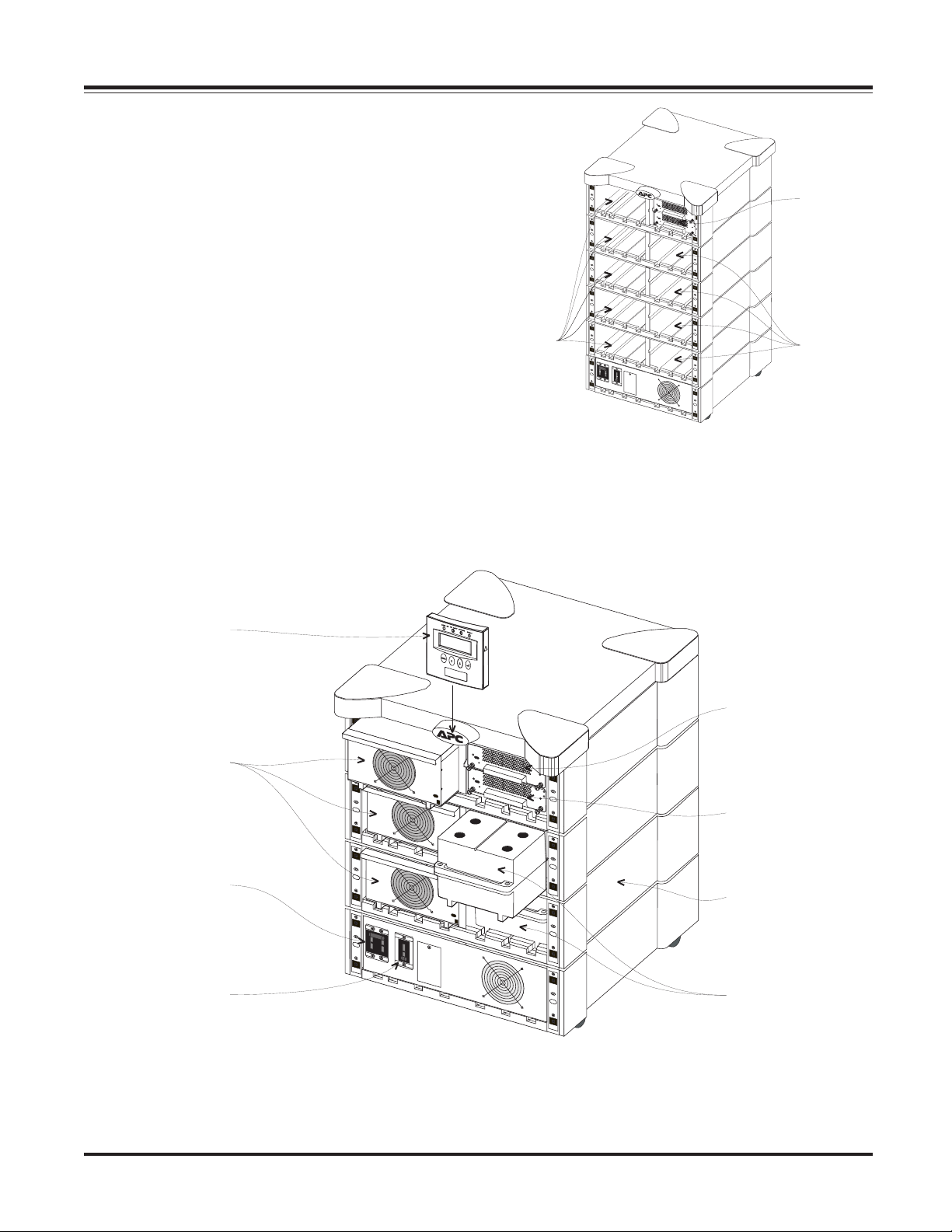
the modular components of the system. The MiniFrame provides bays for three power modules and two battery modules. The MasterFrame provides bays for five power modules and four battery modules. The bay at the top right houses
the main intelligence module (MIM) and redundant intelligence module (RIM).
Wiring input/output access panels and terminal blocks, a system enable switch, an input circuit breaker and a maintenance bypass switch are located near the bottom of the frame.
A MiniFrame with all battery and power module bays loaded
is depicted in figure 1-1. A MasterFrame with factory installed MIM and RIM, and empty power and battery module
bays is depicted in figure 1-2.
Chapter 1 - Physical Representation
Five
Power
Module
Bays
Fig 1-2 An Empty MasterFrame (grill covers removed)
Main
Intelligence
and
Redundant
Intelligence
Modules
Four
Battery
Module
Bays
PowerView
Interface
Power
Modules
Input
Circuit
Breaker
Maintenance
Bypass
Switch
Redundant
Intelligence
Module
Main
Intelligence
Module
MiniFrame
Battery
Modules
Fig 1-1 A Fully Loaded MiniFrame (grill covers removed)
1-1
Page 19
Chapter 1 - Physical Representation
PowerPower
Power
PowerPower
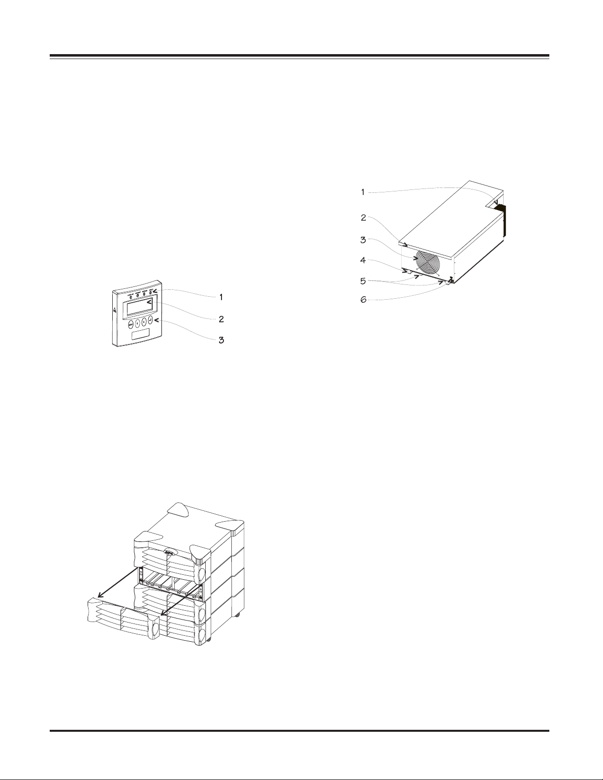
The PowerView incorporates a 4 x 20 alphanumeric LCD
screen with four navigation keys, four LED status indicators,
and an audible alarm. The display communicates with the
Power Array via a short RJ45 connector cable that is hardwired
into the intelligence modules bay. The PowerView can be
mounted on the front of the frame, stand on top of the frame,
or it can be installed at a remote location. A 6.1m (20') RJ45
cable is provided for remote installation.
The alphanumeric LCD screen displays system status, fault
reporting, and module diagnostics information. The navigation keys scroll through an elaborate menu. Chapter 6 provides detailed information about the PowerView.
Alarm thresholds and parameters are set with the PowerView.
In the event of an alarm condition, the PowerView emits both
audible and visual alarm indicators.
view User Interview User Inter
view User Inter
view User Interview User Inter
faceface
face
faceface
Power ModulePower Module
Power Module
Power ModulePower Module
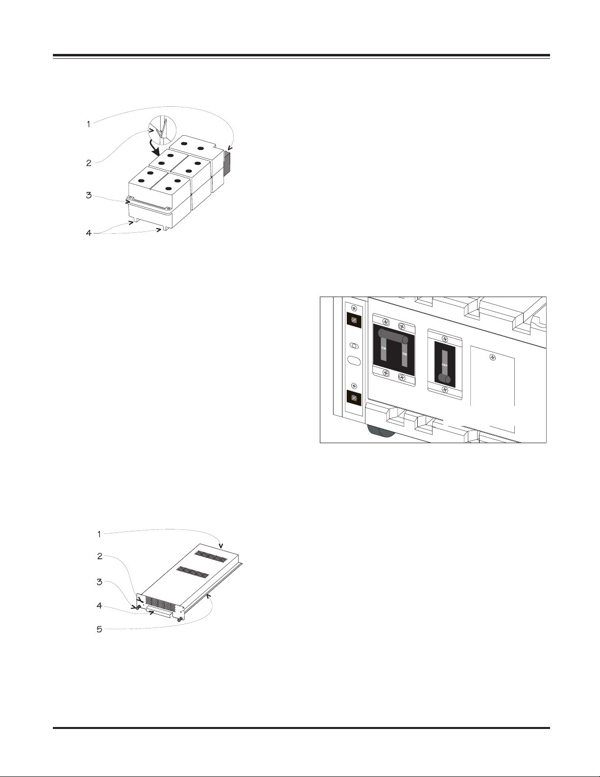
The power module is a self-contained, 4kVA UPS (without
batteries) housed inside a metal enclosure. A blind mating
connector at the rear of the module engages with a connector inside the frame. Power modules are installed in the vertical column of bays at the left of the frame. These bays are
labeled L1, L2, L3, etc.
1-Blind Mating Connector, 2-Positioning Handle,
3-Cooling Fan Grill, 4-Alignment Runners,
5-Seating Tabs, 6-Flip Latch Micro Switch
1-LED Status Indicators, 2-LCD Screen, 3-Navigation Keys
Fig 1-3 PowerView User Interface
Grill CoversGrill Covers
Grill Covers
Grill CoversGrill Covers
Each level of the frame is equipped with a grill cover. These
covers are interchangeable, and snap securely onto the frame.
When removing, temporarily storing, and replacing grill covers, use care to prevent them from being marred or scratched.
Fig 1-5 Power Module
In the event of a power module failure, the PowerView initiates an audible alarm and displays an error message. The
power module is hot-swappable. Instructions for module
replacement are provided in Chapter 8.
BatterBatter
Batter
BatterBatter
The battery module is comprised of a series of ten 12V batteries housed inside a plastic enclosure. A blind mating connector at the rear of the module engages with a connector
inside the frame.
Battery modules are installed in the vertical column of bays
at the right of the frame. These are labeled R2, R3, R4, etc.
(R1 houses the intelligence modules.) The condition and
charge of each battery module is reported on the PowerView.
If a battery module fails, an alarm is initiated. Battery modules are hot-swappable and user replaceable.
y Moduley Module
y Module
y Moduley Module
Fig 1-4 Front Grill Cover Removal and Replacement
1-2
Page 20
Chapter 1 - Physical Representation
Redundant Intelligence Module (RIM)Redundant Intelligence Module (RIM)
Redundant Intelligence Module (RIM)
Redundant Intelligence Module (RIM)Redundant Intelligence Module (RIM)
The redundant intelligence module is a backup version of
the main intelligence module. It provides redundancy in the
event of a MIM failure or while a MIM is being replaced. If a
functioning MIM is present, the RIM can be removed and
replaced without placing the load at risk. The condition of
the RIM can be determined with the PowerView display.
1-Blind Mating Connector, 2-Retaining Flange,
3-Positioning Handle, 4-Runners
Fig 1-6 Battery Module
Main Intelligence Module (MIM)Main Intelligence Module (MIM)
Main Intelligence Module (MIM)
Main Intelligence Module (MIM)Main Intelligence Module (MIM)
The MIM is the computer for the Power Array system. It
gathers and processes data, including monitoring the condition of each of the modules.
The PowerView functions as the user interface for the MIM,
and is used to access data, and to configure the system. When
a redundant intelligence module is installed and functioning, the main intelligence module can be replaced without
placing the load at risk. The main intelligence module also
communicates with an external battery frame (if present).
The main intelligence and the redundant intelligence module are factory installed in the upper right bay of the frame.
Important: The MIM is always installed in the bottom rack,
and the RIM is always installed in the top rack in this bay.
Input CirInput Cir
Input Cir
Input CirInput Cir
The input circuit breaker protects the Power Array from extreme overloads. When switched to stand by, the Power
Array is disconnected from incoming (mains) voltage. When
switched to the on position, power flows from the mains
power source into the Power Array. Under normal operating
conditions, the input circuit breaker always remains in the
on position.
cuit Brcuit Br
cuit Br
cuit Brcuit Br
eakereaker
eaker
eakereaker
(Front of Frame)
Fig 1-9 Input Circuit Breaker & Maintenance Bypass Switch
Maintenance Bypass SwitchMaintenance Bypass Switch
Maintenance Bypass Switch
Maintenance Bypass SwitchMaintenance Bypass Switch
When switched to the on position, the maintenance bypass
switch bypasses the Power Array and causes the load equipment to be powered directly from the mains power source.
When it is switched to the off position, mains power flows
into the Power Array, and conditioned power is delivered to
the load equipment. The load equipment is unprotected when
the maintenance bypass switch is in the on position. Under
normal operating conditions, the maintenance bypass switch
remains in the off position.
1-Blind Mating Connector, 2-Flip Latch Micro Switch,
3-Retaining Screw, 4-Positioning Handle, 5-Installation Rail
Fig 1-7 Main & Redundant Intelligence Module
1-3
Page 21
Chapter 1 - Physical Representation
Rear VRear V
Rear V
Rear VRear V
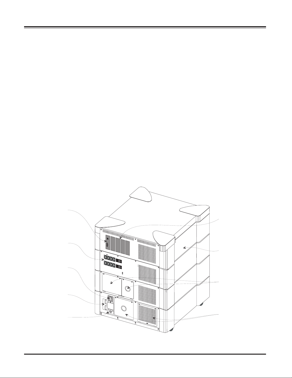
The rear of a MiniFrame Power Array system is shown below. (The rear of a MasterFrame is identical.) Each of the
components is described in a section that follows:
iew of a Power Ariew of a Power Ar
iew of a Power Ar
iew of a Power Ariew of a Power Ar
rayray
ray
rayray
System Enable Switch
The system enable switch regulates power to the intelligence
modules. It does not power the load. When switched to the
on position, the Power Array enters the load-disconnect
operating mode. When switched to stand by, the intelligence modules are disconnected from the mains voltage, and
the system shuts down.
Note : The load is not powered until the power the load command is entered into the PowerView user interface.
Communication Interface Ports
There are three interface ports: A Remote PowerView port
for the 6.1 m (20') RJ45 PowerView cable, a 9-pin computer
interface port for APC PowerChute Plus software, and a battery communication port for an XR Extended Run Frame.
Smart Slots
APC manufactures a set of auxiliary user interface accessories, called SmartSlot
TM
Accessory Ports
TM
devices. Four SmartSlotTM installa-
tion ports are provided. SmartSlotTM interface options include
the following:
n Protection and safe shutdown of multiple servers
n SNMP adaptor for accessing data via a network
n CallUPSTM - telephone notification of power event
n MeasureUPSTM - monitor environmental conditions
n Control and monitor Power Array via modem
Note: Use only SmartSlot
Compatible.
TM
devices labeled Symmetra
TM
REPO/Input/Output Wiring Access Panels
Wiring terminal blocks for input and output wiring and for
remote emergency power off (REPO) switch installations are
accessed through these panels.
Note: Wiring is to be installed by a qualified electrician only.
Convenience Power Panel
Eight IEC 320 C13 type power outlets are provided. The outlets are arranged in two sets of four. Each set is equipped with
a circuit breaker.
Extended Run Battery Frame Connector
An optional XR Extended Run Battery Frame can be connected
to the Power Array via this connector. See the Users Manual
included with the XR Extended Run Battery Frame.
Communication
Interface
Ports
Convenience Power
Panel
System
Enable
Switch
XR Extended Run
Battery Frame
Connector
REPO Wiring
Access Panels
SmartSlot
Accessory
Ports
MiniFrame
Output
Wiring
Access
Panels
Input
Wiring
Access
Panels
TM
1-4
Fig 1-10 Rear View of a Mini Frame SymmetraTM Power Array System
Page 22
Chapter Two
Site Preparation
This chapter provides the environmental and
structural requirements for a SymmetraTM Power
Array system. Included are the weights, dimen-
sions, and heat output of a functioning system.
MiniFrame
MasterFrame
Page 23
Chapter 2 - Site Preparation
Space and WSpace and W
Space and W
Space and WSpace and W
The Power Array frame is 61cm (24") wide and 68.6cm (27")
deep. Refer to table 4-1 for the height and weight of fully
loaded systems.
Table 2-1 Height & Weight (Loaded w/ Modules)
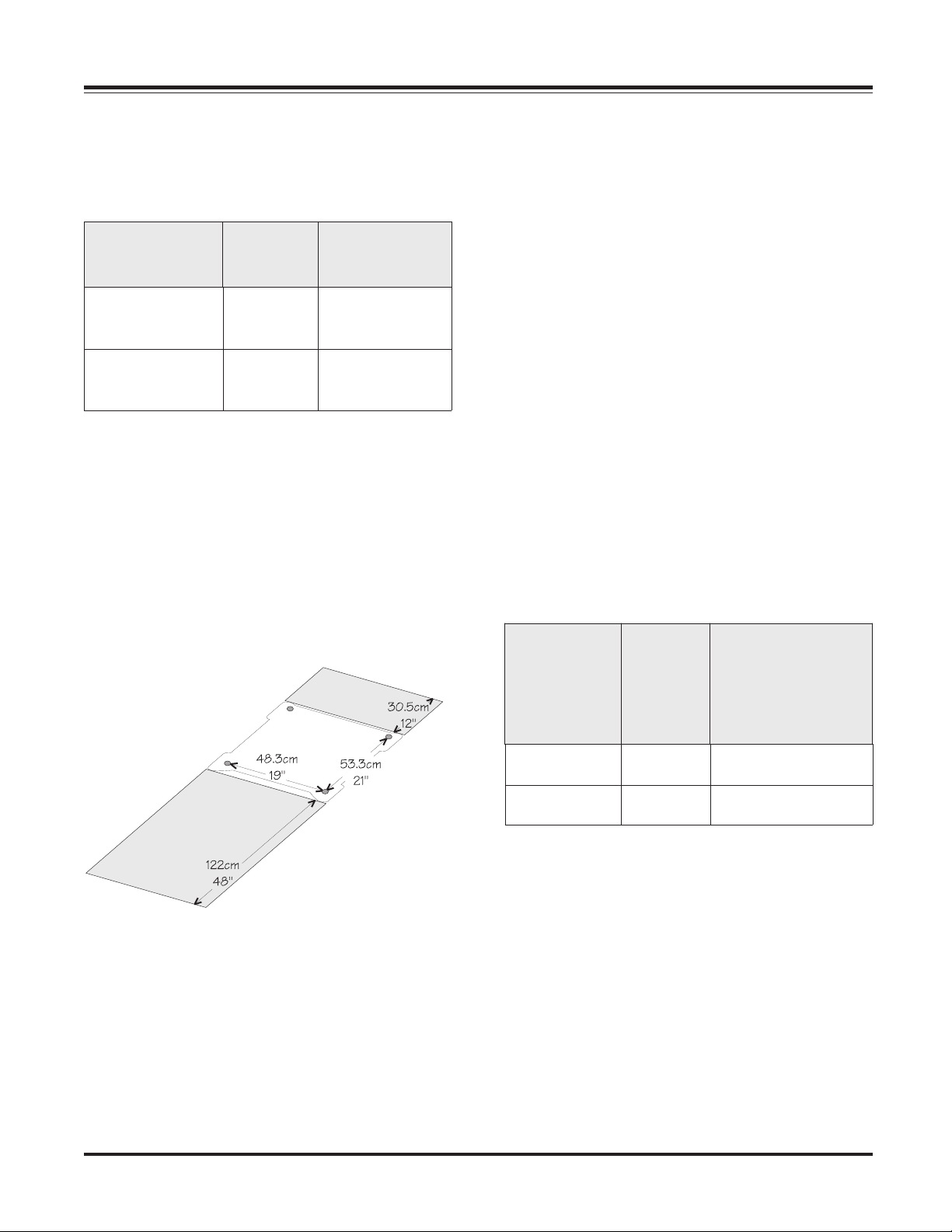
Make sure there is adequate space and structural integrity to
support the fully loaded frame. Refer to figure 2-1. The weight
of the Power Array rests on four 3.8cm (1.5") diameter leveling
feet. Positions of the leveling feet are shown. When installing
the frame, allow 30.5cm (12") of clearance behind the frame
for adequate airflow. (Air flows in through the front of the
frame and out the back.) Allow 122cm (48") of clearance in
the front of the SymmetraTM to access the PowerView and to
install modules.
eight Considerationseight Considerations
eight Considerations
eight Considerationseight Considerations
eziSemarFeziSemarF
eziSemarFeziSemarF thgieHthgieH
eziSemarF
emarFiniM
emarFretsaM
mc7.87
"13
"25
thgieHthgieH
thgieH
mc1.231
Rear
Clearance
thgieWthgieW
thgieWthgieW
thgieW
dedaoLylluFdedaoLylluF
dedaoLylluFdedaoLylluF
dedaoLylluF
gk832
bl525
gk914
bl529
Operating Conditions
The Power Array is intended for installation in a temperature
controlled indoor area that is free of conductive contaminants.
The operating evironment must be clean, dry, and protected.
The atmosphere must be free of dust and corrosive fumes.
Adequate airflow must be provided for the operation of the
system. Make sure environmental conditions are within the
following parameters:
n Relative Humidity: 0 to 95%, non-condensing.
n Temperature: 0°C to 40°C (32°F to 104°F).
n Elevation: 0m to 3,048m (0ft to 10,000ft).
n Electro-Static Discharge (ESD) Susceptibility: The Power
Array and all modules are capable of withstanding
through air electro-static discharges up to an amplitude of +/-15kV and direct discharge electro-static discharges up to an amplitude of +/-8kV without failure,
abnormal operation, or degradation in performance. ESD
test methods conform to IEC 801-2.
BTU Output
Refer to table 2-2 for BTU output of a fully loaded Power
Array system. The BTU output is significantly higher while
the batteries are charging. Under normal operating conditions, battery recharge periods are relatively infrequent.
rH/UTBrH/UTB
rH/UTBrH/UTB
rH/UTBrH/UTB
rH/UTBrH/UTB
rH/UTB
emarFemarF
emarFemarF
emarF
eziSeziS
eziSeziS
eziS
(((((
yllufylluf
yllufylluf
ylluf
(((((
seirettabseirettab
seirettabseirettab
seirettab
)degrahc)degrahc
)degrahc)degrahc
)degrahc
rH/UTB
,gnigrahcseirettab,gnigrahcseirettab
,gnigrahcseirettab,gnigrahcseirettab
,gnigrahcseirettab
yticapacemarfllufyticapacemarflluf
yticapacemarfllufyticapacemarflluf
yticapacemarflluf
eludom1+Nhtiweludom1+Nhtiw
eludom1+Nhtiweludom1+Nhtiw
eludom1+Nhtiw
)noitarugifnoc)noitarugifnoc
)noitarugifnoc)noitarugifnoc
)noitarugifnoc
Front Clearance
Fig 2-1 System Footprint and Required Clearance
Transporting Power Array to Installation Site
When it is shipped, the Power Array frame is bolted to a custom-designed pallet. The modules are stacked on either one
or two additional pallets. It is recommended that these pallets
be moved from the receiving dock to the installation area with
a pallet jack. Make sure there is enough space and structural
integrity to move these pallets.
emarFiniM314,3076,8
emarFretsaM628,6046,51
Table 2-2 BTU Output
Temporary Storage of Modules
The battery and power modules must be temporarily stored
until the frame is permanently installed. To preserve battery
life, always store batteries in a cool, dry place.
2-1
Page 24

Chapter 2 - Site Preparation
2-2
Page 25

Chapter Three
Unpacking and Installing Frame
This chapter provides the procedures for inspect-
ing the SymmetraTM frame and modules when
they arrive. It includes procedures for moving the
frame and modules to the installation site and
for removing them from the pallet.
MiniFrame
MasterFrame
Page 26

Chapter 3 - Unpacking and Installing Frame
Initial InspectionInitial Inspection
Initial Inspection
Initial InspectionInitial Inspection
The SymmetraTM Power Array system is shipped on pallets.
The system frame is bolted to one pallet, and the modules are
boxed and stacked on one or two additional pallets.
Check For Damage
1. Inspect the Packaging - for damage or signs of mishandling before moving the pallets. If damage is detected, note it
on the Bill of Lading.
2. If Any Damage Is Detected - file a damage claim with the
shipping agency within 24 hours. Inform APC of the damage
claim and the condition of the equipment.
3. System Administrator- make sure the system administrator participates in the initial inspection.
snoisnemiDsnoisnemiD
snoisnemiDsnoisnemiD
MTMTMTMTMT
artemmySartemmyS
artemmySartemmyS
artemmyS
tnenopmoCtnenopmoC
tnenopmoCtnenopmoC
tnenopmoC
6
emarFiniM
emarFretsaM
x1
16
6x
(
snoisnemiD
mcHxDxW
)sehcni(
6.86
x
7.87
)"13x"72x"42(
6.8
x
1.231
)"25x"72x"42
thgieWthgieW
thgieWthgieW
thgieW
)bl(gk
gk631
(
bl003
)
gk632
(
bl025
)
Move the FrameMove the Frame
Move the Frame
Move the FrameMove the Frame
1. Plan the Route - Make sure all passages are large enough to
accommodate the frame and the pallet jack. Check to see that
the floor has sufficient strength. See Table 3-1 for weights and
dimensions. Check doorways, elevators, ramps, etc, to insure
there are no non-negotiable corners, step-ups, or offsets. Select a route that provides the smoothest possible floor surface.
2. Staging Area - A smooth, level floor surface is required to
position the frame pallet, to remove the packaging materials,
and to install the ramp. It must provide adequate space for
two people to carefully roll the frame down the ramp and onto
the floor. See Figure 3-1 below for staging area dimensions.
3. Using the Pallet Jack - Carefully move the frame to the
staging area.
Pallet Jack
Frame
on Pallet
Ramp
Floor
Staging
Area
yrettaB
eludoM
eludoMrewoP
Table 3-1 Dimensions and Weights
9.22
5x
.0
(
4.52
x
8.05
(
2.51x8
)"6x"02x"9
x
2.51
"6x"02x"01
)
gk82
(
bl06
)
gk61
(
bl53
)
Handling Considerations
1. The Frame Pallet - See Table 3-1 for frame weight and
dimensions. Before removing shipping materials, the frame
and pallet should be positioned as closely as possible to the
installation site. The frame is bolted to the pallet. It is removed from the pallet using a ramp that is included. Use a
pallet jack to position the frame pallet.
Note: Do not attempt to move the frame with a hand dolley.
2. The Modules Pallet - Position the modules pallet(s) as
closely as possible to the final installation site with the pallet
jack. If this is not possible, remove the outer packaging materials and carry each individual, boxed module to the installation site.
Fig 3-1 Staging Area
3-1
Page 27

Chapter 3 - Unpacking and Installing Frame
Remove Packing MaterialsRemove Packing Materials
Remove Packing Materials
Remove Packing MaterialsRemove Packing Materials
Note: Temporarily store all packaging materials in case any of
the system components must be returned to APC.
1. Remove the Shipping Bands - Using appropriate precautions, cut the plastic shipping bands.
2. Remove the Cardboard - Using care not to damage the
surface of the Power Array, remove the cardboard from the
frame. Save the electrical installation instructions that are
printed on the packaging material.
3. The Pallet Ramp - The pallet ramp is shipped under the
cardboard cap on top of the frame. Cautiously remove the
ramp from the top of the frame.
4. Remove the Cover Grills - Remove the grill covers from the
frame. Grasp a grill cover by the side finger hold, and pull
straight forward. Set the covers to one side. Do not scratch
them.
5. Leveling Feet - Fully retract each of the four leveling feet
located near the casters on the bottom of the frame.
Frame
Restraint
Remove the Frame frRemove the Frame fr
Remove the Frame fr
Remove the Frame frRemove the Frame fr
1. Loosen Rear Bracket Screws - Loosen the two phillipshead screws securing the brackets at the rear of the frame.
2. Remove Two Frame Restraint Screws - See Figure 3-2.
Remove the frame restraint screws. Use the cloth handle to
remove the frame restraint from the pallet. Place the frame
restraint and two screws aside.
3. Install the Ramp - Position the ramp so that the installation
bolts line up with the ramp bolt holes on the pallet. Install the
ramp onto the pallet as shown in Figure 3-3.
om the Palletom the Pallet
om the Pallet
om the Palletom the Pallet
Ramp
Holes
Fig 3-2 Frame Restraint and Ramp Holes
Fig 3-3 Frame Pallet Ramp
4. Roll the Frame from the Pallet - The following operation
requires two people. Holding the frame near the center, care-
fully roll it down the ramp and onto the floor. (The frame is
equipped with casters.)
5. Roll the Frame to the Installation Site - Carefully roll the
frame from the staging area to the final installation site.
6. Shipping Material Storage - Gather and store all shipping
materials.
Moving Battery & Power ModulesMoving Battery & Power Modules
Moving Battery & Power Modules
Moving Battery & Power ModulesMoving Battery & Power Modules
1. Move Battery and Power Modules On Pallet - Use the
pallet jack to move the modules pallet(s) to the installation
site. Remove the outer packaging materials.
2. Stack Modules - Carefully stack the boxed battery and
power modules near the installation site. Leave adequate space
for the electrican to install wiring to the frame.
3-2
Page 28

Chapter Four
Wiring Requirements & Procedures
This chapter is addressed to the qualified
electrican who will install the input, output
and remote emergency power off hardwiring
connections. Circuit requirements and
minimum wire gauges are included.
MiniFrame
MasterFrame
Page 29

SymmetraTM Wiring
n All power and control wiring must be installed by a
qualified electrician only. All input, output, and
emergency power off wiring must comply with applicable local and country codes.
n Use flexible metal conduit when hardwiring the Power
Array. This will provide for ease of service and maintenance of the system.
There are three categories of hardwiring installation procedures for the SymmetraTM Power Array:
n Input Wiring
n Output Wiring
n Remote Emergency Power Off Switch Wiring
Input Wiring
Chapter 4 - Electrical Requirements and Procedures
The Power Array requires a single phase 220V, 230V, or 240V
incoming AC mains (utility) power source. Incoming power
is wired directly to a terminal block inside the Power Array.
Input wiring specifications and installation procedures are
provided.
Output Wiring
Power is distributed to the load equipment via hardwired connections from an output terminal block inside the Power Array frame and/or by plugging the load equipment into the
convenience power panel. With the PowerView user interface, the Power Array can be configured to deliver either 220V,
230V, or 240V. Output wiring specifications and installation
procedures are provided.
REPO Switch Wiring
The SymmetraTM Power Array can be connected to either a
dry contact or a 24Vdc remote emergency power off (REPO)
switch. The wiring terminal connections for the REPO are
physically isolated from the primary circuitry of the Power
Array. Wiring specifications and installation procedures for
REPO wiring are provided.
4-1
Page 30

Chapter 4 - Electrical Requirements and Procedures
Input Wiring
n Read this chapter completely before installing wiring.
n Verify that all incoming line voltage (mains power)
and low voltage (control) circuits are de-energized and
locked out before installing cables or making connections, whether in the junction box or to the
SymmetraTM Power Array.
n Always verify that all battery modules are removed
and all battery extension frames are disconnected from
the Power Array before installing wiring.
Input Wiring SpecificationsInput Wiring Specifications
Input Wiring Specifications
Input Wiring SpecificationsInput Wiring Specifications
The Power Array requires a single phase 220V, 230V, or 240V
50 or 60Hz incoming utility (mains) power source. A 3-conductor cable (2 live, 1 ground) is to be brought to two input
wiring terminal blocks inside an adequate length of flexible
metal conduit. To minimize disturbances caused by other
loads in the building, input wiring should be supplied directly from the service entrance (a dedicated power feeder).
All electrical service, both input and output, must be sized in
accordance with local building codes. The circuit for input
power must be adequate to carry the full load of the system
and the load equipment. The 3-conductor input cable should
be sized for no more than 3% voltage drop.
A 20 mm (3/4") knockout in the input wiring access panel
provides access to the terminal blocks.
See table 4-1 for input wiring specifications.
Input WInput W
Input W
Input WInput W
1. Refer to figure 4-1. Locate the input wiring entry and
input wiring inspection panels at the rear of the frame.
2. Remove the four screws securing the panels to the frame.
Remove only the screws indicated in the illustration. Place
the screws and panels aside.
3. Pull the input wires through an adequate length of 20 mm
(3/4") flexible metal conduit, leaving about 51.3 cm (20") of
wiring extending from the end. Install a flexible metal conduit connector to the end of the conduit. Using appropriate
tools, remove the knockout in the entry panel. Feed the wires
through the entry panel, and attach the flexible metal conduit connector to the panel.
4. Strip 13mm (1/2") of insulation from the end of each of
the incoming wires.
5. Note the positions of the ground wiring terminal block
and the input wiring terminal block. See figure 4-2.
iring Priring Pr
iring Pr
iring Priring Pr
Fig 4-1 Removal of Input Hardwiring Panels
ocedurocedur
ocedur
ocedurocedur
Entry Panel
eses
es
eses
4-2
emarFemarF
emarFemarF
tupnItupnI
tupnItupnI
tupnI
egatloVegatloV
egatloVegatloV
egatloV
sulperiw-2(sulperiw-2(
sulperiw-2(sulperiw-2(
sulperiw-2(
)dnuorg)dnuorg
)dnuorg)dnuorg
)dnuorg
caV032,caV022
caV042ro
emarF
eziSeziS
eziSeziS
eziS
AVk.xaM(AVk.xaM(
AVk.xaM(AVk.xaM(
AVk.xaM(
)gnitaR)gnitaR
)gnitaR)gnitaR
)gnitaR
)AVk8(iniM
)AVk61(retsaM
Table 4-1 Input Wiring Specifications
lluFtupnIlluFtupnI
lluFtupnIlluFtupnI
lluFtupnI
daoLdaoL
daoLdaoL
daoL
egarepmAegarepmA
egarepmAegarepmA
egarepmA
pmA53
pmA07
tupnItupnI
tupnItupnI
tupnI
&tupnImuminiM&tupnImuminiM
tnerrucrevOtnerrucrevO
tnerrucrevOtnerrucrevO
tnerrucrevO
noitcetorPnoitcetorP
noitcetorPnoitcetorP
noitcetorP
)lanretxE()lanretxE(
)lanretxE()lanretxE(
)lanretxE(
pmA05
pmA001
&tupnImuminiM&tupnImuminiM
&tupnImuminiM
eguaGeriWdnuorGeguaGeriWdnuorG
eguaGeriWdnuorGeguaGeriWdnuorG
eguaGeriWdnuorG
)mm462,3(eguaG8#
)mm981,5(eguaG4#
Page 31

Ground Wiring Terminal Block
Chapter 4 - Electrical Requirements and Procedures
Fig
Input Wiring Terminal Block
Fig 4-2 Ground Wiring and Input Wiring Terminal Blocks
6. Connect the ground wire to the ground wiring terminal
block. See figure 4-3. Make sure there are no loose strands
and the terminal connection screw is sufficiently tightened.
Input Ground Wire
Existing Wiring
Fig 4-3 Ground Hardwiring Connection
7. Feed the L1 and Neutral wires through the wiring pathway
hole to the input wiring terminal block. See figure 4-4 for
the input wiring pathway.
4-4 Input Wiring Pathway
8. Connect input wires to the input terminal block connections labeled L1 and N as shown in figure 4-5. Make sure
there are no loose strands and that the terminal connection
screws are sufficiently tightened.
L1 Wire
Neutral Wire
Existing Wiring
Fig 4-5 Input Hardwiring Connections
9. Carefully fold the excess wiring into the entry compartment. After the electrical wiring test/checklist at the end of
this chapter is completed, replace the input wiring panels.
4-3
Page 32

Chapter 4 - Electrical Requirements and Procedures
Output Wiring
n Read this chapter completely before installing wiring.
n Verify that all incoming line voltage (mains power)
and low voltage (control) circuits are de-energized and
locked out before installing cables or making connections, whether in the junction box or to the
SymmetraTM Power Array.
n Always verify that all battery modules are removed
and all battery extension frames are disconnected from
the Power Array before installing wiring.
Output voltage is delivered to the load equipment via
hardwired connections and/or via eight IEC 320 C13 power
outlets at the rear of the Power Array. To facilitate maintenance and service of the Power Array, use flexible metal conduit for all hardwiring connections.
See table 4-2 for output wiring specifications.
Output Wiring InstallationOutput Wiring Installation
Output Wiring Installation
Output Wiring InstallationOutput Wiring Installation
1. Refer to Fig 4-6. Remove the four screws holding the output wiring entry panels to the rear of the Power Array. Remove only the screws indicated in the illustration. Set the
screws and both panels aside temporarily.
2. Pull the L1, Neutral, and Ground wires through conduit,
leaving about 51.3 cm (20") of wiring extending from the
end. Install a flexible metal conduit connector to the end of
the conduit. Using appropriate tools, remove the knockout
in the entry panel. Feed the wires through the entry panel,
and attach the flexible metal conduit connector to the panel.
Strip 13 mm (1/2") of insulation from the end of each of the
incoming wires.
3. Connect output wiring to the output terminal connections as shown in figure 4-7. Make sure there are no loose
strands and that the terminal connection screws are sufficiently tightened.
L1 Wire Connection
Fig. 4-6 Removal of Output Hardwiring Panels
emarFemarF
emarFemarF
tuptuOtuptuO
tuptuOtuptuO
tuptuO
egatloVegatloV
egatloVegatloV
egatloV
)dnuorg+seriw-2(
emarF
eziSeziS
eziSeziS
eziS
AVk.xaM(AVk.xaM(
AVk.xaM(AVk.xaM(
AVk.xaM(
)gnitaR)gnitaR
)gnitaR)gnitaR
)gnitaR
Neutral Wire
Connection
Ground Wire
Connection
Fig. 4-7 Output Hardwiring Connections
4. Carefully fold the excess wiring into the entry compartment. After the electrical wiring test/checklist at the end of
this chapter is completed, replace the input wiring panels.
tuptuOtuptuO
tuptuOtuptuO
mumixaMmumixaM
mumixaMmumixaM
mumixaM
rePtuptuOrePtuptuO
rePtuptuOrePtuptuO
rePtuptuO
rotcudnoCrotcudnoC
rotcudnoCrotcudnoC
rotcudnoC
tuptuO
tnerrucrevOtnerrucrevO
tnerrucrevOtnerrucrevO
tnerrucrevO
noitcetorPnoitcetorP
noitcetorPnoitcetorP
noitcetorP
)lanretxE()lanretxE(
)lanretxE()lanretxE(
)lanretxE(
&tuptuOmuminiM&tuptuOmuminiM
&tuptuOmuminiM&tuptuOmuminiM
&tuptuOmuminiM
eguaGeriWdnuorGeguaGeriWdnuorG
eguaGeriWdnuorGeguaGeriWdnuorG
eguaGeriWdnuorG
4-4
,caV032,caV022
caV042ro
)AVk8(iniM
)AVk61(retsaM
Table 4-2 Output Wiring Specifications
pmA04
pmA08
)elop-2(pmA05
)elop-2(pmA09
)mm462,3(eguaG8#
)mm981,5(eguaG4#
Page 33

Remote Emergency Power
Off Switch
Chapter 4 - Electrical Requirements and Procedures
REPO Switch InstallationREPO Switch Installation
REPO Switch Installation
REPO Switch InstallationREPO Switch Installation
The Power Array can be de-energized with a remote emergency power off (REPO) switch. REPO switches are common in computer rooms where, for safety reasons, power to
the loads must be quickly disconnected. The REPO switch
physically flips the system enable switch to stand by mode.
This cuts power to the main intelligence module, which in
turn cuts power to the Power Array and to the load equipment. The system enable switch must be physically reset.
IMPORTANT: The system enable switch cuts power to the intelligence module only. All internal circuitry that is connected
to incoming utility (mains) voltage is still powered if incoming
utility power is still present.
The REPO can be connected to either a switched, 24Vdc circuit, or a simple contact closure.
REPO SpecificationsREPO Specifications
REPO Specifications
REPO SpecificationsREPO Specifications
The REPO circuit is considered a Class 2 and SELV circuit.
SELV is an acronym for Safety Extra Low Voltage. SELV is a
common term in Europe and IEC standards. A SELV circuit
is isolated from primary circuitry through an isolating transformer and designed so that under normal conditions, the
voltage is limited to 42.4 Vpeak or 60 Vdc.
A Class 2 Circuit is a common term in North America and in
UL and CSA standards. It is defined in the Canadian Electrical Code (C22.1, Section 16) and in the National Electrical
Code (NFPA 70, Article 725).
SELV and Class 2 circuits must be isolated from all primary
circuitry. Do not connect any circuit to the EPO terminal
block unless it can be confirmed that the circuit is SELV or
Class 2. If there is a question, use a contact closure switch.
n Verify that all incoming line voltage (mains power)
and low voltage (control) circuits are de-energized and
locked out before installing cables or making connections, whether in the junction box or to the
SymmetraTM Power Array.
n Always verify that all battery modules are removed
and all battery extension frames are disconnected from
the Power Array before installing any wiring to the
Power Array.
REPO Wiring Procedures
1. Refer to figure 4-8. Remove the screw holding the twopiece access panel at the rear of the Power Array. Remove the
panel. Set the screw and the panel pieces aside.
Cable Specifications
The cable that connects SymmetraTM to the Emergency Power
Off switch should be one of the following UL Listed types:
CL2 - Class 2 cable for general purpose use; or
CL2P - Plenum cable for use in ducts, plenums, and other
space used for environmental air; or
CL2R - Riser cable for use in a vertical run in a shaft or from
floor to floor; or
CL2X - Limited Use cable for use in dwellings and for use in
raceway.
For installation in Canada, the cable should be CSA Certi-
fied, type ELC (Extra-Low-Voltage Control Cable).
Fig 4-8 Removal of REPO Wiring Panels
2. Refer to figures 4-9 and 4-10. Select the configuration that
matches the type of REPO switch that is to be installed.
Note: An existing jumper must be removed from the terminal
block if a 24Vdc REPO switch (figure 4-10) is to be installed.
3. Extend the wiring from the switch to the Power Array. Strip
13 mm (1/2") of insulation from the end of each of the incoming wires.
4. Feed the wires through the knockout in the access panel,
and install a strain relief (Romex) connector.
5. Make sure there are no loose strands and that the terminal
connection screws are sufficiently tightened.
6. After the electrical wiring test/checklist at the end of this
chapter is completed, replace the REPO access panel.
4-5
Page 34

Chapter 4 - Electrical Requirements and Procedures
Contact Closure REPO Switch Connection
Connect the contact closure REPO wiring to the terminal
block as illustrated in figure 4-9 below.
Note : The factory installed jumper remains as shown.
Jumper Installed
Fig 4-9 Dry Contact Switch
24 Vdc REPO Switch Connection
Connect the 24Vdc REPO wiring to the terminal block as
illustrated in figure 4-10 below.
Note : The factory installed jumper must be removed.
Electrical Wiring Test
The following test procedure will ensure that the Power Array has been correctly hardwired. The qualified electrician
who installed the Power Array should perform this test. A
true RMS voltmeter and a ground ohmmeter are required.
Before this test can be conducted, the main intelligence module (MIM) must be installed, and the PowerView display must
be connected to the Power Array. Refer to Chapter 5 for procedures to install the MIM and the PowerView.
IMPORTANT: Make sure the power modules and the battery
modules ARE NOT installed for this test.
Note: This test is intended to verify the electrical connection to
the Power Array, not to verify its operation or explain its usage.
In this procedure, you will be instructed to ignore PowerView
messages, etc. Refer to Chapters 6 & 7 for detailed information
about the operation of the Power Array.
Electrical WElectrical W
Electrical W
Electrical WElectrical W
q 1. Make sure all three switches -- system enable, mainte-
nance bypass, and input circuit breaker -- are in the off
or stand by position.
IMPORTANT: Make sure all load equipment is either
turned off or is unplugged from the Power Array.
q 2. Use a true RMS voltmeter to measure the input AC
utility (mains) voltagte to the terminal connections at
the rear of the frame (bottom level).
Note: If input voltage is less than 156Vrms or greater than
276Vrms, check input wiring for errors. DO NOT PROCEED UNTIL THE INPUT VOLTAGE IS WITHIN THIS
RANGE.
iring Tiring T
iring T
iring Tiring T
est/Checklistest/Checklist
est/Checklist
est/Checklistest/Checklist
4-6
Fig 4-10 24Vdc EPO Switch
24Vdc
Power
Source
Record the input voltage here: ____________________
q 3. Check for proper ground installation with a ground
ohmmeter. Check for continuity to building ground.
q 4. Switch the input circuit breaker to the on position.
q 5. Switch the system enable switch to the on position.
Note: The Power Array may make a series of clicking sounds
as it runs through an initial self test.
Page 35

Chapter 4 - Electrical Requirements and Procedures
q 6. Using the PowerView display, read and record the re-
ported input voltage from the startup screen. (220Vin
in figure 4-11 indicates that the input voltage is 220V.)
Note: The PowerView may display one or more messages
such as Number of Battery Modules Changed. Press the
ESC key until the startup screen appears.
Record the PowerView reported
input voltage here: ______________________________
Fig 4-11 Startup Screen
q 7. Compare the RMS input voltage measurement (Step
#2) with the input voltage as reported by the PowerView.
If the two measurements are significantly different, contact APC SymmetraTM technical support.
q 9. Measure the output AC voltage at the output wiring
terminal block. If the measured output voltage varies
significantly from the actual input voltage, or from the
output voltage reported by the PowerView, contact
SymmetraTM technical support.
q 10. Successful completion of steps 1 through 9 indicates
the Power Array is correctly wired to the utility power
source and that the correct output voltage is available at
the output terminal block. Load equipment voltage requirements and external wiring voltages should be
checked and verified at this time.
q 11. Shut down the Power Array by switching the input
circuit breaker and the system enable switch to the off
position. Replace all wiring access panels on the Power
Array frame. The electrical connections have now been
properly installed and checked. The Power Array is now
ready for the setup procedure in Chapter 5.
q 8. Switch the maintenance bypass switch to the on po-
sition. The Power Array will go into the manual bypass
mode, and voltage should now be present at the output
terminal connections. The bypass LED on the
PowerView display will glow and one or more messages
may appear on the PowerView display. Ignore these messages by pressing the ESC navigation key on the
PowerView display until the startup screen reappears. See
figure 4-11. Read and record the output voltage that is
indicated on the PowerView. (000Vout in figure 4-11
indicates that the output voltage is 000V.)
Note : The reported output voltage should be approximately
220V, 230V, or 240V, depending on how the system is configured.
Record the PowerView reported
output voltage here: _____________________________
4-7
Page 36

Chapter Five
Setting Up The Power Array
This chapter provides the procedures for
leveling the frame, installing the battery and
power modules, and connecting the PowerView.
An installation test is provided at the end of
this chapter. Follow these steps to ensure
that the system is properly installed and ready
to supply conditioned power to load equipment.
MiniFrame
MasterFrame
Page 37

Chapter 5 - System Setup
Setup of Power ArraySetup of Power Array
Setup of Power Array
Setup of Power ArraySetup of Power Array
After the input and output wiring has been properly connected and checked by a qualified electrican, the Power Array is ready for the installation of the battery and power modules. After they are installed, the grill covers are replaced onto
the frame, and the PowerView user interface is mounted onto
the frame.
Frame Leveling Procedure
Position the Power Array so there will be adequate airflow
clearance in the front and the rear of the frame. See figure 5-
1. The weight of the Power Array is supported by four 3.8cm
(1.5") leveling feet pads. Four metal plates can be placed under
each of the leveling feet pads to help displace the weight of
the Power Array.
The procedure for leveling the frame is as follows:
1. Hand turn all four leveling feet until the pads make contact with the floor.
2. Use an open-end wrench to extend each of the leveling
feet by turning the hex nut three complete revolutions.
3. Adjust the leveling feet until the frame is level front to
back and side to side.
Rear
Clearance
Leveling Feet
Positions
30.5cm
12"
Removing Grill Covers
The grill covers must be removed before the power and battery modules can be installed.
Note: Handle grill covers with care to prevent scratching them.
1. Grasp one of the covers by the side holds. See figure 5-2.
2. Pull the cover straight forward. The cover unsnaps from
the frame.
3. Remove all grill covers.
4. Place them safely to one side.
48.3cm
19"
Front Clearance
122cm
48"
Fig 5-1 The Power Array Four Leveling Feet
53.3cm
21"
Fig 5-2 Removing Grill Covers from Frame
5-1
Page 38

Chapter 5 - System Setup
Installing the BatterInstalling the Batter
Installing the Batter
Installing the BatterInstalling the Batter
The vertical column of bays at the right side of the Power
Array frame houses the battery modules. See Figure 5-3.
n Each battery module weighs 27kg (60 lb). Battery
module installation and handling requires two people.
n The PowerView cable must be held out of the way while
a battery module is installed in bay R2.
y Modulesy Modules
y Modules
y Modulesy Modules
Procedure for Battery Module Installation
1. Clear all battery module bays of any debris.
Battery
Module
Bays
1-Alignment Grooves, 2-Retaining Notch,
3-Battery Module Retaining Flange, 4-Runners
Fig 5-4 Battery Alignment Grooves and Runners
Note: As the battery module slides into the bay, a retaining flange
will fall behind a notch in the frame. See figure 5-5. This is a
safety feature. When the battery module is removed from the
frame, this flange prevents the battery from falling out of the
bay until both people have assumed the full weight of the module.
Battery
Module
Fig 5-3 Location of Battery Module Bays
Note: There are two alignment grooves molded into each bat-
tery module bay. These correspond with runners on the bottom
of each battery module. See figure 5-4.
2. With one person on either side of the battery module, lift
the module, align the runners with the alignment grooves,
and slide the module into a bay. Always install power or battery modules in the lowest available bays. Installing them in
this manner minimizes lifting and lowers the center of gravity of the Power Array system.
Fig 5-5 Battery Module Retaining Flange
3. Engage the internal electrical connector by swiftly and
firmly pushing the battery module into place. The battery
module design incorporates a drop lock that engages when
the battery module is properly seated in the bay. If this lock
does not engage, a slight tug will move the module. When it
is locked, the battery module sits firmly in place and must be
lifted slightly before it can be pulled from the bay.
5-2
Page 39

Chapter 5 - System Setup
Installing the Power ModulesInstalling the Power Modules
Installing the Power Modules
Installing the Power ModulesInstalling the Power Modules
The vertical column of bays at the left side of the Power Array frame houses the power modules. See Figure 5-6.
Procedure for Power Module Installation
1. Clear all power module bays of debris.
Power
Module
Bays
Power
Module
3. Slide the power module firmly into the bay to engage the
internal connector. The drop lock seating tabs will fall into
place. See figure 5-8.
Drop Lock
Seating Tabs
Fig 5-6 Location of the Power Module Bays
Note: There are two alignment grooves molded into each power
module bay. These correspond with runners on the bottom of
each power module. See figure 5-7.
2. Lift the power module, align the runners with the alignment grooves, and slide the module into a bay.
Alignment
Grooves
Runners
Fig 5-8 Seating Tabs When Module is Properly Installed.
4. Swing the flip latch up and gently tighten the captive screw
into the module. DO NOT overtighten this screw.
Note: The flip latch will not engage if the power module is not
fully seated into the bay. The flip latch activates a micro switch
inside the power module. If the latch is not properly installed,
the power module will not function. If the flip latch will not
engage, pull the power module partially out, and firmly slide it
back into place.
IMPORTANT!
Fig 5-7 Power Module Alignment Grooves and Runners
Fig 5-9 The Power Module Flip Latch
5-3
Page 40

Chapter 5 - System Setup
Installing the Main Intelligence ModuleInstalling the Main Intelligence Module
Installing the Main Intelligence Module
Installing the Main Intelligence ModuleInstalling the Main Intelligence Module
(MIM)(MIM)
(MIM)
(MIM)(MIM)
The main intelligence module is factory installed. The following procedure is provided in the event that the MIM is
removed or replaced:
Note: The main intelligence module is installed in the upper
right bay of the Power Array frame. The main intelligence module is always installed in the bottom rack in this bay, and the
redundant intelligence module is always installed in the top rack
in this bay.
1. Carefully align the installation rail on the MIM with the
track that runs along the inside of the bay.
2. Slide the MIM into the bay.
3. Tighten the two retaining screws. Do not overtighten.
4. Swing the flip latch into place, and tighten the screw. Do
not overtighten this screw. See figure 5-9.
Installing the Redundant IntelligenceInstalling the Redundant Intelligence
Installing the Redundant Intelligence
Installing the Redundant IntelligenceInstalling the Redundant Intelligence
Module (RIM)Module (RIM)
Module (RIM)
Module (RIM)Module (RIM)
The redundant intelligence module is factory installed. The
following procedure is provided in the event that the RIM is
removed or replaced:
Note: The redundant intelligence module is installed in the upper right bay of the Power Array frame. The redundant intelligence module is always installed in the top rack in this bay, and
the main intelligence module is always installed in the bottom
rack in this bay.
1. Carefully align the installation rail on the RIM with the
track that runs along the inside of the bay.
2. Slide the RIM into the bay.
3. Tighten the two retaining screws. Do not overtighten.
4. Swing the flip latch into place, and tighten the screw. Do
not overtighten this screw. See figure 5-9.
Fig 5-10 Location of the MIM and RIM
Redundant
Intelligence
Module
(RIM)
Main
Intelligence
Module
(MIM)
5-4
Page 41

Chapter 5 - System Setup
Installing the PowerVInstalling the PowerV
Installing the PowerV
Installing the PowerVInstalling the PowerV
A 61.5 cm (24") RJ45 cable is provided in the intelligence
modules bay. It is used to connect the PowerView to the Power
Array. Use the following procedure to install the PowerView
interface onto the frame:
1. Remove the grill cover from the top level of the frame.
2. Feed the end of the RJ45 cable through the center slot of
the grill cover. Replace the grill cover. See figure 5-11.
Fig 5-11 PowerView Cable Through The Top Grill Cover
3. Connect the RJ45 plug into the receptacle on the back of
the PowerView as shown in figure 5-12.
iew Interiew Inter
iew Inter
iew Interiew Inter
faceface
face
faceface
Fig 5-13 Install PowerView On The Frame
Remote Placement of the PowerView
Follow these steps to install the PowerView user interface in a
remote location:
Note: A 6.1m (20') Remote RJ45 cable is included with the
SymmetraTM Power Array.
1. Connect the Remote RJ45 cable to the communication
port at the rear of the Power Array frame. See figure 1-10.
2. Connect the other end of the cable to the receptacle at the
rear of the PowerView. See figure 5-12.
Note: The short length of RJ45 cable that is hardwired to the
Power Array frame can be safely coiled and placed on top of the
redundant intelligence module.
3. Replace the grill cover.
The PowerView can sit upright on a flat surface by folding
out the wire bail on the back. It can also be mounted onto a
wall.
Fig 5-12 Attach the Cable to the PowerView
5. Position the PowerView over the mounting post on the
front of the frame, and push straight down. The PowerView
snaps into place. See figure 5-13.
6. Tuck the excess cable into the grill cover.
Wall Mounting the PowerView
Follow these steps to install the PowerView on a wall:
1. Note the four mounting slots molded into the back of the
PowerView interface.
2. Use the template in figure 5-14 to secure four large screws
on a clean dry wall surface.
3. Leave the head of each screw 8mm (5/16") out from the
surface of the wall. Screws must be strong enough to support 6.8kg (15lb).
4. Mount the PowerView display onto the wall by positioning it over the screws and sliding it down until it is securely in
place.
5-5
Page 42

Chapter 5 - System Setup
Note: The PowerView can be configured to display English,
Spanish, German, French or Italian text. See chapter 6.
TMTM
TM
SmartSlotSmartSlot
SmartSlot
SmartSlotSmartSlot
TMTM
Interface Accessories Interface Accessories
Interface Accessories
Interface Accessories Interface Accessories
SmartSlotTM bays at the rear of the frame accommodate up to
four accessory cards. SmartSlot
TM
cards are available through
the dealer.
Note : APC offers a line of SmartSlot
TM
Accessories that are designed specifically to function with SymmetraTM. Before installing any SmartSlot
TM
accessory, make sure it is a Symmetra
TM
Compatible model.
n Share-UPS
TM
SmartSlotTM Accessory Card - Provides
automatic shutdown of up to two additional servers that
are connected to the Power Array.
9cm (3 1/2")
n PowerNet
TM
SNMP SmartSlotTM Accessory Card - Pro-
vides network UPS management.
n Measure-UPS
TM
II SmartSlotTM Accessory Card - Works
in conjuction with PowerNet SNMP and PowerChute
Plus software. Provides environmental information such
as ambient temperature and humidity.
Note: If installing more than one accessory card, always
install the Measure-UPS card in the slot that is all the way
to the right. (Slot #1.)
n Call-UPS
TM
SmartSlotTM Accessory Card - Works with
an external modem to provide out-of-band UPS management for the Power Array.
See the User's Manual included with the SmartSlot
TM
Acces-
sory card for specific installation and operating instructions.
5-6
10.3cm (4")
8cm (3 1/8")
Fig 5-14 PowerView Wall Mounting Template
Page 43

Chapter 5 - System Setup
Installation TInstallation T
Installation T
Installation TInstallation T
Note: This test is intended to verify the correct setup and installation of the SymmetraTM system. It is not intended to explain
its usage. In this procedure, you will be instructed to ignore
PowerView messages. Refer to chapters 6 & 7 for detailed information about the operation of SymmetraTM.
The following test procedure is intended to ensure that the
MIM, RIM and the power and battery modules have been
correctly installed. It will verify that the SymmetraTM is responding correctly and is ready to deliver power to the load
equipment. A qualified electrician and/or the installer of the
Symmetra
Before this test can be conducted, the main intelligence module (MIM), the PowerView display, at least one power module and at least one battery module must be properly installed.
Read the installation procedures provided in this chapter.
TM
estest
est
estest
system should perform this test.
Installation Test/Checklist
q 1. Make sure all three switches - system enable, mainte-
nance bypass, and input circuit breaker - are in the off or
standby position. Make sure all load equipment is either
turned off or is unplugged from the Symmetra
Note: Load equipment can be left connected during this test
procedure; however, power will be switched on and off to
the load equipment. Therefore, it is recommended that load
equipment be switched to the off position until the completion of this test.
TM
.
q 3. From the startup screen, press the ESC navigation
key to display the top level menu screen.
Fig 5-16 Top Level Menu & The Enter Navigation Key
Press the down arrow navigation key to select Status, and
then press the Enter navigation key. The voltage status
screen appears.
Fig 5-17 Voltage Status Screen
Read the voltage status screen to verify that input voltage (Vin)
is nominally either 220V, 230V or 240V. Verify that output
voltage (Vout) is approximately 0V.
q 4. Press the down arrow key to scroll to the frequency
status screen. See figure 5-18. Verfiy that the input frequency
is approximately 50 Hz.
q 2. Switch both the input circuit breaker and the system
enable switch to the on position. Symmetra
up internally but will not deliver output voltage. The
PowerView will display text. Depending on the configuration of the Symmetra
ber of Battery Modules has changed may appear. Press the
ESC navigation key until the startup screen appears. See
figure 5-15. Verify that the input voltage is 220V, 230V or
240V nominal, that the output voltage reads 000Vout, and
that all four of the PowerView LED indicator lights are off.
TM
, one or more messages such as Num-
Fig 5-15 Startup Screen
TM
will power
Fig 5-18 Frequency Status Screen
q 5. Press the down arrow key to the battery status screen.
Fig 5-19 Battery Status Screen
Verfiy the following:
q The number of battery modules reported (01 in the
example below) is the same as the actual number of
battery modules that are installed.
q The number of bad modules reported is zero.
q A minimum of 90V of battery voltage is reported.
Note: The reported battery voltage will vary from approximately
90V to 148V, depending on the state of the battery module
charge. If the reported voltage is less than 90V, allow the battery modules to recharge. (To recharge the battery modules,
leave the system enable switch and the input circuit breaker in
the on position, and allow the Power Array to remain idle for
30 minutes.)
5-7
Page 44

Chapter 5 - System Setup
q 6. Press the Down arrow key to scroll to the power mod-
ule status screen.
Fig 5-20 Power Module Status Screen
Verfiy the following:
q Total Pwr modules (power modules) reported is
the same as the actual number of power modules
that are installed.
q Bad power modules reported is 00 (zero).
q The first line of the power module status screen
displays the reported capacity of the SymmetraTM.
The reported capacity is based on the number of
power modules installed and the size of the frame.
See table 5-1 to confirm that the PowerView is
reporting the correct information.
rewoPrewoP
rewoPrewoP
rewoP
seludoMseludoM
seludoMseludoM
seludoM
dellatsnIdellatsnI
dellatsnIdellatsnI
dellatsnI
detropeRdetropeR
detropeRdetropeR
detropeR
niyticapaCniyticapaC
niyticapaCniyticapaC
niyticapaC
emarFiniMemarFiniM
emarFiniMemarFiniM
emarFiniM
detropeRdetropeR
detropeRdetropeR
detropeR
niyticapaCniyticapaC
niyticapaCniyticapaC
niyticapaC
emarFretsaMemarFretsaM
emarFretsaMemarFretsaM
emarFretsaM
q 8. Follow these steps to deliver output voltage to the
load equipment. See figure 5-22 for the screen sequence:
Note: It is recommended that load equipment be switched off
while this step is performed. After output voltage is delivered,
switch the load equipment on.
q Press the ESC key until the startup screen appears.
q Press the Enter key to display the top level menu.
q Press the Down key until the selection arrow points
to the Control menu item.
q Press the Enter key.
q Press the Down key, until the selection arrow
points to Turn Load ON.
q Press the Enter key.
q Confirm that you want to turn the load on, by
selecting YES, Turn UPS ON
q Several other over-ride messages may appear,
depending on the system configuration. Select Start
Now for any of these startup over-ride messages.
1AVk4AVk4
2AVk8AVk8
3AVk8AVk21
4a/nAVk61
5a/nAVk61
Table 5-1 SymmetraTM Power Module/Frame Capacities
q 7. Press the Down arrow key to scroll to the miscella-
neous status screen. The bottom line indicates the status of
the Main Intelligence Module (MIM) and the Redundant Intelligence Module (RIM). The sample screen in figure 5-21
indicates that both are installed and functioning properly
(OK). If a module is not installed, the status screen will display the word NONE. Confirm that the IM and RIM status
are correct. Use the ESC key to return to the startup screen.
Fig 5-21 Miscellaneous Status Screen
Fig 5-22 Power The Load Sequence
After several seconds, the PowerView display should report
that the UPS LOAD IS ON. Press the ESC key to return
to the startup screen. Confirm that output voltage is present
and that the Load On LED indicator is glowing.
Note: The Bypass LED indicator may flash on briefly, and the
On Battery LED indicator may glow for 20-30 seconds if the
system is configured for self test at power on.
q 9. Perform a self test by following the screen sequence in
figure 5-23.
Fig 5-23 Initiate a Self Test Sequence
The On Battery LED indicator should glow for approximately
30 seconds. A message will appear on the display indicating
that a self test is in progress. When the Self Test Complete
message appears, press any key to return to the startup screen.
5-8
Page 45

Chapter 5 - System Setup
q 10. Place the Symmetra
TM
into Bypass mode by follow-
ing the screen sequence in figure 5-24.
Fig 5-24 Initiate Bypass Mode
The Bypass LED indicator should glow, and the PowerView
display will indicate that the UPS (SymmetraTM) IS BYPASSED.
q 11. Return the Symmetra
TM
to the On-Line mode of op-
eration by following the screen sequence in figure 5-25.
Fig 5-25 Return to On-Line Mode
The Bypass LED indicator should cease to glow, and the message UPS IS OUT OF BYPASS will appear on the PowerView
display. Press any key to return to the startup screen.
q 12. Power down the load equipment by following the
screen sequence in figure 5-26.
Fig 5-26 Power Down the Load Sequence
From the Control menu, power down the load equipment by
executing the UPS LOAD OFF command. After several seconds, the UPS LOAD IS OFF message is displayed. All LED
indicators on the PowerView should be off.
q 13. Power down the Symmetra
tem enable switch and the input circuit breaker to the stand
by position. The installation procedure has now been completed.
TM
by switching the sys-
Note: This procedure is an installation checklist. Read and
follow the steps in Chapter 7 to configure the SymmetraTM Power
Array for your specific power needs.
5-9
Page 46

Chapter 5 - System Setup
5-10
Page 47

Chapter Six
PowerView Display
This chapter is an overview of the PowerView
user interface. The PowerView is used to
control the Power Array, configure function-
ality, monitor system components, set
alarm thresholds, and to compile and review
a log of power events. The PowerView pro-
vides the audible and visual alarms that are
initiated when an alarm event occurs.
The PowerView can display French, Italian,
German, Spanish or English text. Configura-
tion instructions are provided at the end of
this chapter.
MiniFrame
MasterFrame
Page 48

Chapter 6 - The PowerView Display
The PowerVThe PowerV
The PowerV
The PowerVThe PowerV
The PowerView is the primary user interface for the Power
Array system. It is used to control the Power Array, to configure the functionality, monitor the system, set alarm thresholds, and it provides audible and visual alarms for the system.
iew User Interiew User Inter
iew User Inter
iew User Interiew User Inter
faceface
face
faceface
Physical Features of the Powerview
The PowerView interface incorporates a 4 x 20 alphanumeric
liquid crystal display (LCD), four navigation keys, four light
emitting diode (LED) indicators, and an audible alarm beeper.
It is designed to either mount on the front of the frame, to
stand on top of the frame, or to be installed at a remote location up to 6.1m (20') away. A short RJ45 cable is hardwired
to the top right module bay of the frame. This cable connects to the PowerView when it is mounted onto the frame.
A 6.1m (20') RJ45 cable is provided for remote installation of
the PowerView.
PowerView Functions
An overview of each of the PowerView interface functions
are provided below:
n User Interface - The PowerView is used to command the
system to power up, and power down the load equipment, to review the status of modular and system components, and to configure functionality of the system.
n Alarms and Alarm Thresholds - In the event of a power
disturbance, or loss of a system component, (and other
user-configured alarm conditions), the PowerView interface emits both an audible alarm and displays a visual
message on the LCD screen*. Procedures for setting user
configurable parameters are provided in Chapter 7. All
PowerView display messages, and the corrective actions
are provided in Chapter 9.
n Set System Function Parameters - The PowerView can
be used to set parameters for the functioning of the Power
Array. These include acceptable input and output frequency ranges, frequency of self tests, and minimum/
maximum settings for power transfers.
Fig 6-1 The PowerView Interface
n PowerView Interface Parameters - The PowerView can
be used to set the contrast of the LCD screen, select the
information that is displayed in the startup screen, set
the time, date, password and the volume of the audible
alarm.
n Event Logging - The 64 most recent power and user
events are recorded and logged into the PowerView interface. The interface can be configured to log a specific
set or range of data. This data, as well as compiled statistics can be reviewed using the PowerView interface.
n Check Status and Diagnostics - Input voltage, output
voltage, available run time, load size, the present operating mode, and the status of every module in the Power
Array frame can be reviewed using the PowerView interface. (See Chapter 7.)
n Testing - The PowerView interface can be used to per-
form a system self test and to simulate a power failure.
n Help Function - Pressing the up and down navigation
keys simultaneously launches context sensitive help.
*For example, a Power Array with an N+1 redundancy can be
configured to emit an audible alarm if the system incurs the
lose of a redundant power module. (Typically, this would be
the result of additional load being added, or a power module
failure.)
6-1
Page 49

Chapter 6 - The PowerView Display
PowerVPowerV
PowerV
PowerVPowerV
Four LED indicators report the operational status of the Power
Array. Table 6-1 describes their function.
iew LED Indicatorsiew LED Indicators
iew LED Indicators
iew LED Indicatorsiew LED Indicators
DEL roloC noitpircseD
NODAOLneerG siyarrArewoPehtsetacidnI
enil-noehtnignitarepo
simetsysehT.edom
ehtmorfrewopgniviecer
sidna,ecruosrewopsniam
denoitidnoc,naelcgniylppus
.tnempiuqedaolotrewop
TTABNOwolleY sniamatahtsetacidnI
,derruccosaheruliafrewop
daolehtotrewoptahtdna
deilppusgniebsitnempiuqe
.seludomyrettabehtmorf
SSAPYBwolleY ehtotrewoptahtsetacidnI
deilppusgniebsidaol
sniamehtmorfyltcerid
rewoPehT.ecruosrewop
ylevitceffeneebsahyarrA
.tiucricehtmorfdevomer
TLUAFdeR yarrArewoPehtsetacidnI
lanretninadetcetedsah
mralanA.noitidnoctluaf
ehtnoraeppalliwegassem
.yalpsidDCLweiVrewoP
).9retpahCeeS(
Navigation KeysNavigation Keys
Navigation Keys
Navigation KeysNavigation Keys
The four navigation keys on the PowerView interface are used
to select and open menu items, to access information, and to
change system parameters. A small "selection arrow" at the
left side of the display screen indicates the menu item or parameter that is selected. The navigation keys are described in
Table 6-2.
lobmyS
yeKno
csE
↑
↓
↵
Table 6-2 PowerView Navigation Keys
emaN
yeKfo
EPACSE stixeyekEPACSEehT
PU ehtsevomyekPUehT
NWOD sevomyekNWODehT
RETNE snepoyekRETNEehT
yeKfonoitcnuF
dnaneercstnerruceht
ylsuoiverpehtotsnruter
.neercsdeyalpsid
.drawpuworranoitceles
worranoitceleseht
.drawnwod
ro,unemdetceleseht
retemarapasnepo
.tsilnoitceles
6-2
Table 6-1 Power Array Display LEDs
Page 50

Chapter 6 - The PowerView Display
The StarThe Star
The Star
The StarThe Star
When the system enable switch is placed in the on position,
the Startup Screen appears. Figure 6-2 shows the factory
default startup screen. (The startup screen can be configured to display other information.) The factory default
startup screen displays the following information:
n Fuel Percentage - The first line indicates the percentage
of battery capacity (fuel) that is presently available.
n Load Percentage - The second line indicates the percent-
age of system capacity that is being used to supply conditioned power to the load equipment.
n Voltage and Input Frequency - The third line indicates
the input (mains) power voltage, the output voltage supplied to the load equipment, and the voltage frequency
of the input (mains) power.
n Run Time - The fourth line indicates the run time that
can be expected. The intelligence module determines
the run time based on the amount of power required by
the load equipment, and the power capacity of the battery modules in the Power Array frame.
tup Scrtup Scr
tup Scr
tup Scrtup Scr
eeneen
een
eeneen
The TThe T
The T
The TThe T
When the startup screen is displayed, pressing any of the navigation keys will open the Top-Level Menu screen. This
screen contains seven menu items, and a context sensitive help
function. See figure 6-3.
The top-level menu screen is similar to a menu bar at the top
of a computer interface. Selecting any of the seven menu
items, and pressing the enter key opens a sub-menu. The
functions of these seven menu items are outlined below.
Note: Many of the following PowerView functions are explained
and demonstrated in Chapter 7.
op-Level Menu Scrop-Level Menu Scr
op-Level Menu Scr
op-Level Menu Scrop-Level Menu Scr
Fig 6-3 Top-Level Menu Screen
eeneen
een
eeneen
Note: The PowerView interface will time out after ten minutes of inactivity, and the message on the LCD display will disappear. The message will reappear when any navigation key is
touched.
Fig 6-2 Startup Screen
Control
n Power up and power down the load equipment
n Simulate a power fail
n Conduct a graceful reboot
n Conduct a graceful turn off
n Start run time calibration
n Put system into or out of bypass mode
Status
n Determine input/output voltage and frequency
n Determine the % load - no redundancy
n Determine the % load - with redundancy
n Review input/output frequencies
n Review status of battery modules
n Review status of power modules
n Review alarm thresholds
n Determine current operation mode
n Review status of the main intelligence module
n Review status of the redundant intelligence module
6-3
Page 51

Chapter 6 - The PowerView Display
Setup
n Set the system shutdown parameters
n Set the alarm thresholds
n Set input/output voltage frequency synchronization
range
n Set system to go to bypass mode, or not go to bypass
mode, if voltage frequency synchronization is out of an
acceptable range when a power module failure occurs
n Set self test at power up on or off
n Set system ID
n Set output voltage to 220V, 230V or 240V
n Copy system settings to another PowerView
Accessories
n Monitors SmartSlot
TM
Accessory cards (if present)
Logging
n View the last 64 power or user events
n Select the events that are to be recorded in the event log
n Clear event log
n View statistical representation of log data
n View logged events by group
Display
n Configure the date and time
n Set a password
n Display the about system information
n Set audible alarm parameters and volumes
n Set screen contrast
n Configure the startup screen
Diagnostics
n Display the reason a failure, change or alarm has occurred
n Review status of the main intelligence module (MIM)
n Review status of redundant intelligence module (RIM)
n Review status of the power modules
n Review status of the battery modules
Help
n The help menu opens online help.
Note: Context sensitive help is available for most screens.
Press the up and down navigation keys simultaneously to
access context sensitive help.
FrFr
ench, Italian, Gerench, Italian, Ger
Fr
ench, Italian, Ger
FrFr
ench, Italian, Gerench, Italian, Ger
Language ConfigurationLanguage Configuration
Language Configuration
Language ConfigurationLanguage Configuration
The factory default PowerView language is English. It can be
configured to display French, Italian, German or Spanish text
by replacing an EPROM (erasable, programmable read only
memory) chip. A set of replacement EPROM chips are included with the PowerView. Follow these steps to replace the
language EPROM:
Note: The internal circuitry of the PowerView, and the EPROM
are sensitive to static electricity. Use all necessary precautions
to eliminate static electricity from yourself and all tools before
replacing the chip. Do not remove the chip from the protective
case until you are ready to install it in the PowerView.
n Before disassembling the PowerView, touch a grounded
metal object to thoroughly ground all static charge.
n The PowerView cable must be disconnected from the
PowerView before proceeding.
1. Working on a flat table or other suitable work surface, remove the four Phillips screws at the rear of the PowerView.
Separate the back half from the PowerView.
2. Identify the 28-pin language EPROM chip inside the
PowerView. See figure 6-4. The EPROM chip is adjacent to a
larger 40-pin chip, and is labeled with the name of the language. Note the semicircular notch at one end of the EPROM.
The replacement EPROM must be installed so that the semicircular notch is in the same orientation.
3. To remove the EPROM, insert a small flathead screwdriver
between the EPROM and the socket. Gently twist the blade
to lift the EPROM from the socket. To avoid bent pins, proceed with caution and patience. Gradually loosen the chip,
one side at a time, until it is free from the socket.
4. Position the replacement EPROM on the socket with the
semicircular notch in the same position as the original.
Important: Carefully check that all pins are properly aligned
with the socket.
5. Apply even pressure with fingers to the top of the EPROM
until it is fully seated in the socket.
6. Replace the rear cover and re-install the four Phillips screws.
man or Spanishman or Spanish
man or Spanish
man or Spanishman or Spanish
6-4
Language
EPROM
Fig 6-4 EPROM Replacement
Page 52

Chapter Seven
Configuring & Operating
TM
the Symmetra
This chapter provides the procedure to
configure the system and to initiate delivery
of conditioned power to the load equipment.
Follow these steps to set the configuration
variables and alarm thresholds specifically
for your power management needs.
MiniFrame
MasterFrame
Page 53

IntrIntr
oductionoduction
Intr
oduction
IntrIntr
oductionoduction
Chapter 7 - Configuring & Operating the Symmetra
Step 1Step 1
Step 1
Step 1Step 1
: Powering the Power Array: Powering the Power Array
: Powering the Power Array
: Powering the Power Array: Powering the Power Array
TM
The following pages comprise the inital configuration of the
SymmetraTM system. Read and follow these procedures carefully. When they are completed, the Power Array system will
be configured to provide optimal power protection for the
data center or other load equipment.
The following procedures assume that the Power Array system is not yet powered. If the Power Array is already powered, check to make sure the load equipment is in a safe state
to be switched off, and then switch the load equipment off.
Switch the system enable switch and the input circuit breaker
to the stand by position. Switch the maintenance bypass to
the off position.
Note: Refer to chapter 1 for the location of these switches.
In this step the Power Array is powered while the load equipment remains unpowered.
1. Make sure all input, output and EPO wiring has been installed by a qualified electrican.
Important: Make sure that the electrican has completed the
electrical wiring test/checklist at the end of Chapter 4. Make
sure all modules have been installed correctly, that all grill
covers have been replaced onto the frame, and the PowerView
has been properly connected.
2. Switch the input circuit breaker to the on position. The
Power Array is now connected to the mains (utility) power
source.
3. Switch the system enable switch to the on position. The
startup screen will appear on the PowerView interface.
Note: When the system enable switch is switched to the on
position, the Power Array runs through a series of internal tests.
Allow the Power Array to start up for a minimum of 10 seconds
before entering commands into the PowerView interface.
Fig 7-1 Startup Screen
4. The first line of the startup screen displays the battery
capacity.*
The second line displays the load capacity. The load capacity
is 000% in this illustration because the load is not powered
yet. The third line displays the input voltage (220Vin), the
output voltage (000Vout), and the input voltage frequency
(50Hz). Again, the output voltage in the illustration is
000Vout because the load has not been powered.
The fourth line displays the predicted battery run time for
the current load. Until the load is powered, this run time will
not be meaningful.
* There may be some battery discharge during handling and
shipping of the Power Array. If batteries are showing less than
50% capacity, allow the batteries to charge before proceeding.
(To charge battery modules, leave the system enable switch and
the input circuit breaker in the on position, and allow the
Power Array to remain idle for 30 minutes.)
7-1
Page 54

Chapter 7 - Configuring & Operating the Symmetra
TM
Step 2Step 2
Step 2
Step 2Step 2
1. Use the sequence in figure 7-2 to enter the Turn Load
On command.
2. The Power Array has now been instructed to power up the
load equipment. It conducts a self diagnosis and determines
if the conditions are safe to deliver power to the load equipment. Depending on the diagnostics, the Power Array will
either power the load or one of several startup over-ride messages will appear. A startup over-ride message indicates an
exceptional condition exists and gives the option to proceed
or abort. An example of a startup over-ride message is displayed below:
: Powering the Loads: Powering the Loads
: Powering the Loads
: Powering the Loads: Powering the Loads
Fig 7-2 Turn Load On Command Sequence
Step 3Step 3
Step 3
Step 3Step 3
Status information about the Power Array and the modular
components can be reviewed using the PowerView. Status
information is accessed via the Status menu item on the
top level menu. Review the following status screens for content.
Position the arrow cursor next to the Status menu item on
the top level menu screen. Press the Enter key. The voltage
status screen appears.
: Review Status Conditions: Review Status Conditions
: Review Status Conditions
: Review Status Conditions: Review Status Conditions
Fig 7-4 Opening the Status Menu Item
Voltage Status Screen
Fig 7-5 Voltage Status Screen
Fig 7-3 Sample Startup Over-Ride Message
For this procedure, select start now for any startup override message that may appear.
Note : If an alarm sounds and a fault message appears see
Chapter 9 for the cause, and the corrective action.
3. When the load has been successfully powered, the green
LOAD ON LED will glow, and the message UPS LOAD IS
ON will appear on the screen.
Note : The yellow ON BATT LED will glow momentarily,
while the system is conducting the self test.
4. Press the Escape key and return to the startup screen.
Note : The output voltage now registers on the display, and the
load percentage and run time are now based on the actual load.
The voltage status screen displays the following information:
Input Voltage (220.1) - the actual input voltage from the util-
ity power (mains) source.
Output Voltage (000.0) - the actual output voltage.
Load Current (00.0A) - the amperage drawn by the load.
After the voltage status screen has been reviewed, press the
Enter key. The load with redundancy status screen appears.
% Load With No Redundancy Status
Screen
Fig 7-6 Percent Load With No Redundancy Status Screen
% Load Assuming No Redundancy - displays the percent of
the total Power Array capacity that is required by the load.
The total Power Array capacity is defined by the number of
power modules installed multiplied by 4kVA, and it is limited by the kVA rating of the frame. See table 7-2. After this
7-2
Page 55

Chapter 7 - Configuring & Operating the Symmetra
TM
screen has been reviewed, press the Enter key. The percent
load with redundancy status screen appears.
% Load With Redundancy Status Screen
Fig 7-7 Percent Load With Redundancy Status Screen
% Load Allowing For Redundancy - displays the percent of
the non-redundant Power Array capacity that is required by
the load. The non-redundant Power Array capacity is defined by the number of user defined non-redundant power
modules installed multiplied by 4kVA, and it is limited by
the kVA rating of the frame. See table 7-1. After the load
with redundancy status screen has been reviewed, press the
Enter key. The frequency status screen appears.
Note: The redundancy level for this measurement is user defined and will be assigned in step 6 of this procedure. Either
zero, one, or two of the power modules will be designated as
redundant. The remaining power modules are then defined
as non-redundant.
status screen has been reviewed, press the Enter key. The battery status screen appears.
Battery Status Screen
Fig 7-9 Battery Status Screen
Battery Status Screen - displays battery voltage, the percentage of available battery capacity, number of battery modules
that are installed, number of battery modules that are bad,
and the predicted run time. Use this screen to check the status of the battery modules. After the battery status screen
has been reviewed, press the Enter key. The power status
screen appears.
Note: If a battery module is diagnosed as bad, see Chapter 8.
Power Status Screen
Table 7-1 Non-Redundant Power Array Capacities
Frequency Status Screen
Fig 7-8 Frequency Status Screen
Frequencies - displays the input frequency that is being received from the utility power source and the output frequency
being delivered to the load equipment. After the frequency
Fig 7-10 Sample Power Status Screen
Power Status Screen - the reported Power Array capacity is
dependent upon the number of power modules installed and
the size of the frame. Use table 7-2 to confirm that the
PowerView is reporting the correct information.
Table 7-2 SymmetraTM Power Module/Frame Capacities
The power status screen also displays the actual level of fault
tolerance, the number of power modules installed in the
frame, and the number of bad power modules.
Fault Tolerance: The actual fault tolerance indicates the number of functioning power modules in the Power Array, minus
the number required to power the load. (i.e., If a load is 6kVA,
two modules are required. If five power modules are installed,
the fault tolerance will read N+3.) After this screen has been
reviewed, press the Enter key. The alarm threshold status
screen appears.
7-3
Page 56

Chapter 7 - Configuring & Operating the Symmetra
TM
Note : If a power module is diagnosed as bad, see Chapter 8.
Alarm Threshold Status Screen
Fig 7-11 Sample Alarm Threshold Status Screen
Alarm Thresholds - The alarm threshold status screen displays the user-defined fault tolerance threshold, the maximum load threshold, and the minimum runtime threshold.
Fault Tolerance: An audible alarm will sound if the level of
redundancy drops below the displayed level.
Load Threshold: An audible alarm will sound if the attached
load exceeds the displayed load threshold.
Runtime: An audible alarm will sound if the predicted run
time becomes less than the displayed minimum runtime
threshold (either because of loss of battery capacity or increased load).
After the alarm threshold status screen has been reviewed,
press the Enter key. The miscellaneous status screen appears.
Note : These alarm thresholds will be configured for your specific power requirements in step 4.
Step 4Step 4
Step 4
Step 4Step 4
A Power Array self test measures system performance by sequentially placing each power module on battery and then
briefly placing all of the power modules on battery.
1. The following sequence will initiate a Power Array self
test:
2. The PowerView displays the message Self Test In Progress
while the system performs the test.
Note: A series of clicking sounds can be heard during a self test.
3. The PowerView will either report that the self test was
completed with no errors or will report any failures detected.
4. Press the Escape key and return to the startup screen.
: Per: Per
: Per
: Per: Per
forfor
m a Self Tm a Self T
for
m a Self T
forfor
m a Self Tm a Self T
Fig 7-13 Initiate a Self Test Sequence
estest
est
estest
Miscellaneous Status Screen
Fig 7-12 Sample Miscellaneous Status Screen
The Miscellaneous Status Screen - displays the following information:
Self Test: Displays the results of the last self test that was
perfomed by the Power Array.
Last transfer (Lst Xfr): Displays the reason for the last transfer to battery.
Status: Displays the current mode of operation.
Note : See the Introduction Chapter for details about operating
modes.
IM: Displays the status of the main intelligence module.
RIM: Displays status of the redundant intelligence module.
The miscellaneous status screen is the final status screen. Press
the Escape key to return to the startup screen.
7-4
Page 57

Chapter 7 - Configuring & Operating the Symmetra
TM
Step 5Step 5
Step 5
Step 5Step 5
Follow this procedure to configure the shutdown parameters
that best fit your specific power requirements.
The following sequence on the PowerView opens the shutdown parameter selection screen:
: Configur: Configur
: Configur
: Configur: Configur
Fig 7-14 Shutdown Parameter Selection Sequence
e Shutdown Parameterse Shutdown Parameters
e Shutdown Parameters
e Shutdown Parameterse Shutdown Parameters
Shutdown Parameter Selection Screen
Fig 7-15 Shutdown Parameter Selection Screen
Each line of the shutdown parameter selection screen contains a configuration parameter. To set a parameter, select a
line and press the Enter key. Note the flashing up/down arrow appears. Select the desired parameter by scrolling up or
down through the choices using the Arrow navigation keys.
When the desired parameter is displayed, press the Enter key.
The parameter is then recorded into the PowerView memory.
Low Battery Duration - When in the on battery mode, the
Power Array will signal an alarm 2, 5, 7, or 10 minutes before
system shutdown will occur due to battery exhaustion. Make
this selection based on the time that is required to save all
data and switch off the load equipment.
Shutdown Delay - Some computer networks that issue shutdown commands require some additional run time after that
command is issued to gracefully shut itself down. If your
computer network is one of these, the Power Array provides
a choice of a 20, 180, 300, or 600-second delay from the receipt of the shutdown command before the Power Array stops
powering the load equipment.
Return Delay - when utility (mains) power is restored after a
power failure, a delay interval may be desirable to allow utility power to stabilize before the system goes back on line.
The return delay interval choices are 0, 60, 180, or 300 seconds.
Return Battery Capacity - When returning from an extended
utility (mains) power failure, a minimum battery capacity is
often desired before repowering the load. The choice of values for this paramer are 0, 10, 25, and 90%. This minimal
requirement ensures there will be sufficient battery run time
to safely shutdown the load in the event of a subsequent power
failure. Press the Enter key to record your selection, and then
press the Escape key to return to the startup screen.
Step 6Step 6
Step 6
Step 6Step 6
Follow this procedure to configure the alarm thresholds that
best fit your specific power requirements.
Use the following sequence on the PowerView to open the
alarm thresholds selection screen:
: Configur: Configur
: Configur
: Configur: Configur
Fig 7-16 Opening the Alarm Thresholds Selection Screen
e Alare Alar
e Alar
e Alare Alar
msms
ms
msms
Alarm Thresholds Selection Screen
Fig 7-17 Alarm Threshold Selection Screen
Each line of the alarm threshold selection screen contains a
configuration parameter. To set a parameter, select a line and
press the Enter key. Note the flashing up/down arrow appears. Select a desired alarm parameter by scrolling up or
down through the choices using the arrow navigation keys.
When the desired parameter is displayed, press the Enter key.
The parameter is then recorded into the PowerView memory.
Redundancy Alarm Threshold - The Power Array will signal
an alarm if redundancy falls below this threshold. Base this
selection on the number of power modules present (4kVA
each), the size of the load, and the power module redundancy
requirements. If redundant power modules are installed, it
is highly recommended that this threshold be set so that the
alarm will be initiated if the redundancy is lost (possibly as a
result of an unauthorized increase of the load).
Maximum Load Threshold - The maximum load threshold
can be set in increments of 2kVA. If the load exceeds this
threshold, the alarm will sound.
Minimum Run Time Threshold - Select a minimum available run time specifically for your power requirements. In
the event that the Power View predicts the available run time
is less than this threshold, an alarm will sound.
Switching Audible Alarm Beeper Off
Use the following sequence to access the beeper alarm on/off
command: Top level menu-Display-Beeper-Vol-select off.
Note: This procedure silences the audible alarm. It does not
resolve the alarm situation.
7-5
Page 58

Chapter 7 - Configuring & Operating the Symmetra
TM
Step 7Step 7
Step 7
Step 7Step 7
The PowerView allows you to access an extensive set of diagnostics information. Follow this procedure to review the diagnostic screens.
The following sequence on the PowerView opens the diagnostics menu screen:
: Review Diagnostic Information: Review Diagnostic Information
: Review Diagnostic Information
: Review Diagnostic Information: Review Diagnostic Information
Fig 7-18 Opening the Diagnostics Menu Screen
Diagnostics Menu Screen
Fig 7-19 Diagnostics Menu Screen
Each line of the diagnostics menu screen contains a menu
selection item. Each of these opens a subsequent screen.
Fault & Diagnostics - This menu item displays an overview
of any faults detected within the system. If a fault is detected,
the PowerView will display the fault information. Otherwise
it will indicate that no fault was detected.
Intelligence Module - This menu item opens the main intelligence module information screen.
appear. In the event of a power module failure, use this menu
item to identify the failed power module. After a replacement power module is installed, use this menu item to confirm that the new module is recognized by the Power Array,
and is functioning properly. (Procedure in Chapter 8.)
Battery Modules (Batts) - This menu item opens the battery
module information screen.
Fig 7-22 Battery Module Information Screen
With the selection arrow cursor pointing at the second line
(as illustrated in figure 7-22), press the Enter key. Note the
flashing up/down arrow appears. The status screen for the
battery module in the top battery module bay appears:
Fig 7-23 Top Battery Module Status Screen
This screen indicates that the battery module in bay R2 is
functioning properly. Use the Arrow navigation keys to scroll
through all of the battery module status screens. In the event
of a battery module failure, use this screen to identify the
failed module. After a battery module is replaced, use this
screen to confirm the new module is recognized by the Power
Array, and is functioning properly. (Procedure in Chapter
8.)
Fig 7-20 Main Intelligence Module Information Screen
The status line at the top of this screen indicates if the main
intelligence module is functioning, and it provides detailed
information about the MIM.
Redundant Intelligence Module - This menu item opens the
redundant intelligence module information screen. It appears and functions the same as figure 7-20.
Power Module (Pwr Modules) - This menu item opens the
power module information screen.
Fig 7-21 Power Module Information Screen
With the flashing arrow cursor pointing at the first line (as
illustrated in figure 7-21), press the Enter key. The flashing
up/down arrow appears. Use the Arrow navigation keys to
scroll up or down. The status of each power module will
7-6
Step 8Step 8
Step 8
Step 8Step 8
The PowerView records the most recent 64 user or power
events in an electronic log.
The following screen sequence accesses the event log screen:
: Review Logging Menu: Review Logging Menu
: Review Logging Menu
: Review Logging Menu: Review Logging Menu
Fig 7-24 Open the Event Log Sequence
Event Log Screen
Fig 7-25 Event Log Screen
Scroll up or down through the log items using the Arrow
navigation keys. The time, date and the number of the selcted
log item is displayed on the top line. For more information
about a log item, select it, and press the Enter key.
Page 59

Chapter Eight
Module Replacement
The modular components of the Power Array
are user replaceable. This chapter provides
procedures for identifying and replacing a
failed module. It also provides procedures
for verifying that a replacement module is
installed and functioning properly.
MiniFrame
MasterFrame
Page 60

Module Replacement
The battery and power modules and the main intelligence
and redundant intelligence modules are user replaceable. If
a power or main intelligence module fails and a redundant
module is present, the failed module can be replaced without
interrupting power to the load equipment.
Note: A redundant intelligence module can be replaced without interrupting power to the load, provided a functioning MIM
is installed. A battery module can be replaced without interrupting power to the load, provided the Power Array is not in
the on-battery operating mode.
Module FailurModule Failur
Module Failur
Module FailurModule Failur
In the event of a module failure, the PowerView will display
one of the module failure messages in figures 8-1 through 84, and the red Fault LED status indicator will glow. The
PowerView audible alarm, a pager notification, and/or software notification may also be initiated.
Fig 8-1 Battery Module Failure Message
e Alare Alar
e Alar
e Alare Alar
m Indicatorsm Indicators
m Indicators
m Indicatorsm Indicators
Chapter 8 - Module Replacement
TT
echnical Supporechnical Suppor
T
echnical Suppor
TT
echnical Supporechnical Suppor
Replacement ModuleReplacement Module
Replacement Module
Replacement ModuleReplacement Module
To obtain a replacement module or for technical assistance,
contact APC technical support. A technician can help diagnose a problem over the telephone and can facilitate obtaining replacement modules.* When contacting APC, be prepared with the following information:
n In the event of a module failure, the PowerView may dis-
play additional fault list screens. Press any key to scroll
through these fault lists, record the information, and relay
it to the the technical support technician.
n If possible, call APC technical support from a telephone
that is within reach of the Symmetra
will aid in using the PowerView to gather and report additional information to the technician.
n Be prepared to provide a detailed description of the prob-
lem. A technician will help you solve the problem over the
telephone if possible or will give you a Return Material
Authorizaton Number (RMA#). If a module is returned
to APC, this RMA# must be clearly printed on the outside
of the package.
n If the Symmetra
will be performed free of charge. If it is not within the
warranty period, there will be a charge for repair.
n If the Symmetra
vice Product, have that information available to give to the
technical support technician.
t & Obtainingt & Obtaining
t & Obtaining
t & Obtainingt & Obtaining
TM
PowerView. This
TM
is within the warranty period, repairs
TM
is covered by an APC PowerPlan Ser-
Fig 8-2 Power Module Failure Message
Fig 8-3 Intelligence Module Failure Message
Fig 8-4 Redundant Intelligence Module Failure Message
The power and battery module failure messages identify the
bay where the module is installed. Bay locations (L1, L2, etc.
or R2, R3, etc.) are printed on the center spine of the frame,
between the module bays.
Returning Modules to APC
To return a failed module to APC, pack the module in the
original shipping container, and return it by insured, prepaid
carrier. The APC technician will provide the address. If you
no longer have the original shipping materials, ask the technician about obtaining a new set. It is very important that
you pack the module properly to avoid damage in transit.
Never use stryrofoam beads or other loose packaging materials when shipping a module. The module may settle in transit and become damaged. Enclose a letter in the package with
your name, RMA#, address, a copy of the sales receipt, description of the trouble, a phone number, and a check (if
necessary.)
Note: Damages sustained in transit are not covered under warranty.
*If a service contract was purchased from another service provider, contact the service provider for replacement modules
and technical assistance.
8-1
Page 61

Chapter 8 - Module Replacement
BatterBatter
Batter
BatterBatter
n The battery module weighs approx. 60 lbs. When re-
1. Remove the appropriate grill cover. The battery module
bays are labeled on the center spine behind the grill covers.
2. Battery modules are designed with a drop lock that holds
them securely in the frame. Slightly lift the front handle of
the battery module, and pull it forward to the safety stop.
3. With one person on either side of the battery module, lift
and remove the battery module from the frame.
Note: The safety stop retaining flange passes through the notch
in the frame as the battery module is removed. See figure 8-5.
y Module Replacementy Module Replacement
y Module Replacement
y Module Replacementy Module Replacement
moving or installing a battery module, two people are
required to lift the battery module.
Replacement Battery Module Verification
From the startup screen, press any key to open the top level
menu screen. Follow the sequence in figure 8-6 to ensure
that the new battery module is recognized by the Power Array system and is functioning properly. (Status: OK).
Fig 8-6 Replacement Battery Module Verification
Fig 8-5 Battery Module Retaining Flange
4. To dispose of the battery module, return it to the appropriate service provider or directly to APC for recycyling.
Note: The battery module contains sealed, non-spillable lead
acid batteries. These must be recycled or disposed of properly.
Installing the Replacement Module
Refer to Chapter 5 for the battery module installation procedure.
8-2
Page 62

Power Module ReplacementPower Module Replacement
Power Module Replacement
Power Module ReplacementPower Module Replacement
1. Remove the appropriate grill cover. The power module
bays are labeled on the center spine of the frame, behind the
grill covers.
Note: If replacing a non-redundant power module, or if the
failed power module is the only power module, the Symmetra
must be placed in manual bypass mode, or the load equipment
must be switched off. To place the SymmetraTM in manual
bypass, switch the maintenance bypass switch to the on position. When the SymmetraTM is in bypass mode, the load equipment is unprotected from power failure.
2. Use a flathead screwdriver to release the flip latch from the
power module. See figure 8-7.
TM
Chapter 8 - Module Replacement
Drop Lock
Seating Tabs
Fig 8-7 Release the Flip Latch
3. Note the two drop lock seating tabs at the front of the
power module. See figure 8-8. These drop locks hold the
module firmly in the Power Array frame. When removing a
failed power module, lift the front of the module slightly to
release the drop lock seating tabs, and then pull the module
from the bay.
4. Remove the power module from the frame.
5. Return the power module to the appropriate service pro-
vider, or return it directly to APC for recycyling.
Fig 8-8 Drop Lock Seating Tabs
Installing the Replacement Module
Refer to Chapter 5 for the power module installation procedure.
Note: If SymmetraTM was placed in manual bypass in step 1
above, return to normal operation by switching the maintenance
bypass switch back to the off position.
Replacement Module Verification
From the startup screen, press any key to open the top level
menu screen. Follow the sequence in figure 8-9 to ensure
that the new module is functioning properly. Information
about each power module is accessed by pressing the Up or
Down navigation key. Make sure all power modules display
a status of On & OK.
Fig 8-9 Power Module Verification
8-3
Page 63

Chapter 8 - Module Replacement
Main Intelligence Module ReplacementMain Intelligence Module Replacement
Main Intelligence Module Replacement
Main Intelligence Module ReplacementMain Intelligence Module Replacement
1. Remove the grill cover from the top level of the Power Array.
The intelligence module resides under the redundant intelligence
module in the upper right corner of the frame.
Note: If a functioning RIM is installed, it will provide limited
control of the SymmetraTM until the replacement MIM is installed.
If a functioning RIM is not installed, either the SymmetraTM must
be placed in manual bypass mode or the load equipment must be
switched off. To place the SymmetraTM in manual bypass, switch
the maintenance bypass switch to the on position.
Important: When the SymmetraTM is in bypass mode, the load
equipment is unprotected from power failure.
2. Use a flathead screwdriver to release the flip latch.
3. Unscrew and release the retaining screws.
4. Slide the MIM out of the frame.
Installing the Replacement Main Intelligence
Module
Refer to Chapter 5 for the MIM installation procedure.
Note: If SymmetraTM was placed in manual bypass in step 1 above,
return to normal operation by switching the maintenance bypass
switch back to the off position.
Replacement MIM Verification
Redundant Intelligence ModuleRedundant Intelligence Module
Redundant Intelligence Module
Redundant Intelligence ModuleRedundant Intelligence Module
ReplacementReplacement
Replacement
ReplacementReplacement
1. Remove the grill cover from the top level of the Power Array.
The redundant intelligence module resides above the intelligence
module in the upper right corner of the frame.
Note . A RIM can only be replaced if a functioning MIM is installed or the load equipment is switched off.
2. Use a flathead screwdriver to release the flip latch.
3. Unscrew and release the retaining screws.
4. Slide the RIM out of the frame.
Installing the Replacement Redundant
Intelligence Module
Refer to Chapter 5 for the RIM installation procedure.
Note: A RIM alone is not adequate to restart the SymmetraTM.
Make sure a functioning MIM is installed.
Replacement Redundant Intelligene Module
Verification
From the startup screen, press any key to open the top level menu
screen. Follow the sequence in figure 8-11 to ensure that the
replacement RIM is functioning properly. (Status: On & OK).
From the startup screen, press any key to open the top level menu
screen. Follow the sequence in figure 8-10 to ensure that the
replacement MIM is functioning properly. (Status: On & OK).
Fig 8-10 Intelligence Module Verification
Fig 8-11 Redundant Intelligence Module Verification
8-4
Page 64

Chapter Nine
PowerView Interface Messages
The PowerView reports various messages on the
display, including alarm status and changes in
system configuration. This chapter lists all
PowerView display messages, it describes what
each of them means, and it provides an appro-
priate corrective action (if necessary).
Note: More than one of these messages may
occur at one time. If this happens, be sure to
review all of the messages for a better under-
standing of the system condition.
MiniFrame
MasterFrame
Page 65

Chapter 9 - PowerView Display Messages
weiVrewoPweiVrewoP
weiVrewoPweiVrewoP
weiVrewoP
egasseMegasseM
egasseMegasseM
egasseM
gninaeMgninaeM
gninaeMgninaeM noitcAevitcerroCnoitcAevitcerroC
gninaeM
noitcAevitcerroCnoitcAevitcerroC
noitcAevitcerroC
pU-tratSpU-tratS
pU-tratSpU-tratS
pU-tratS
degnahcseludomrwP#
.NOtsalecnis
MT
artemmySeht
saheludomrewopenotsaeltA
morfdevomerro,deddaneeb
tsalehtecnis
.yrassecennoitcaevitcerrocoN
.putratsehthtiwdeecorP
dnammocNOrwPehtemit
.deussisaw
ecnisdegnahcseirettaB#
.NOtsal
artemmySehtmorf
eludomyrettabenotsaeltA
devomerro,deddaneebsah
MT
ecnis
.yrassecennoitcaevitcerrocoN
.putratsehthtiwdeecorP
NOrwPehtemittsaleht
.deussisawdnammoc
tnadnudeRoN
.eludoMecnegilletnI
etoN semitemosegassemsihT:
purewoptasrucco
.dellatsniMIRonsierehT
ehtesuaceb
:etoN ,MIRgninoitcnufatuohtiW
erofebMIRehtstcetedMIM
".ekawa"siMIReht
nahtsselyticapacttaB
paCttaBnruteR
MT
artemmyS
ehtfoyticapacyrettabehT
ehtnahtsselsi
muminimdeificepsresu
otderiuqeryticapacyrettab
.daolehtnonrut
edistuoqerFtupnI
egnarderugifnoc
MT
artemmyS
ehtotycneuqerftupniehT
ehtedistuosi
tuptuoehT.egnarderugifnoc
tonlliwycneuqerf
tupniehthtiwezinorhcnys
sissapyblamroN.ycneuqerf
.elbaliavaton
1#noitpO dna,putratsehttrobA:
2#noitpO ,putratseunitnoC:
.yticapac
1#noitpO ehtevorpmI:
2#noitpO foegnarehtnediW:
3#noitpO .putratshtiwdeecorP:
.eruliafMIMafo
.egrahcerotseirettabwolla
gnimocnielbatpeccaeht
trobaro,putratsehthtiwdeecorP
.MIRallatsnidna,putratseht
tneveehtniycnadnuderonsiereht
yrettabmuminimnahtsselhtiw
.egatlovgnimocniehtfoycneuqerf
.weiVrewoPehthtiwycneuqerf
.tceleS-qerFtuptuO-puteS-putratS(
)
.elbaliavatonsissapyblamroN
SPUrofetauqedaCA
MT
artemmySehT
ssapybroftontub
noitcnuflliw
,egatlovtupniehthtiwenilno
sissapybtahttneveehtnitub
siegatlovtupnieht,deriuqer
1#noitpO gnimocniehtevorpmI:
.egatlov
noitpO2# .putratshtiwdeecorP:
.elbaliavatonsissapyblamroN
ehtrewopotetauqedaton
.tnempiuqedaol
,tupniCAoN/woL
yrettabnoputrats
artemmySehttratsot
etauqedatonsiegatlovtupnI
MT
fI.
MT
artemmyS,sdeecorpputrats
.yrettabmorfnoitcnuflliw
1#noitpO litnuputratstrobA:
.tneserpsiegatlovtupnielbatpecca
2#noitpO .putratshtiwdeecorP:
.degrahcsideblliwyrettaB
9-1
Page 66

Chapter 9 - PowerView Display Messages
weiVrewoPweiVrewoP
weiVrewoPweiVrewoP
weiVrewoP
egasseMegasseM
egasseMegasseM
egasseM
lareneGlareneG
lareneGlareneG
lareneG
sutatSsutatS
sutatSsutatS
sutatS
.desaercniseirettabfo#
gninaeMgninaeM
gninaeMgninaeM noitcAevitcerroCnoitcAevitcerroC
gninaeM
saheludomyrettabenotsaeltA
.metsysehtotdeddaneeb
noitcAevitcerroCnoitcAevitcerroC
noitcAevitcerroC
.yrassecennoitcaevitcerrocoN
.desaercedseirettabfo#
seludoMrwPfo#
.desaercni
seludoMrwPfo#
.desaerced
eludoMecnegilletnI
.detresni
MT
artemmySeht
.
eludoMecnegilletnI
devomer
MT
artemmySeht
.
ecnegilletnItnadnudeR
.detresnieludoM
MT
artemmyS
.
ecmegilletnItnadnudeR
.devomereludoM
MT
artemmySeht
.
yrettaBlanretxEfo#
.desaercnistenibaC
.emarfeht
yrettaBlanretxEfo#
.desaercedstenibaC
MT
artemmySehtmorf
.
saheludomyrettabenotsaeltA
.metsysehtmorfdevomerneeb
saheludomrewopenotsaeltA
.metsysehtotdeddaneeb
saheludomrewopenotsaeltA
.metsysehtmorfdevomerneeb
otnidellatsnineebsahMIMA
morfdevomerneebsahMIMA
ehtotnidellatsnineebsahMIRA
morfdevomerneebsahMIRA
yrettablanretxeenotsaeltA
otdetcennocneebsahtenibac
yrettablanretxeenotsaeltA
detcennocsidneebsahstenibac
.yrassecennoitcaevitcerrocoN
.yrassecennoitcaevitcerrocoN
.yrassecennoitcaevitcerrocoN
.yrassecennoitcaevitcerrocoN
.yrassecennoitcaevitcerrocoN
.yrassecennoitcaevitcerrocoN
.yrassecennoitcaevitcerrocoN
.yrassecennoitcaevitcerrocoN
.yrassecennoitcaevitcerrocoN
9-2
eludomrewopfossolA
sahdna,derruccoycnadnuder
derotseRycnadnudeR
lanoitiddarehtiE.derotserneeb
.yrassecennoitcaevitcerrocoN
ro,dellatsnineebevahseludom
.decuderneebsahdaoleht
daolehtdedeecxedahdaolehT
evobaregnoLoNsidaoL
dlohserhTmralA
noitautisehT.dlohserhtmrala
esuacebrehtiedetcerrocneebsah
.yrassecennoitcaevitcerrocoN
ehtro,desaerceddaoleht
.desaercnisawdlohserht
depporddahemitnurmetsysehT
,muminimderugifnocehtwoleb
rehtiE.derotserneebsahdna
.derotseremitnuRniM
erewseludomyrettablanoitidda
yrettabgnitsixeeht,dellatsni
.yrassecennoitcaevitcerrocoN
sawdaoleht,degrahcerseludom
sawdlohserhtehtro,decuder
.desiar
Page 67

Chapter 9 - PowerView Display Messages
weiVrewoPweiVrewoP
weiVrewoPweiVrewoP
weiVrewoP
egasseMegasseM
egasseMegasseM
egasseM
gninaeMgninaeM
gninaeMgninaeM noitcAevitcerroCnoitcAevitcerroC
gninaeM
noitcAevitcerroCnoitcAevitcerroC
noitcAevitcerroC
eludoMeludoM
eludoMeludoM
eludoM
eruliaFeruliaF
eruliaFeruliaF
eruliaF
deliaf
dlohserhTdlohserhT
dlohserhTdlohserhT
dlohserhT
mralAmralA
mralAmralA
mralA
dlohserht
.tsol
eludoMyrettaBdaB
eludoMrewoPdaB
sieludoMecnegilletnI
deliafdnadellatsni
ecnegilletnItnadnudeR
dnadellatsnisieludoM
mralaAVkevobasidaoL
neebsahycnadnudeR
.tnemecalper
.tnemecalperseriuqer
.dlohserht
MT
artemmyS
sahdaolehtro,deliaf
.desaercni
,deliafsaheludomyrettabA
.tnemecalperseriuqerdna
,deliafsaheludomrewopA
.tnemecalperseriuqerdna
eludomecnegilletniniamehT
seriuqerdna,deliafsah
ecnegilletnitnadnuderehT
dna,deliafsaheludom
ehtdedeecxesahdaolehT
mraladaoldeificepsresu
stcetedregnolon
.seludomrewoptnadnuder
evah)s(eludomrewoprehtiE
1#noitpO .daolehtecudeR:
2#noitpO otweiVrewoPehtesU:
1#noitpO llatsni,elbissopfI:
2#noitpO .daolehtesaerceD:
3#noitpO ehtelbasiD:
.orezotycnadnuder
).
oreztceles
eludomrof8retpahCotrefeR
.erudecorptnemecalper
eludomrof8retpahCotrefeR
.erudecorptnemecalper
eludomrof8retpahCotrefeR
.erudecorptnemecalper
eludomrof8retpahCotrefeR
.erudecorptnemecalper
.dlohserhtmralaehtesiar
.seludomrewoplanoitidda
gnittesybmralaycnadnuder
-putratS(
-ycnadnudeR-smralA-puteS
eludomrewoplautcA
wolebnellafsahycnadnuder
wolebsiycnadnudeR
.dlohserhtmrala
mralawolebsiemitnuR
.dlohserht
.desaercnisahdaol
ssapyBssapyB
ssapyBssapyB
ssapyB
egnarnitonsissapyB
)egatlovroqerfrehtie(
.deriuqer
kcutsrotcatnocssapyB
.noitisopssapybni
artemmyS
.enilno
MT
artemmySnehw
MT
ycnadnuderdeificepsresueht
rehtiE.dlohserhtmrala
,deliafevah)s(eludomrewop
.desaercnisahdaolehtro
siemitnurdetciderpehT
deificepsresuehtnahtrewol
mralaemitnurmuminim
yrettabehtrehtiE.dlohserht
ehtro,desaercedsahyticapac
egatlovro/dnaycneuqerfehT
rofegnarelbatpeccafotuosi
sruccoegassemsihT.ssapyb
(
,enilnosi
ssapybehttahtsetacidnidna
fielbaliavaebtonyamedom
ehtnikcutssi
ogtonnacdna,noitisopssapyb
1#noitpO llatsni,elbissopfI:
2#noitpO .daolehtesaerceD:
3#noitpO otweiVrewoPehtesU:
1#noitpO yrettabehtwollA:
2#noitpO esaercni,elbissopfI:
3#noitpO .daolehtesaerceD:
4#noitpO otweiVrewoPehtesU:
1#noitpO ehtesaerceD:
2#noitpO egatlovtupnitcerrroC:
.seludomrewoplanoitidda
mralaycnadnuderehtesaerced
(.dlohserht
).
tceles-ycnadnudeR
.egrahcerotseludom
).tceles-emitnuR-smralA
.ycneuqerfro/dna
ecivrestcartnocruoyllaC
-smralA-puteS-putratS
.seludomyrettabforebmuneht
emitnurmuminimehtesaerced
-puteS-putratS(.dlohserhtmrala
.ycneuqerftupniotytivitisnes
.tceles-qerFtuptuO-puteS-putratS
)
egatlovelbatpeccaedivorpot
lacinhceTCPAro,redivorp
).revoctnorfedisnieeS(.troppuS
9-3
Page 68

Chapter 9 - PowerView Display Messages
weiVrewoPweiVrewoP
weiVrewoPweiVrewoP
weiVrewoP
egasseMegasseM
egasseMegasseM
egasseM
ssapyBssapyB
ssapyBssapyB
ssapyB
.tluaflanretni
kcutsrotcatnocssapyB
.noitisopenil-noni
oteudssapybniSPU
gninaeMgninaeM
gninaeMgninaeM noitcAevitcerroCnoitcAevitcerroC
gninaeM
MT
artemmyS
ehtnikcutssi
tonnacdna,noitisopenil-no
.ssapybotog
MT
artemmyS
otderrefsnartsah
tluafaesuacebedomssapyb
uccosah
r
.der
noitcAevitcerroCnoitcAevitcerroC
noitcAevitcerroC
ecivrestcartnocruoyllaC
lacinhceTCPAro,redivorp
).revoctnorfedisnieeS(.troppuS
ecivrestcartnocruoyllaC
lacinhceTCPAro,redivorp
).revoctnorfedisnieeS(.troppuS
oteudssapybniSPU
daolrevo
MT
artemmyS
ehtdedeecxesahdaolehT
ehT.yticapacrewopmetsys
otdehctiwssah
1#noitpO .daolehtesaerceD:
2#noitpO rewopdda,elbissopfI:
.metsysehtotseludom
.edomssapyb
nisimetsyS
ssapyBecnanetniaM
MT
artemmySehT
ssapybnisi
.yrassecennoitcaevitcerrocoN
ecnanetniamehtesuaceb
"no"ehtnisihctiwsssapyb
.noitisop
lareneGlareneG
lareneGlareneG
lareneG
tluaFtluaF
tluaFtluaF
tluaF
yrettaBnOehTartemmyS
MT
.degrahcsid
noehtnisi
.noitarepofoedomyrettab
gnieberaseludomyrettabehT
:etoN nidetimilsiemitnuR
MT
artemmyS
daolehtdna
.yrassecennoitcaevitcerrocoN
ehtnwodtuhsoteraperP.noitarud
gnimocnierotserro,tnempiuqe
.egatlov
tnemecalpeRtaBdeeNseludomyrettaberomroenO
.tnemecalperfodeenniera
tluaFSPUaniderruccosahtluafA
lliwsihT.eludomrewop
dabahtiwruccosyawla
eludomrof8retpahCotrefeR
.serudecorptnemecalper
ecivrestcartnocruoyllaC
lacinhceTCPAro,redivorp
).revoctnorfedisnieeS(.troppuS
eruliafeludomrewop
.egassem
otelbanuronwodtuhS
oteudttaBotrefsnart
daolrevo
MT
artemmyS
.elbaliava
nwodtuhssah
sahdaolrevonaesuaceb
tonsissapybdnaderrucco
1#noitpO otdaolehtecudeR:
.daolrevoetanimile
2#noitpO rewopdda,elbissopfI:
.daolrevoetanimileotseludom
3#noitpO rewopdeliafecalpeR:
.daolrevoetanimileotseludom
:etoN elbaliavatonsissapybfI
roftiaw,eruliafrewopafoesuaceb
asierehtfI.derotserebotrewop
,melborpytilitu
evah
morfnwodtuhSdaoL
stloV/qerFtupnI.ssapyB
.stimiledistuo
MT
artemmyS
daolehttuhssah
,ssapybnosawtielihwnwod
.melborp
egatlovtupniehttcerroC
tnewrewoptupniehtesuaceb
.detcerrocti
.egnarelbatpeccafotuo
9-4
regrahCyrettaB,tluaF
eruliaF
yaleRssapyB,tluaF
noitcnuflaM
sahyalerssapybehT
.denoitcnuflam
roenoniregrahcyrettabehT
.deliaf)s(eludomrewoperom
retpahCotrefeR
8
eludomrof
.serudecorptnemecalper
ecivrestcartnocruoyllaC
lacinhceTCPAro,redivorp
).revoctnorfedisnieeS(.troppuS
Page 69

Chapter 9 - PowerView Display Messages
weiVrewoPweiVrewoP
weiVrewoPweiVrewoP
weiVrewoP
egasseMegasseM
egasseMegasseM
egasseM
gninaeMgninaeM
gninaeMgninaeM noitcAevitcerroCnoitcAevitcerroC
gninaeM
noitcAevitcerroCnoitcAevitcerroC
noitcAevitcerroC
tnadnudeRehT
eludom-retniCII
pmeTlanretnI,tluaF
stimillamrondedeecxe
rekaerbtiucrictupnI
deliafnaflevelmetsySehtninafgniloocA
nisieludoMecnegilletnI
.deliafsnoitacinummoc
.toh
MT
artemmySeht
MT
artemmySehtot
.
MT
artemmyS
lareneGlareneG
lareneGlareneG
lareneG
tluaFtluaF
tluaFtluaF
tluaF
nepodeppirt
lortnoc
roenofoerutarepmetehT
ootsiseludomyrettaberom
.serudecorptnemecalper
norekaerbtiucrictupniehT
.deppirtsah
detcennocsidsiegatlovtupnI
.deliafsahemarf
eludomecnegilletniniamehT
siMIRehtdna,deliafsah
yramirpehtsagninoitcnuf
.eludomecnegilletni
neewtebsnoitacinummocehT
enotsaeltadnaMIMeht
.deliafsaheludomrehto
1#noitpO nisruccosihtfI:
.rekaerbehtteser
1#noitpO daolrevoonfI:
ecivrestcartnocruoyllaC
ecivrestcartnocruoyllaC
.seludomdetaehrevoehtecalpeR
eludomrof8retpahCotrefeR
daolrevonahtiwnoitcnujnoc
dnadaolehtesaerced,noitidnoc
fI.rekaerbteser,stsixenoitidnoc
tcartnocruoyllac,niagaspirtti
lacinhceTCPAro,redivorpecivres
).revoctnorfedisnieeS(.troppuS
lacinhceTCPAro,redivorp
).revoctnorfedisnieeS(.troppuS
ecnegilletniniamehtecalpeR
rof8retpahCotrefeR.eludom
.serudecorptnemecalpereludom
lacinhceTCPAro,redivorp
).revoctnorfedisnieeS(.troppuS
9-5
Page 70

Chapter 9 - PowerView Display Messages
9-6
Page 71

Index
A comprehensive index
of all terms and concepts
MiniFrame
MasterFrame
Page 72

Index
A
Alarms
Configuring, 7-5
PowerView, 6-1
Threshold status, 7-4
Audible alarm, silencing, 7-5
B
Battery, Extended Run Connector
Description, 1-4
Battery modules
Description, 1-2
Installation, 5-2
Ordering replacement, 8-1
Replacement procedure, 8-2
Verification, 8-2
BTU output, 2-1
Bypass Operating mode, i
E
Electro-static discharge, 2-1
Emergency power off, 4-5
F
Footprint, 2-1
Frame
Capacity, (v), 5-8
Description, 1-1, 1-4
Footprint, 2-1
Leveling, 5-1
Pallet, 3-1
Size, 2-1
Weight, 2-1
G
Grill covers, 1-2, 5-1
L
Load-Disconnect mode, i
Log, 7-6
Low battery duration, 7-5
M
Main intelligence module,
Description, 1-3
Installation, 5-4
Ordering information, 8-1
Replacement procedure, 8-4
Verification, 8-4
Maintenance bypass switch
Description, 1-3
Maximum load threshold, 7-5
Minimum run time threshold, 7-5
Modes of operation, (iii)
Module failure alarms, 8-1
C
Capacity definition (v)
D
Diagnostics screens
Battery module, 7-6
Fault & diagnostics, 7-6
Intelligence module, 7-6
Power module, 7-6
Redundant intelligence, 7-6
Dimensions
Frame, 2-1, 3-1
Modules, 3-1
H
Hot-swappable definiton (v)
Humidity range, 2-1
I
Input wiring, 4-2
Installation checklist, 5-7
Input circuit breaker
Description, 1-3
N
N+1 definition, (v)
O
On-Battery Operating mode, i
On-Line Operating mode, i
Operating conditions, 2-1
Operating modes, i
Output wiring, 4-4
Page 73

Index
P
Packaging, 3-1
Power off procedure, safety-1
Power module
Description, 1-2
Installation, 5-3
Ordering information, 8-1
Replacement procedure, 8-3
Verification, 8-3
Powering the loads, 7-2
Powering the SymmetraTM, 7-1
PowerView display
Description, 1-2, chapter 6
Installation, 5-5
LED indicators, 6-2
Navigation keys, 6-2
Ordering information, 8-1
Remote installation, 5-5
Startup screen, 6-3
Top level menu, 6-3
Wall mounting, 5-5
R
Redundancy alarm threshold, 7-5
Redundancy definition (v)
Redundant intelligence module
Description, 1-3
Installation, 5-4
Ordering information, 8-1
Replacement procedure, 8-4
Verification, 8-4
Replacement modules, 8-1
REPO, 4-5
Return battery capacity, 7-5
Return delay, 7-5
Returning modules to APC, 8-1
S
Self test, 7-4
Shutdown delay, 7-5
Shutdown parameters
Configuring, 7-5
SmartSlot accessories
Description, 1-4, 5-6
Installation, 5-6
Ordering information, 5-6
Status screens,
Alarm threshold status screen, 7-4
Battery status screen, 7-3
Frequency status screen, 7-3
Miscellaneous status screen, 7-4
Percent load status screens, 7-3
Power status screen, 7-3
Voltage status screen, 7-2
System Enable Switch
Description, 1-4
T
Technical support, 8-1
Temperature range, 2-1
Theory of operation, (i)
W
We ig ht s
Frame, 2-1, 3-1
Modules, 3-1
Wiring
Checklist, 4-6
Input, 4-2
Output, 4-4
Overview, 4-1
REPO, 4-5
Wiring Gauge
Input, 4-2
Output, 4-4
Page 74

SymmetraSymmetra
Symmetra
SymmetraSymmetra
(Replacement Modules & Accessories)(Replacement Modules & Accessories)
(Replacement Modules & Accessories)
(Replacement Modules & Accessories)(Replacement Modules & Accessories)
TMTM
TM
TMTM
Power Array Dealers: Power Array Dealers:
Power Array Dealers:
Power Array Dealers: Power Array Dealers:
APC Europe
APC Europe Headquarters
Ballybrit Business Park
Galway, Ireland
Telephone ...... +353 91 702000
Fax ................. +353 91 756909
APC Balkans
Telephone ...... +33 1 64625926
Fax ................. +33 1 60176551
APC Benelux
Telephone ...... +31 183 628 898
Fax ................. +31 183 628 821
APC Czech & Slovak Republic
Telephone ...... +420 2 683 7845
Fax ................. +420 2 683 7680
APC France
Telephone ...... +33 1 41 90 52 00
+0800 39 32 03
Fax ................. +33 1 41 90 52 88
APC Germany
Telephone ...... +49 89 51417 0
Fax ................. +49 89 51417 100
APC Hungary
Telephone ...... +36 1 2696433
Fax ................. +36 1 2696433
APC Italy
Telephone ...... +39 229 40 55 08
Fax ................. +39 229 40 55 15
APC Nordic
Telephone ...... +46 8 6429710
Fax ................. +46 8 6424727
APC Novosibirsk
Telephone ...... +7 3832 32 00 05
Fax ................. +7 3832 39 75 75
APC Poland
Telephone ...... +48 22 666 00 11
Fax ................. +48 22 666 00 22
Infoline .......... 0 800 25252
APC Spain & Portugal
Telephone ...... +34 3 4127125
+34 3 3180133
Fax ................. +34 3 4127125
+34 3 3177646
APC Turkey
Telephone ...... +90 212 230 7156
Fax ................. +90 212 230 7113
APC Ukraine
Telephone ...... +380 44 2969409
Fax ................. +380 44 2955292
APC United Kingdom
Telephone ...... +44 1753 511 022
Fax ................. +44 1753 511 033
APC E-Mail & Internet
Internet ......... http://www.apcc.com
E-Mail............ apcinfo@apcc.com
apcinlam@apcc.com
APC Moscow
Telephone ...... +7 095 929 90 95
Fax ................. +7 095 929 91 80
Page 75

English Text
Please note: The PowerView messages in Chapter 9 offer solutions for most difficul-
ties you may encounter with the SymmetraTM. Before calling Technical Support,
please record the following serial numbers below:
Frame Serial #:
PowerView Serial #:
Main Intelligence Module Serial #:
Redundant Intelligence Module Serial #:
Power Module Serial #s:
(L1)
(L2)
Battery Module Serial #s:
(L3)
(L4)
(L5)
(R2)
(R3)
(R4)
(R5)
990-7779 Rev.1 ~ English
 Loading...