

Page 1
MX28B200/400
-48 VDC POWER SYSTEMS
User’s Manual
(Document # 990-9133)
Page 2

Page 3

Table of Contents
1 SAFETY FIRST!......................................................................................................................1
1.1. WARNING SYMBOLS .........................................................................................................1
1.2. GENERAL PRECAUTIONS:.................................................................................................1
2 INTRODUCTION .....................................................................................................................3
2.1. GENERAL I NFORMATION................................................................................................... 3
2.2. HOW TO USE THIS MANUAL.............................................................................................5
3 INSTALLATION.......................................................................................................................7
3.1. UNPACKING EQUIPMENT..................................................................................................7
3.2. MECHANICAL I NSTALLATION............................................................................................. 7
Room / Location.......................................................................................................................7
Mounting....................................................................................................................................7
Ventilation.................................................................................................................................8
3.3. AC POWER CONNECTIONS ..............................................................................................8
3.4. BATTERY CONNECTIONS ..................................................................................................9
Planning the Battery installation............................................................................................9
Connecting the Cables ............................................................................................................9
Battery Temperat ure Probe Installation.............................................................................10
3.5. DC SYSTEM GROUNDING.......................................................................................10
3.6. DC POWER OUTPUT OVER-CURRENT PROTECTION ....................................................11
DC Circuit Breakers...............................................................................................................11
DC GMT Fuses......................................................................................................................13
3.7. INSTALLATION OF CIRCUIT BREAKERS AND FUSES........................................................14
Plug-in Circuit Breaker Installation......................................................................................14
GMT Fuse Installation...........................................................................................................15
3.8. LOAD CONNECTIONS ......................................................................................................15
Cable Size Considerations...................................................................................................15
Circuit Breaker Connections (1 to 50 Amps).....................................................................15
Circuit Breaker Connections (60-100 Amps).....................................................................16
GMT Fuse Connections........................................................................................................17
3.9. MONITORING AND RELAY OUTPUT CONNECTIONS ........................................................18
Front Panel DB9 Connection...............................................................................................18
“Smart” Cable DB9 Connection...........................................................................................18
RJ45 Ethernet Connector.....................................................................................................18
Relay Output Connections...................................................................................................18
3.10. EXTERNAL ALARM I NPUT CONNECTIONS .......................................................................19
3.11. RECTIFIER MODULE I NSTALLATION................................................................................20
3.12. INITIAL POWER-UP AND CHECKOUT ...............................................................................20
3.13. SYSTEM PARAMETERS VERIFICATION/ADJUSTMENT.....................................................21
3.14. FULL SYSTEM POWER UP ..............................................................................................22
MX28B200/400 –48 VDC User’s Manual (990-9133) Page iii
Page 4

4 OPERATION ..........................................................................................................................23
4.1. TECHNICAL DESCRIPTION...............................................................................................23
4.2. RECTIFIER MANAGEMENT...............................................................................................23
AC Input Power......................................................................................................................23
DC Output Power...................................................................................................................23
Rectifier alarms reporting.....................................................................................................23
4.3. SYSTEM MANAGEMENT..................................................................................................24
System Output Capacity.......................................................................................................24
System Voltage Control........................................................................................................24
System Current......................................................................................................................24
System Status and Alarm Reporting ...................................................................................25
4.4. DC DISTRIBUTION ..........................................................................................................25
4.5. BATTERY MANAGEMENT .................................................................................................25
Battery Charging and Protection.........................................................................................25
Battery Temperature Compensation ...................................................................................26
Battery/Load Low Voltage Disconnect...............................................................................26
4.6. CONTROLS AND I NDICATORS..........................................................................................26
Front Panel User Interface...................................................................................................26
Parameter Locations, Descriptions, and Default Values.................................................28
Control Unit Menu Structure.................................................................................................37
Front Panel LED Indicators..................................................................................................42
4.7. ALARM OUTPUTS (OUTPUT RELAYS).............................................................................43
4.8. EXTERNAL ALARM I NPUTS (INPUT RELAYS)..................................................................43
5 REMOTE MONITORING......................................................................................................45
5.1. DESCRIPTION..................................................................................................................45
5.2. PHYSICAL CONNECTIONS...............................................................................................45
5.3. COMMAND AND MONITORING PROTOCOL......................................................................45
6 SPECIFICATIONS.................................................................................................................47
6.1. AC I NPUT........................................................................................................................47
1MRF28H54BV Rectifiers....................................................................................................47
1MRF28H54BV50 Rectifiers................................................................................................47
6.2. DC OUTPUT (WITH EITHER 1MRF28H54BV RECTIFIERS AND 1MRF28H54BV50
RECTIFIERS).................................................................................................................................47
6.3. CONTROLS AND I NDICATORS..........................................................................................48
Rectifiers.................................................................................................................................48
6.4. CONTROLS AND I NDICATORS..........................................................................................49
Power Shelf Control Unit......................................................................................................49
6.5. MECHANICAL...................................................................................................................49
6.6. ENVIRONMENTAL............................................................................................................51
6.7. COMPLIANCE...................................................................................................................51
7 APC WORLDWIDE CUSTOMER SUPPORT...................................................................53
8 WARRANTY...........................................................................................................................55
Page iv MX28B200/400 –48 VDC User’s Manual (990-9133)
Page 5

Revision History
Revision Date By Description
1 31 JAN, 2002 JNF Converted to APC numbering
2 17 MAY, 2002 BET Updated Format
Table of Figures
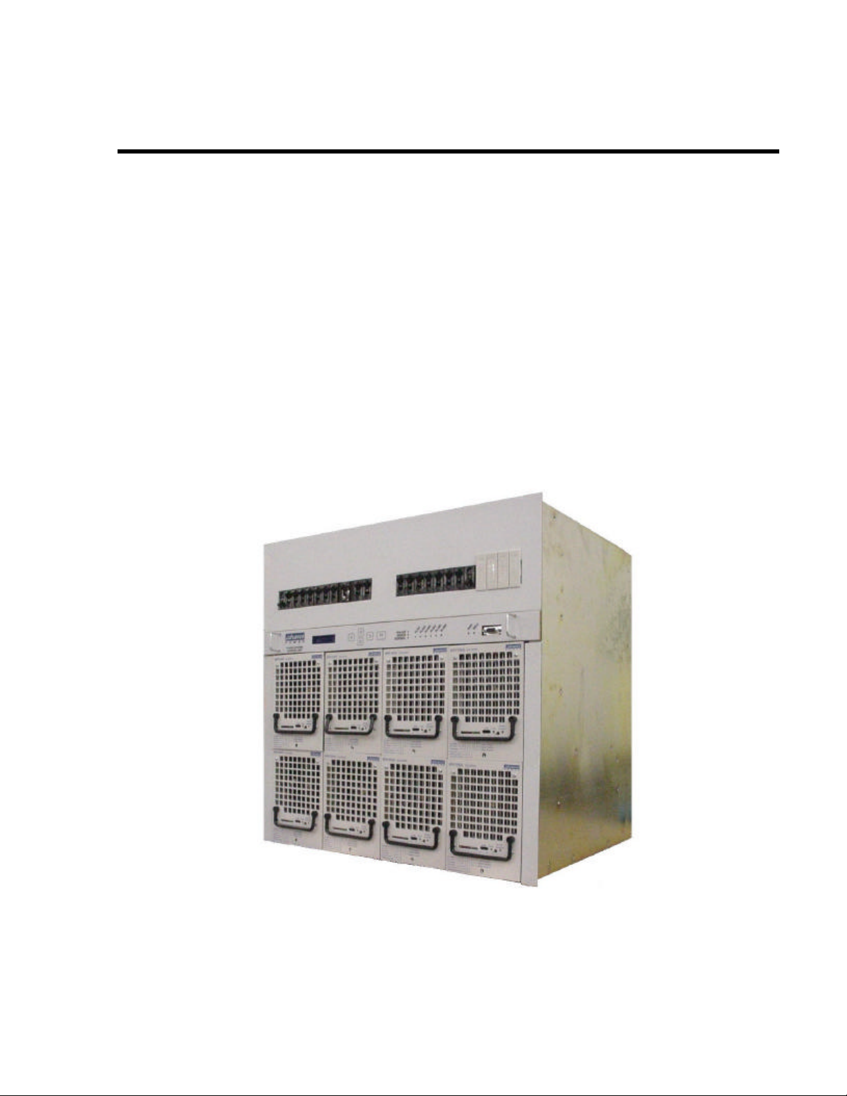
FIGURE 2.1-1 MX28B-400 –48 VDC POWER PLANT .................................................................3
FIGURE 2.1-2 MX28B BLOCK DIAGRAM ...................................................................................4
FIGURE 3.4-1 BATTERY CABLE CONNECTION LOCATIONS..............................................10
FIGURE 3.6-1 DC DISTRIBUTION (FRONT COVER REMOVED) ..........................................11
FIGURE 3.7-1. INSTALLATION OF CIRCUIT BREAKERS .....................................................14
FIGURE 3.7-2 GMT FUSE TEMPERATURE DE-RATING CHART..........................................15
FIGURE 3.8-1 STANDARD LUG FOR 1 TO 50A BREAKERS. .................................................16
FIGURE 3.8-2 ADAPTOR AND LUGS FOR 60-100 AMP BREAKERS ....................................17
FIGURE 3.8-3 INTERFACE BOARD ............................................................................................17
FIGURE 4.6-1 MENU TO P LINE...................................................................................................27
MX28B200/400 –48 VDC User’s Manual (990-9133) Page v
Page 6

Page 7
1 Safety First!
It is very important to follow all safety procedures when unpacking, installing and
operating any sort of power equipment.
1.1. Warning Symbols
CAUTION: An indication that special care is required to
prevent injury, equipment damage or misuse
WARNING: An indication of an electrical hazard that may
1.2. General Precautions:
cause serious personal injury or death, catastrophic equipment
damage or site destruction..
WARNING: The DC power plant is supplied from a nominal
220VAC, 50/60 Hz source. Keep the AC input enclosure cover
in place when the system is operational or energized
WARNING: Hazardous energy levels are present on bare
conductors in the -48VDC distribution connection area of the
plant. Accidental shorting of distribution conductors can cause
arcing and high currents that can cause serious burns or other
physical harm. It is recommended that:
• Any jewelry, rings or watches be removed while working
WARNING: Ensure that all of the DC and external AC circuit
breakers are in the OFF position prior to connecting service to
Specific CAUTION and WARNING will be placed in manual where appropriate
.
the power plant. Confirm that all voltages have been removed
including any battery sources before proceeding.
on this equipment.
• Handles of all wrenches, screwdrivers, cutters and pliers
are insulated.
• Shafts of screwdrivers are wrapped in electrical tape or
otherwise insulated
MX28B200/400 –48 VDC User’s Manual (990-9133) Page 1
Page 8

Page 9
2 Introduction
2.1. General Information
DC Power Plants from APC have unique features that make them easy to install,
maintain, and upgrade. The rectifier units are modular and truly “hot -pluggable” into the
shelf assembl y without any separate AC wiring. All system settings are made from the
system control unit that provides monitoring and control functions for each component of
the system as well as alarm listings for system diagnosis and maintenance.
The APC Model MX28B is a modular stand-alone -48V DC power plant. It is configurable
in such a manner that it will support most typical applications within the specified current
ranges (either 200 or 400 amperes) without special application engineering or assistance.
Distribution is included for up to 24 plug-in circuit breakers. These circuit breakers can
be 1 to 100 amps, with 60-100 amp breakers requiring two positions and a circuit breaker
adapter kit. An optional low voltage disconnect (LVD) can be provided on either the
battery or the load side. A 400 amp MX28B is shown in Figure 2.1-1 MX28B-400 –48
VDC Pow er Plant. A block diagram is shown in Figure 2.1–1.
Figure 2.1-1 MX28B-400 –48 VDC Pow er Plant
MX28B200/400 –48 VDC User’s Manual (990-9133) Page 3
Page 10
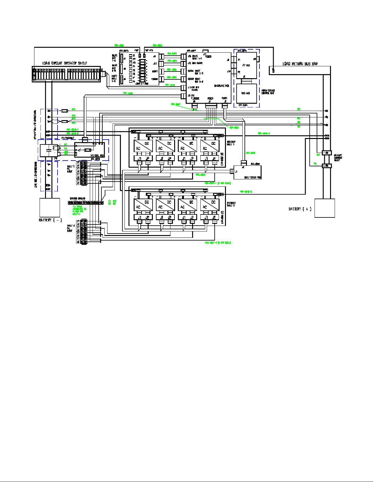
Figure 2.1-2 MX28B BLOCK DIAGRAM
Page 4 MX28B200/400 –48 VDC User’s Manual (990-9133)
Page 11

2.2. How to Use This Manual
Each section of this manual can be read in any order and should provide a complete
explanation of the subject described by the title. However, the sequence of the sections
is designed to provide a typical step-by-step process for successful use of the equipment.
Safety First! Safety symbol description and general precautions.
Introduction Brief system preview and explanation of manual
usage.
Installation How to unpack, install and commission the
equipment for initial use.
Operation Specifics of controls settings and indicators used to
operate the unit.
Remote
Monitoring
Specifications Power plant and rectifier specifications.
APC Worldwide
Customer Support
Warranty Equipment warranty terms and conditions.
Special remote monitoring and control features
described with references to information on
auxiliary equipment.
How to contact APC for customer support.
MX28B200/400 –48 VDC User’s Manual (990-9133) Page 5
Page 12

Page 13
3 Installation
3.1. Unpacking Equipment
Remove equipment from packing material and inspect for shipping damage or missing
items. It is important to report damage or material shortages to the shipping carrier while
a representative is on site.
If concealed damage or material shortages are found at a later time, contact the shipper
to make arrangements for inspection and claim filing. Refer to Section 7 in the event it is
necessary to return equipment to APC.
CAUTION: Appropriate lifting techniques and safety
equipment should be used to remove equipment from packing.
PLEASE RECYCLE: The shipping materials can be recycled.
Please save them for later use or dispose accordingly.
3.2. Mechanical Installation
Room / Location
NOTE: The APC Model MX28B DC power plant is to be installed in a room,
vault, or similar enclosure that is accessible only to qualified persons in
accordance with the NEC or the authority having jurisdiction.
Prior to installation, drawings, floor loading requirements, external alarm points, AC
service entrance, and grounding schemes should all be checked and confirmed. If
batteries are to be mounted in a room separate from the power plant, careful attention
should be paid to battery cable voltage drop effects. Environmental operating
temperatures and ventilation/cooling considerations should also be noted, not just for the
power system but also for all other equipment that may reside in the power room area.
Mounting
Both front mounting on standard 23-inch rails and optional wall mounting are available.
MX28B200/400 –48 VDC User’s Manual (990-9133) Page 7
Page 14
Ventilation
The rectifier modules for this system have fans that provide front-to-rear airflow for
internal cooling. The MX28B housing should mounted such that there is free airflow to
the front, top, and bottom of the unit. [Refer to Section 6.6 for environmental
characteristics.]
Free airflow should be ensured so that the power system can provide full power at a
given ambient temperature rating without de-rating.
3.3. AC Power Connections
WARNING: Ensure that all of the external DC and AC circuit
breakers are in the OFF position prior to connecting service to
The MX28B DC power plant requires the supply of 208/220/240/277 VAC single-phase,
50/60 Hz power through individual external 20-amp circuit breakers to the AC input
terminal block connections for each rectifier module in the system. Two rectifier modules
are required to accommodate the full AC input voltage range. The 1MRF28H54BV
rectifier is designed for the standard 208/220/240 VAC input service, while the
1MRF28H54BV50 is used for the 277 VAC input. The AC wiring, from the AC input
terminal block connections to the hot -pluggable AC input connector for each rectifier, is
factory installed.
The AC input enclosure, located at the top right rear of the MX28B housing, is provided
with two one-inch conduit entry holes and an access cover. Inside, a terminal strip(s) for
AC input power connection and a separate “Earth Ground” bar for connection of the
safety ground wire(s) are provided. The terminal block(s) is labeled as Position 1 through
Position 4 (Position 1 through Position 8 for the 400-amp unit) with each posit ion having
inputs designated “L1” and “L2/N” for connection of the two AC wires. Positions 1-4
correspond to the top rectifier shelf positions from left to right. Positions 5-8 are
applicable to the 400-amp unit only and correspond to the lower rectifier shelf positions
from left to right.
The suggested wire size is #10 AWG rated at 90°C or higher; however, the ambient
temperature and number of wires in a conduit must also be considered in accordance
with NEC requirements. It is suggested that feeds for four rectifiers (8 wires) and one
safety ground wire be run in a one-inch conduit; however, be sure to follow any local
electrical wiring codes.
If the AC input power is provided from a three-phase distribution panel, the circuit breaker
positions should be selected such that the load is balanced as much as possible.
the power plant. Confirm that all voltages have been removed
including any battery sources before proceeding.
Page 8 MX28B200/400 –48 VDC User’s Manual (990-9133)
Page 15
WARNING: The MX28B DC power plant is supplied from a
nominal 220VAC, 60 Hz source. Keep the AC input enclosure
in place when the system is operational or energized.
3.4. Battery Connections
WARNING: Hazardous energy levels are present on bare
conductors in the -48VDC distribution connection area of the
plant. Accidental shorting of distribution conductors can cause
arcing and high currents that can cause serious burns or other
physical harm. It is recommended that:
• Any jewelry, rings or watches be removed while working
Planning the Battery installation
The battery cable(s) should be sized sufficiently large to limit the voltage drop from the
MX28B DC power plant to the battery during charging per system design requirements.
The cable(s) must also carry the full load cu rrent during battery operation. If assistance
is required to determine the necessary cables for the application, contact your sales
representative or APC.
An external fuse or circuit breaker (various options are available from APC) is required in
the negative line (located at the battery end) to protect the cables from the battery to the
MX28B DC power plant. The power plant can monitor auxiliary contacts from this
breaker.
Connecting the Cables
on this equipment.
• Handles of all wrenches, screwdrivers, cutters and pliers
be insulated.
• Shafts of screwdrivers be wrapped in electrical tape or
otherwise insulated
WARNING: Make certain that the battery polarity is correct
when making connections to the Model MX28B DC power
plant. Incorrect connection could cause severe equipment
The battery cable connections are located at the top rear of the unit as shown in Figure
3.4-1. The battery positive (return bus) and battery negative (-48V bus) buses each
provide two sets of threaded 3/8”-16 holes on one-inch centers for connecting two-hole
battery cable lugs. Connect the battery cables as applicable using 3/8-16 bolts (not
provided) and tighten them with a torque wrench to 200 in -lbs (23 N-m).
MX28B200/400 –48 VDC User’s Manual (990-9133) Page 9
damage.
Page 16
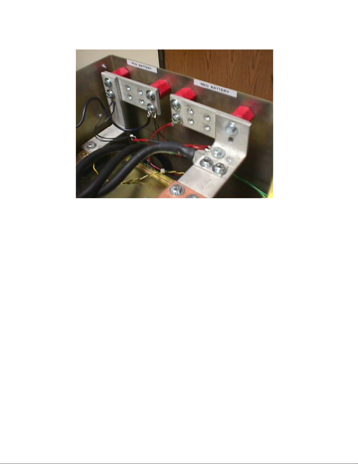
Figure 3.4-1 Battery Cable Connection Locations
Battery Temperature Probe Installation
The optional temperature probe is used to monitor the battery string temperature. To get
the most representative temperature measurement, the probe should be placed in
contact with a battery cell that is centrally located. The probe should be placed directly in
contact with the cell (not the frame surrounding the cell). Generally, the cell cover can be
used; be careful not to allow the probe body to touch the terminals. Plug the connector
end of the temperature probe into J5 of the control unit backplane card. Route the cable
as requir ed positioning the probe on the selected battery cell. Remove the adhesive
protection strip from the probe body and press the adhesive side of the probe on the
battery cell cover.
3.5. DC SYSTEM GROUNDING
The Positive Battery connection (return bus) for the power plant must be connected to the
Master Station Ground. The left end of the return bus provides a pair of threaded 3/8-16
holes on 1 inch (25.4 m) centers for connection of a two-hole lugged cable to the Master
Station Ground. Details for this connection should be provided in the site electrical
grounding plans.
Page 10 MX28B200/400 –48 VDC User’s Manual (990-9133)
Page 17
3.6. DC Power Output Over-Current Protection
DC Circuit Breakers
A standard 24-position plug-in circuit breaker tier provides -48V distribution. Various
circuit breaker sizes from 1 to 100 amps are available, with 60-100 amp breakers
requiring two positions and a circuit breaker adapter kit. The breaker tier is connected at
its center to the -48V DC bus, and each side has an ampacity of 300A. It is therefore
necessary to balance the load on the MX28B-400 plant to avoid overloading the output
bus. Also when planning the output installation, take into consideration the configuration
of the plant and the number of rectifiers installed.
Any combination of up to 24 single (1-50 Amp) or up to 12 double (60-100 Amp) breakers
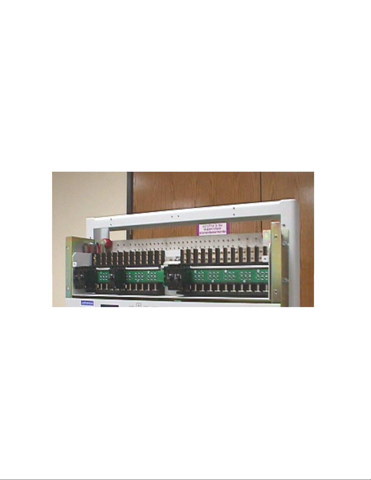
may be installed. Figure 3.6-1 shows the power plant’s DC distribution section with the
front cover removed.
Figure 3.6-1 DC Distribution (Front Cover Removed)
Available plug-in circuit breakers are shown below. These are only breakers and do not
include any hardware.
MX28B200/400 –48 VDC User’s Manual (990-9133) Page 11
Page 18
Plug-in Circuit Breakers
BREAKER
RATING
1 A FFA -0014 40 A FFA -0020
3 A FFA -0015 50 A FFA -0025
5 A FFA -0016 60 A 530-9088
10 A FFA -0017 70 A 530-9089
15 A 530-9093 80 A 530-9090
20 A FFA -0018 100 A 530-9091
30 A FFA -0019
PART NUMBER BREAKER
RATING
PART NUMBER
Plug-in circuit breakers rated at 60A or more require two mounting positions and require
a circuit breaker adapter, which is included in the circuit breaker kit. Adaptors are
available with studs for #10-32 nuts on 5/8” centers, #10-32 nuts on ¾” centers, or ¼-20
nuts on 1” centers. The circuit breaker kit includes all necessary mounting hardware.
Available plug-in circuit breakers are shown below.
BREAKER
RATING
60 A FFA -0021-1
60 A FFA -0021-2
60 A FFA -0021-3
70 A FFA -0022-1
70 A FFA -0022-2
70 A FFA -0022-3
80 A FFA -0023-1
80 A FFA -0023-2
80 A FFA -0023-3
100 A FFA -0024-1
100 A FFA -0024-2
PART NUMBER ADAPTOR SIZE
Plug-in Circuit Breaker Kits
#10 studs on 5/8” centers
#10 studs on ¾” centers
¼” studs on 1” centers
#10 studs on 5/8” centers
#10 studs on ¾” centers
¼” studs on 1” centers
#10 studs on 5/8” centers
#10 studs on ¾” centers
¼” studs on 1” centers
#10 studs on 5/8” centers
#10 studs on ¾” centers
100 A FFA -0024-3
¼” studs on 1” centers
Page 12 MX28B200/400 –48 VDC User’s Manual (990-9133)
Page 19

DC GMT Fuses
Eight GMT fused outputs are also available as an option. This option uses one of the 24
available circuit breaker positions. Connections to the GMT fuses are made at terminal
block connectors labeled “F1” through “F8” that are located on the interface card
mounted in the top left side of the unit. See Figure 2.1-1 for details. A list of GMT type
fuses available from APC is provided below.
GMT Fuses
FUSE RATING PART NUMBER
¼ A FFA-0030
½ A FFA-0031
3/4 A FFA-0032
1 A FFA-0033
1¼ A FFA-0039
1½ A FFA-0035
3 A FFA-0036
5 A FFA-0037
7½ A FFA-0029
10 A FFA-0038
Fuse cover 890-0052
MX28B200/400 –48 VDC User’s Manual (990-9133) Page 13
Page 20

3.7. Installation of Circuit Breakers and Fuses
Plug-in Circuit Breaker Installation
CAUTION During circuit breaker installation, carefully align the
breaker alarm terminals with the alarm terminal board to avoid
1) Remove the circuit breaker cover panel and the plastic cover(s) from the desired
location(s).
2) Install the circuit breaker(s) by snapping the top terminal onto the upper bus bar and
rotating the unit down until the second terminal snaps onto the breaker termination
post as shown in Figure 3.7-1 The breaker alarm terminals are designed to make
contact with the alarm terminal board as the breaker is snapped into place.
3) Reattach the circuit breaker cover panel.
NOTE: Circuit breaker alarm contacts close when the circuit breaker is
tripped but not when it is turned OFF.
breaker terminal damage.
Figure 3.7-1. Installation of Circuit Breakers
Page 14 MX28B200/400 –48 VDC User’s Manual (990-9133)
Page 21

GMT Fuse Installation
Fuse holders that accommodate GMT fuses are located on the interface card mounted in
the top left side of the unit. Insert the fuse in the holder; observing the tripped indicator is
correctly oriented. These fuse holders are only connected to -48VDC if the system has
been purchased with the GMT fuse option. This option supplies -48VDC to lugs on the
interface card through a 50 Amp circuit breaker located in circuit breaker Position 1. The
interface card provides fuse holders for eight fuses, labeled “F1” through “F8”, which can
be used for small -48V DC loads. Use the chart shown in Figure 3.7-2 to help determine
what size fuses will carry the desired current. Refer to Figure 3.8-3 for Interface board
GMT fuse locations.
AMBIENT TEMPERATURE
SIZE
FUSE
20° C 50° C 60° C
10 Amp 7 Amp 6 Amp 5 Amp
12 Amp 8 Amp 7 Amp 6 Amp
15 Amp 10 Amp 9 Amp 8 Amp
Figure 3.7-2 GMT Fuse Temperature De -rating Chart
3.8. Load Connections
Cable Size Considerations
The DC load cable(s) should be sized sufficiently large to limit the voltage drop from the
MX28B DC power plant to the loads per system design requirements. The cable(s) must
also carry the full load current during battery operation. During battery operation the
voltage will be lower and for constant power loads, therefore the current will typically be
higher. If assistance is required to determine the necessary cables for the application,
contact your sales represen tative or APC.
Circuit Breaker Connections (1 to 50 Amps)
Connections for 1 to 50 amp DC loads require standard two-hole lugs with holes for #10
screws (810-0032) on 5/8” centers and are located directly above the corresponding
circuit breaker. The load returns connect to the return bus located just above and
rearward of the breaker connection points as seen in Figure 3.8-1 The return bus
provides 24 sets of threaded #10-32 holes on 5/8” centers and four sets of threaded ¼-20
holes on ¾” centers for connection of two-hole lugs on load return wires.
MX28B200/400 –48 VDC User’s Manual (990-9133) Page 15
Page 22

Load Connections should be made as shown in Figure 3.8-1
Figure 3.8-1 Standard lug for 1 to 50A breakers.
NOTE: Load return lugs are connected to the front of the return bus to prevent
interfering with the top cover of the unit.
Circuit Breaker Connections (60-100 Amps)
Connections for 60 to 100 amp DC loads are twice as wide as the smaller breakers and
therefore require two positions and a circuit breaker adapter kit. The adaptor connects
the two output lug positions to one lug. Adaptors are available with studs for #10-32 nuts
on 5/8” centers, #10-32 nuts on ¾” centers, or ¼-20 nuts on 1” centers. The adaptor is
installed directly above the two positions the circuit breaker is mounted on using #10
screws provided in the kit. The lugs (not included with the kit) fasten on to the adaptor’s
studs using nuts and washers provided in the kit.
The load returns connect to the return bus located just above and rearward of the breaker
connection points as seen in Figure 2.1-1. The return bus provides 24 sets of threaded
#10-32 holes on 5/8” centers and four sets of threaded ¼-20 holes on ¾” centers for
connection of two-hole lugs on load return wires.
Load Connections should be made as shown in Figure 3.8-2.
Page 16 MX28B200/400 –48 VDC User’s Manual (990-9133)
Page 23

Figure 3.8-2 Adaptor and lugs for 60-100 Amp breakers
GMT Fuse Connections
GMT fuses are only connected to -48VDC if the system has been purchased with the
GMT fuse option. This option supplies -48VDC to lugs on the interface card through #6
AWG power cables controlled by a 50 Amp circuit breaker located in circuit breaker
Position 1. The 2-hole lugs on both ends of the power cables have #10 holes on 5/8”
centers. Connections to the GMT fuses are made at terminal block connectors labeled
“F1” through “F8” that are located on the interface card mounted in the top left side of the
unit. The connector is sized to accept #12 – #28 AWG wire. Each connector has two
positions, labeled “-48V” and “RTN”, for connection of the -48V DC load and load return
wires. Refer to Figure 3.8-3 for Interface board connections.
Figure 3.8-3 Interface Board
MX28B200/400 –48 VDC User’s Manual (990-9133) Page 17
Page 24

3.9. Monitoring and Relay Output Connections
Front Panel DB9 Connection
The front panel DB-9 connector is used to hook up a standard serial cable for the APC
proprietary GUI that will be introduced at a later date. Do not hook up the special RS-232
cable (APC part number 940-0024C). This cable is only to be used with the DB-9 near
the Web/SNMP card.
“Smart” Cable DB9 Connection
The DB9 connector on the top right hand side of the unit uses the special RS-232 cable
(APC part number 940-0024C) to allow local access through a Terminal Emulation
program like HyperTerminal™ or Procomm™ (**).
RJ45 Ethernet Connector
The optional management card has an RJ-45 connector to support a TCP/IP protocol
over a 10BaseT Ethernet Local Area Network (LAN).
Relay Output Connections
There are eight alarms available that provide outputs via Form “C” relay contacts. The
last two of these are preassigned as the Minor and Major relay outputs. The Major relay
is energized (NO-C contacts closed) during normal (non -alarm) operating conditions; all
the other relays energize when an alarm condition occurs. The other six outputs are
initially designated as “Relay 1” through “Relay 6” (the user may assign more meaningful
names if desired). The various system alarm conditions can be assigned to any of the
eight alarm outputs. Connectors J1 and J2 are located on the interface card mounted in
the top left side of the unit. Refer to the board layout in Figure 3.8-3 for Output Relay
connections. The relay contacts should only be used to switch resistive loads of 0.5
amperes or less at 60 volts or less. The following shows the alarm output connection
designations.
Page 18 MX28B200/400 –48 VDC User’s Manual (990-9133)
Page 25

Output Relay Connections
RELAY
OUTPUT
TERMINAL
DESIGNATION
USER ALARM NOTES
NO-NC-C
RELAY #1
RELAY #2
RELAY #3
RELAY #4
RELAY #5
RELAY #6
MINOR
MAJOR
J1
NO1-NC1-C1
NO2-NC2-C2
NO3-NC3-C3
NO4-NC4-C4
J2
NO5-NC5-C5
NO6-NC6-C6
NO7-NC7-C7
NO8-NC8-C8
________________________
________________________
________________________
________________________
________________________
________________________
________________________
________________________
3.10. External Alarm Input Connections
Four external alarm inputs with assignable priority levels are available. These alarm
inputs respond to external dry contact closures between normally open (NO) and
common (C) or contact openings between normally closed (NC) and C.
External Alarm Input Definition
External Alarm Source
(non -alarm state)
OPEN
CLOSED
Connect To Input
Alarm Terminals
NO-C
NC-C
Connector J4 is located on the interface card mounted in the top left side of the unit.
Refer to Figure 3.8-3 for Interface board connections. Systems are shipped with jumper
wires connecting each NC and corresponding C contact. A jumper wire should be
removed only if the corresponding NC-C contacts are going to be used.
External Alarm Input Connections
EXTERNAL
ALARM
INPUT
#1
#2
#3
#4
J4 TERMINAL
DESIGNATION
(NO-NC-C)
NO1-NC1-C1
NO2-NC2-C2
NO3-NC3-C3
NO4-NC4-C4
USER ALARM NOTES
___________________________
___________________________
___________________________
___________________________
MX28B200/400 –48 VDC User’s Manual (990-9133) Page 19
Page 26

3.11. Rectifier Module Installation
WARNING: Rectifier DC output circuits would be damaged if
battery were installed incorrectly. Before rectifier installation,
The rectifier modules are shipped in separate containers. Follow the procedure below to
install a rectifier module.
1) Remove the rectifier from its shipping container.
2) Remove any rectifier retaining screws from the shelf position where the rectifier is
to be installed.
3) Slide the rectifier module into the shelf between the guides until it is fully seated.
4) Fasten the rectifier in place with the rectifier retaining screw (included in literature
kit with product manual).
Since all adjustments are made from the system control unit, no rectifier adjustments are
necessary.
ensure proper battery polarity and that the battery is isolated
from the rest of the system
NOTE: All “FLOAT” – “BOOST/EQUALISE” switches (one is located on the front
of each rectifier in the system) must be set to “FLOAT” to allow the MX28B to
control the output voltage properly.
CAUTION: Rectifier fan inlet filters are available for dusty or
hostile environments. Failure to periodically check and clean
filters can lead to rectifier shutdown due to over temperature
and produce power plant failure.
3.12. Initial Power-Up and Checkout
Before initiating power-up and checkout, ensure that the following conditions exist:
1) Make sure that the external circuit breaker protecting the cables from the battery to
the power plant is turned OFF (the battery cables should be connected to the
power plant, but the battery should not be connected).
2) Make sure that all load circuit breakers are turned OFF (including the one feeding
the GMT fuses if the unit has the GMT fuse option).
Page 20 MX28B200/400 –48 VDC User’s Manual (990-9133)
Page 27

3) Verify that all rectifiers hav e been installed.
4) Apply AC Power. Turn on the circuit breakers that supply ac power to the rectifiers
in the MX28B DC power plant. The main screen should appear on the control unit
display (see Figure 4.6-1). The display on the control unit is a 2-lines by 16characters display. The cursor cycles below the characters of the active selection
on the display. Information shown in the second line of Figure 4.6-1 that exten ds
beyond 16 characters (to the right of the “S” in “ALARMS”) can viewed on the
control unit display by using the scrolling controls (refer to Section 4.6 for
operation of the control unit).
NOTE: When AC power is initially applied, there is a 60-second period during
which no alarms are reported.
WARNING: The DC power plant is supplied from a nominal
220VAC, 50/60 Hz source. Keep the AC input enclosure cover
.
in place when the system is operational or energized
3.13. System Parameters Verification/Adjustment
The MX28B system control unit is delivered with pre-programmed parameter default
settings. A complete listing and description of all system configuration parameters as
well as displayable system status and information is provided in Section 4.6. Read
Section 4.1 to gain an understanding of and how to use the operational features
provided by the MX28B DC power plant. As a minimum, the following parameters should
be verified and adjusted, if required, before connecting batteries or loads to the power
plant:
1) Battery Float Voltage - default = -54.00V DC (Check the manufacturer’s
recommendation for the batteries being used in the system.)
2) Battery Maximum Recharge Rate - default = 12A. (Bellcore specifications
recommend a maximum charging rate of capacity (in Ampere-hours) divided by 20
hours; check the manufacturer’s recommendation.)
3) System Voltage - measurement ≅ -54.00V DC (This is a measurement by the
system of the DC output bus voltage.)
4) LVD Option - default = “Enable” (If the MX28B does not have an LVD installed,
this should be changed to “Disable”.)
5) Rectifier Information - Check the rectifier information displays to verify that all
rectifiers installed can be viewed on the control unit display and that no rectifier
alarms are active.
Section 4.6 provides location information for these parameters and how to make
changes if required.
MX28B200/400 –48 VDC User’s Manual (990-9133) Page 21
Page 28

3.14. Full System Power Up
To complete a full system power up, perform the following steps:
1) Turn OFF all the circuit breakers that supply ac power to the rectifiers in the MX28B
DC power plant.
Turn on the external circuit breaker from the battery to the power plant.
Turn on all the circuit breakers that supply AC power to the rectifiers in the MX28B DC
power plant.
Load circuit protection may now be enabled as required.
Page 22 MX28B200/400 –48 VDC User’s Manual (990-9133)
Page 29

4 Operation
4.1. Technical Description
The MX28B-200/400 Power System is designed to supply safe –54 VDC primary power
through the use of up to eight rectifier modules. In conjunction with an external battery
string, it will supply backup power as well. The Power System Control Unit (PSCU) will
monitor all MX28B functions and provides battery management including controlled
battery recharge with temperature compensation and low voltage disconnect. Integrated
DC output distribution supports loads ranging from ¼ Amp all the way to 100 Amp is
available. Battery recharging, temperature compensation and low voltage disconnect are
included. The controller can monitor up to 4 discrete external events with dry contact
inputs.
4.2. Rectifier Management
AC Input Power
The basic component of the power system is the rectifier module, which rectifies utility
AC into nominal 48 Volts DC. Each rectifier module requires 208/220/240V AC
(MRF28H54BV), or 277V ac (MRF28H54BV50) single-phase, 50/60 Hz. A breaker
installed in a remote panel should individually protect each rectifier circuit.
DC Output Power
The DC outputs of all the rectifiers in the system are connected to a common bus that is
rated to carry the current of the entire system. The rectifier modules will equally share
the entire load, independent of the PSCU. The rectifiers will continue to provide DC
power if the PSCU is removed or fails.
Rectifier alarms reporting
The rectifier has numerous sensors inside the unit that monitor fan fail, high temperature,
high/low voltage, etc. These rectifier sensors trigger outputs that are monitored by the
PSCU. In addition rectifier current is measured inside each rectifier. The PSCU can
trigger output relays in the event of a rectifier alarm. Refer to Section 4.6 for PSCU
control functions.
MX28B200/400 –48 VDC User’s Manual (990-9133) Page 23
Page 30

4.3. System Management
System Output Capacity
The power plant has two basic configurations:
The MX28B-200 supplies a maximum of 200 amps or 150 amps with N+1 redundancy.
The housing for this configuration provides space for one rectifier shelf that can hold up
to four rectifiers, a control unit, and one tier of up to 24 distribution circuit breakers.
The MX28B-400 supplies a maximum of 400 amps or 350 amps with N+1 redundancy.
The housing for this configuration provides space for two rectifier shelves that can hold
up to four rectifiers each, a control unit, and one tier of up to 24 distribution circuit
breakers. The differences between the 200 and 400 amp units are the exterior housing,
50-conductor ribbon cable and an additional rectifier shelf; all other parts are the same for
both configurations.
System Voltage Control
The PSCU monitors and adjusts the system voltage. It uses a voltage trim input to the
rectifier to precisely control the DC output voltage. In the event of PSCU removal or
failure, the shelf rectifier controller card will control the voltage at a programmed default
level. In the event of shelf rectifier controller card failure, the individual rectifiers will
default to the analog voltage level preset with the front panel “float’ adjustment pots.
System Current
The PSCU monitors individual rectifier currents and displays total system current as a
sum of rectifier currents. Load current can be found by adding battery current to system
current. Battery Current is positive when the battery is discharging.
Sys Current + Batt cu rrent = Load Current
For example, if the battery is charging the Batt Current reading could be (–) 40 A, Sys
Current reading could be 120 A. Load Current would be:
Sys Current + Batt current = Load Current
120A + (-) 40 A = 80 Amps.
If the battery is discharging the Batt Current reading would be 40 A, Sys Current would
reading would be 40 A. Load voltage would be:
Sys Current + Batt current = Load Current
40A + 40 A = 80 Amps.
Page 24 MX28B200/400 –48 VDC User’s Manual (990-9133)
Page 31

System Status and Alarm Reporting
The PSCU will monitor system voltage using a high accuracy digital voltmeter attached to
the system bus. The PSCU will monitor system temperature using a temperature IC
mounted in the PSCU. The PSCU will monitor system current by summing the current
reported by individual rectifiers. The PSCU will report a number of system alarms
including system high/low voltage and high/low temperature. Refer to Section 4.6 for
PSCU control functions.
4.4. DC Distribution
Distribution is included for up to 24 plug-in circuit breakers. These circuit breakers can
be 1 to 100 amps, with 60-100 amp breakers requiring two positions and a circuit breaker
adapter kit. When a circuit breaker trips, a normally open switch closes and a CB alarm
is reported by the PSCU. To disconnect a load attached to a circuit breaker, move the
lever to the down “OFF” position.
NOTE: Circuit breaker alarm contacts close when the circuit breaker is
tripped but not when it is turned OFF.
Eight GMT fused outputs are also available as an option. This option uses one of the 24
available circuit breaker positions. When a GMT fuse trips, an alarm spring is revealed
that visually indicates the fuse is blown. The alarm spring also makes contact with a third
contact on the fuse holder, which connects the –48 VDC bus voltage to the GMT fuse
alarm input in the PSCU. Upon measuring voltage on this alarm circuit, the PSCU will
report a GMT fuse alarm. To disconnect a load attached to a GMT fuse, pull the fuse out
of the fuse socket.
NOTE: GMT fuse alarm cont acts complete the alarm circuit when the fuse
is tripped but not when the fuse is removed.
4.5. Battery Management
Battery Charging and Protection
Battery charging and protection are integrated into the MX28B DC power system to
support the primary function of providing power to the load. Accurate measurement of
battery parameters like voltage, current and temperature are used to maintain and protect
the batteries attached to the power plant.
Charging the battery at the correct rate reduces battery heatin g, increases the charge
returned to the battery and prevents excess hydrogen generation or, in the case of VRLA
MX28B200/400 –48 VDC User’s Manual (990-9133) Page 25
Page 32

batteries, possible thermal runaway. Battery Maximum Recharge Current is set to the
appropriate rate, which is usually based on the size of the battery plant in Ampere-hours.
A typical recharge current setting is battery capacity (abbreviated as “C”) divided by
number of charging hours. As an example, a “C/10” rate will basically return the battery
to full charge in 10 hours. A C/8 rate is probably the highest current, which should be
considered for charging under normal circumstances.
Battery Temperature Compensation
The Battery Float Voltage is set to the value recommended by the battery manufacturer
in order to maintain correct battery charge at 25ºC. As temperature rises,
electrochemical activity in a battery increases. Similarly, as temperature falls,
electrochemical activity in a battery decreases. As temperature rises charging voltage
should be reduced to prevent overcharge and increased as temperature falls to prevent
undercharge. The DC power system uses Battery Temperature compensation to change
output voltage to compensate for temperature changes. This temperature compensation
function is programmed into the PSCU using the compensation parameters settings.
Default settings can be changed to values recommended by the particular battery
manufacturer.
Battery/Load Low Voltage Disconnect
In order to prevent damage to the battery due to deep discharge, the DC power system
has hardware and software support for a battery or load Low Voltage Disconnect (LVD).
A battery LVD has the loads permanently attached to the rectifiers and the battery is
disconnected from the system. A load LVD has the battery permanently attached to the
rectifiers and the loads are disconnected from the system.
When the battery voltage reaches the threshold set by the LVD 1 Trip Voltage setting
during discharge, the DC power system will activate the LVD contactor to disconnect the
battery or load from the system. The LVD will remain open until AC power is restored to
the system and the bus voltage reaches the level defined by the LVD 1 Reset Voltage
variable.
NOTE: The LVD is normally energized and must be commanded to open. This
assures that the LVD will remain closed even if the controller fails or is removed.
4.6. Controls and Indicators
Front Panel User Interface
The MX28B control unit provides a user interface designed with a hierarchical menu that
can be viewed on the 32-character (2 X 16) display by “navigating” with the “ï” (left), “ð”
Page 26 MX28B200/400 –48 VDC User’s Manual (990-9133)
Page 33

(right), “ñ” (up), and “ò” (down) arrow keys located on the front panel. The selected item
on the display is identified by the cursor cycling beneath its characters.
The “M” (modify) key and the arrow keys are used to set parameters and text to
customize the system operation for a specific application. Items that can be modified
have "m+" in the upper right corner of the display. If a security level higher than the one
presently set is required to modify the parameter, "s+" is displayed instead of “m+”.
Status, alarms, and information screens have "+" in the upper right corner of the display
(or “#” in the case of rectifier information screens) and cannot be modified. When AC
power is initially applied, there is a 60-second period during which no alarms are
reported.
Pressing the "M" key on the front panel will change the "m+" to "M+", indicating that the
parameter can now be changed using the arrow keys. Some parameters can be
changed to other predefined sel ections by pressing the up or down arrow keys to display
an alternative selection. These parameters can be recognized after the “M” key is
pressed by the cursor cycling beneath the characters of the selection. For other
parameters, such as text and most numeric values, after the “M” key is pressed the
cursor will be displayed under an individual character. The right or left arrow key is used
to position the cursor below the character to be changed and the up or down arrow key is
used to "spin" the digit or letter to the desired value. When the desired changes have
been made to an individual parameter screen, the “M” key is pressed again; the “M+”
changes back to “m+” and the new entry is stored in memory.
If the user plans to make any changes to system parameters, the first item that should be
verified or entered is the appropriate password for the security level required for the
parameters to be modified. Security level 2 (enter 2222 on the “PIN” screen) enables
modification of all variable system parameters. Security level 1 (enter 1111 on the “PIN”
screen) permits modification of some parameters. No security is required for viewing
status items and parameter settings. The security level password is entered through the
“PIN” screen. If no front pan el keys are pressed for 60 minutes, the active security level
password reverts to level 0 and “¦APC¦” begins to move about the display. Pressing
any key returns the display to normal and the password must be re-entered if system
parameters require changes.
Eleven LEDs are provided on the front panel of the control unit to indicate system status.
Three LEDs grouped together vertically provide overall system status; they are “MAJOR”,
“MINOR”, and “NORMAL”, indicating the presence of a major alarm, a minor alarm, or
normal operation. The other eight LEDs correspond to the active state of each of the
alarm output relays and are labeled “ALM1”···“ALM6”, “MIN”, and “MAJ”.
MX28B +
STATUS ALARMS SYSTEM MODULES BATT PIN OEM
Figure 4.6-1 Menu Top Line
.
MX28B200/400 –48 VDC User’s Manual (990-9133) Page 27
Page 34

Parameter Locations, Descriptions, and Default Values
The location, description, and factory programmed default value for each of the
MX28B system parameters is found in the table below. The table also shows all of
the status and information screens with typical displays. The location of a parameter
screen is shown in brackets, for example: [SYSTEM/IN-RLY/RLY-MAP]. To find the
parameters that can be accessed in this category, starting from the main menu
screen, do the following:
1) Use the right or left arrow keys to position the cycling cursor bel ow “SYSTEM”.
2) Press the down arrow key once.
3) Use the right arrow key to position the cycling cursor below “IN-RLY”.
4) Press the down arrow key once; the cursor will be cycling below “RLY-MAP”.
5) Press the down arrow key (repeatedly if necessary) until the desired parameter
screen is displayed (there are eight parameter screens in this category).
After making any desired changes, return to the main menu press the up arrow key
repeatedly.
If a parameter requires a level 1 or level 2 security access to permit changes to it, the
security level will be found in braces, i.e. Security Level {2}, in the “PARAMETER” column
of the table.
PARAMETER NAME/
[MENU LOCATION]
Address 1
Security Level {1}
[SYSTEM/SETUP]
Address 2
Security Level {1}
[SYSTEM/SETUP]
Address 3
Security Level {1}
[SYSTEM/SETUP]
Alarms Item 1
{Status Only}
[ALARMS]
•
•
•
Alarms Item 16
[ALARMS]
Battery Current
{Status Only}
[STATUS]
Parameter Locations, Descriptions, and Default Values
DESCRIPTION DISPLAY SCREENS /
DEFAULT SETTINGS
Power plant address or identification first line.
Power plant address or identification second line.
Power plant address or identification third line.
Display of up to 16 active alarms (a
typical alarm screen is shown).
•
•
•
Display of up to 16 active alarms (a
typical alarm screen is shown).
Address 1 m+
APC DCNS, Inc.
Address 2 m+
11035 Switzer Av
Address 3 m+
Dallas, TX.
Alarm Item 1 +
Batt LV Alm Onm
•
•
•
Alarm Item 16 +
No Alarms
Battery current measured by the system
controller at the battery current shunt.
Batt Current +
-15.0 A
Page 28 MX28B200/400 –48 VDC User’s Manual (990-9133)
Page 35

PARAMETER NAME/
[MENU LOCATION]
Battery Discharge Alarm
Security Level {1}
[BATT/SET-ALM]
Battery Discharge Threshold
Security Level {1}
[BATT/SET-ALM]
Battery Float Voltage
Security Level {1}
[BATT/PARAM]
Battery High Temperature
Alarm
Security Level {1}
[BATT/SET-ALM]
Battery High Temperature
Threshold
Security Level {1}
[BATT/SET-ALM]
Battery High Voltage Alarm
Security Level {1}
[BATT/SET-ALM]
Battery High Voltage Threshold
Security Level {1}
[BATT/SET-ALM]
Battery Low Temperature
Alarm
Security Level {1}
[BATT/SET-ALM]
Battery Low Temperature
Threshold Security Level {1}
[BATT/SET-ALM]
Battery Low Voltage Alarm
Security Level {1}
[BATT/SET-ALM]
Battery Low Voltage Threshold
Security Level {1}
[BATT/SET-ALM]
Battery Maximum Recharge
Current
Security Level {1}
[BATT/PARAM]
Battery Temperature
{Status Only}
[STATUS]
DESCRIPTION DISPLAY SCREENS /
The output relay energized if the battery
discharge current exceeds the
programmed battery discharge threshold.
An alarm is generated if the battery
discharge current exceeds this value.
One of three parameters that control the
DC output voltage. Set the Float Voltage
at 25°C battery temperature per the
battery manufacturers recommendations.
The output relay energized if the battery
temperature exceeds the Battery High
Temperature threshold.
Battery Temperature is temperature
measured at the battery probe. An alarm
is generated if the battery temperature
exceeds this value.
The output relay energized if the DC
output voltage rises above the battery
high voltage threshold.
An alarm will be reported if temperature
is lower than the temperature entered.
An alarm is generated if the DC output
voltage rises above this value.
The output relay energized if the Battery
Temperature drops below the battery
Low Temperature threshold.
Battery Temperature is temperature
measured at the battery probe. An alarm
is generated if the battery temperature
drops below this value.
The output relay energized if the DC
output voltage drops below the battery
low voltage threshold.
An alarm is generated if the DC output
voltage drops below this value.
One of three parameters that control the
DC output voltage. If Battery Current
surpasses the Maximum Battery
Recharge Current, the DC output voltage
will be reduced (the system limits the
charging current to this programmable
value).
Battery temperature measured by the
system controller at the optional battery
temperature sensor probe.
DEFAULT SETTINGS
Batt Disc Alm m+
Minor
Batt Disc Thr m+
10 A
Batt Float m+
-54.00 V
Batt HT Alm m+
Minor
Batt HT Thr m+
70.0 C
Batt HV Alm m+
Minor
Batt HV Thr m+
-58.00 V
Batt LT Alm m+
Minor
Batt LT Thr m+
0.0 C
Batt LV Alm m+
Minor
Batt LV Thr m+
-44.00 V
Batt Max Rechm+
12 A
Batt Temp +
25.2 C
MX28B200/400 –48 VDC User’s Manual (990-9133) Page 29
Page 36

PARAMETER NAME/
[MENU LOCATION]
Circuit Breaker 1 Alias
Security Level {1}
[MODULES/CIRBKR/ALIAS]
•
•
•
Circuit Breaker 24 Alias
Security Level {1}
[MODULES/CIRBKR/ALIAS]
Circuit Breaker 1 Tripped
Security Level {1}
[MODULES/CIRBKR/SETALM]
•
•
•
Circuit Breaker 24 Tripped
Security Level {1}
[MODULES/CIRBKR/SETALM]
Compensation High Knee
Security Level {1}
[BATT/COMP]
Compensation Low Knee
Security Level {1}
[BATT/COMP]
Compensation Method
Security Level {1}
[BATT/COMP]
Compensation Temperature
Coefficient
Security Level {1}
[BATT/COMP]
Control Unit Revision
{Status Only}
[SYSTEM/SETUP]
Date
Security Level {1}
[SYSTEM/DATE]
Display Type
{Status Only}
[SYSTEM/SETUP]
Fahrenheit Scale
Security Level {1}
[SYSTEM/SETUP]
DESCRIPTION DISPLAY SCREENS /
An alternate name (alias) that can be
assigned to a circuit breaker if desired.
•
•
•
An alternate name (alias) that can be
assigned to a circuit breaker if desired.
An alarm that indicates Circuit Breaker 1
is tripped.
•
•
•
An alarm that indicates Circuit Breaker
24 is tripped.
The temperature compensation high
knee is the point above which there is no
additional battery voltage compensation
for further increases in temperature.
The temperature compensation low knee
is the point below which there is no
additional battery voltage compensation
for further decreases in temperature.
One of three parameters that control the
DC output voltage. Activate “ON” or deactivate “OFF” battery temperature
compensation.
Temperature compensation coefficient
between low knee and high knee in
mV/cell/°C. (Compensation equals zero
at 25°C.)
Hardware revision level of the control
unit. This parameter cannot be changed.
Internal system calendar date. Used as
a date stamp in the event log.
Type number for the control unit display.
This parameter cannot be changed.
Enables selection of Fahrenheit or
Celsius temperature scale (Fahrenheit
“OFF” displays readings in °C).
DEFAULT SETTINGS
Cir Bkr 1 m+
-48V
•
•
•
Cir Bkr 24 m+
-48V
Cir Bkr 1 Alm m+
Major
•
•
•
Cir Bkr 24 Almm+
Major
Comp Hknee m+
40.0 C
Comp Lknee m+
0.0 C
Comp Method m+
OFF
Comp TC m+
- 3.00mV
Cntrl Rev +
000002
Date m+
DEC 16 1999
Display Type +
000255
Fahrenheit m+
OFF
Page 30 MX28B200/400 –48 VDC User’s Manual (990-9133)
Page 37

PARAMETER NAME/
[MENU LOCATION]
Firmware Version
{Status Only}
[SYSTEM/SETUP]
GMT 1 Alias
Security Level {1}
[MODULES/GMT/ALIAS]
•
•
•
GMT 8 Alias
Security Level {1}
[MODULES/GMT/ALIAS]
GMT 1 Blown
Security Level {1}
[MODULES/GMT/SET-ALM]
•
•
•
GMT 8 Blown
Security Level {1}
[MODULES/GMT/SET-ALM]
Hardware Battery Current
Alarm
Security Level {2}
[SYSTEM/SET-ALM]
Hardware Battery Temperature
Alarm
Security Level {2}
[SYSTEM/SET-ALM]
Hardware LVD Alarm
Security Level {2}
[SYSTEM/SET-ALM]
Hardware System Temperature
Alarm
Security Level {2}
[SYSTEM/SET-ALM]
Hardware System Voltage
Alarm
Security Level {2}
[SYSTEM/SET-ALM]
DESCRIPTION DISPLAY SCREENS /
Version number of the control unit
firmware.
NOTE: Actual firmware version
number displayed is the current
version as of the date of manufacture.
This parameter cannot be changed.
An alternate name (alias) that can be
assigned to a GMT Fuse 1 if desired.
•
•
•
An alternate name (alias) that can be
assigned to a GMT Fuse 8 if desired.
The Output Relay that is energized when
GMT Fuse 1 is blown.
•
•
•
The Output Relay that is energized when
GMT Fuse 8 is blown.
The output relay energized if there is a
hardware failure in the battery current
monitoring function.
The output relay energized if there is a
hardware failure in the battery
temperature monitoring function.
The output relay energized if there is a
conflict between the commanded and
sensed positions of the LVD contactor.
Generally the contactor is open when it
should be closed.
The output relay energized if there is a
hardware failure in the system
temperature monitoring function.
The output relay energized if there is a
hardware failure in the system voltage
monitoring function.
DEFAULT SETTINGS
FW Version +
000189
GMT 1 m+
-48V
•
•
•
GMT 8 m+
-48V
GMT 1 Alm m+
Major
•
•
•
GMT 8 Alm m+
Major
Hw Batt C Almm+
Minor
Hw Batt T Almm+
Minor
Hw LVD Alm m+
Minor
Hw Sys T Alm m+
Minor
Hw Sys V Alm m+
Minor
MX28B200/400 –48 VDC User’s Manual (990-9133) Page 31
Page 38

PARAMETER NAME/
[MENU LOCATION]
Input Relay 1
Security Level {1}
[SYSTEM/IN-RLY/RLY-MAP]
•
•
•
Input Relay 4
Security Level {1}
[SYSTEM/IN-RLY/RLY-MAP]
Input Relay 1 Alias
Security Level {1}
[SYSTEM/IN-RLY/ALIAS]
•
•
•
Input Relay 4 Alias
Security Level {1}
[SYSTEM/IN-RLY/ALIAS]
Lamp Test
Security Level {1}
[SYSTEM/DIAG]
LVD 1 or 2 Option
Security Level {1}
[MODULES/LVD/SET-ALM]
LVD 1 or 2 Reset
Security Level {1}
[MODULES/LVD/PARAM]
LVD 1 or 2 Trip
Security Level {1}
[MODULES/LVD/PARAM]
LVD Alarm
Security Level {1}
[MODULES/LVD/SET-ALM]
Model Programming
Security Level {2}
[SYSTEM/SETUP]
OEM R Gain
Security Level {2}
[OEM]
OEM R Offset
Security Level {2}
[OEM]
OEM S Gain
Security Level {2}
[OEM]
DESCRIPTION DISPLAY SCREENS /
The Output Relay that is energized when
an external contact closure or opening at
the Input Relay 1 connection changes
state.
•
•
•
The Output Relay that is energized when
an external contact closure or opening at
the Input Relay 4 connection changes
state.
An alternate name (alias) can be
assigned to Input Relay 1 if desired.
•
•
•
An alternate name (alias) can be
assigned to Input Relay 1 if desired
Setting Lamp Test to “ON” will turn on
the “MAJOR”, “MINOR”, “NORMAL”,
“MAJ”, and “MIN” LEDs on the control
unit front panel.
Must be set to “Enable” if the unit has an
LVD. If the unit has an LVD, but it is
disabled, the controller will not
disconnect the LVD.
LVD Reset (reconnect) threshold voltage.
LVD Trip (disconnect) threshold voltage.
The output relay that is energized when
the controller opens the LVD. If unit has
a battery LVD, no power will be available
to turn on any Output Relays.
Model type number for the MX28B DC
power plant
NOTE: Changing the model number
causes the system to reinitialize.
Voltage gain adjustment for factory
calibration of system voltage
readings/settings.
Voltage offset adjustment for factory
calibration of system voltage
readings/settings.
Current gain adjustment for factory
calibration of battery current
readings/settings.
DEFAULT SETTINGS
In-Rly 1 Alm m+
Ignore
•
•
•
In-Rly 4 Alm m+
Ignore
In-Rly 1 m+
Input Relay 1
•
•
•
In-Rly 4 m+
Input Relay 4
Lamp Test m+
OFF
LVD Option m+
Enable
LVD Reset m+
-48.00 V
LVD Trip m+
-42.00 V
LVD Open Alm m+
Minor
Model m+
MX28B-200/400
OEM R Gain m+
1.000 V
OEM R Offset m+
0.000 V
OEM S Gain m+
1.000 A
Page 32 MX28B200/400 –48 VDC User’s Manual (990-9133)
Page 39

PARAMETER NAME/
Relay Major
Relay Minor
[MENU LOCATION]
OEM S Offset
Security Level {2}
[OEM]
Output Relay 1 Alarm
Security Level {1}
[SYSTEM/OUT-RLY/RLYMAP]
•
•
•
Output Relay 6 Alarm
Security Level {1}
[SYSTEM/OUT-RLY/RLYMAP]
Output Relay 1 Alias
Security Level {1}
[SYSTEM/OUT-RLY/ALIAS]
•
•
•
Output Relay 6 Alias {1}
[SYSTEM/OUT-RLY/ALIAS]
Output Relay 1 Delay
Security Level {1}
[SYSTEM/OUT-RLY/RLYMAP]
•
•
•
Output Relay 6 Delay
Security Level {1}
[SYSTEM/OUT-RLY/RLYMAP]
Output Relay Major Alias
Security Level {1}
[SYSTEM/OUT-RLY/ALIAS]
Output Relay Minor Alias
Security Level {1}
[SYSTEM/OUT-RLY/ALIAS]
PIN 1 change
Security Level {2}
[SYSTEM/SETUP]
PIN 2 Change
Security Level {2}
[SYSTEM/SETUP]
DESCRIPTION DISPLAY SCREENS /
Current offset adjustment for factory
calibration of battery current
readings/settings.
Output Relay 1 Alarm can be “mapped”
to activate other output relays (“Ignore”
activates no additional relays).
•
•
•
Output Relay 6 Alarm can be “mapped”
to activate other output relays (“Ignore”
activates no additional relays).
An alternate name (alias) can be
assigned to Output Relay 1 if desired.
•
•
•
An alternate name (alias) can be
assigned to Output Relay 6 if desired.
Delay between sensing of the alarm
condition and activation of Output Relay
1. An alarm condition must exist for
longer than the delay to be activated.
•
•
Delay between sensing of the alarm
condition and activation of Output Relay
6. An alarm condition must exist for
longer than the delay to be activated.
An alternate name (alias) can be
assigned to the major Relay if desired.
An alternate name (alias) can be
assigned to the Minor Relay if desired.
Permanently change password (PIN) that
permits security Level 1 parameter
changes - limited access.
Permanently change password (PIN) that
permits security Level 2 parameter
changes - unlimited access.
DEFAULT SETTINGS
OEM S Offset m+
0.0 A
Out-Rly 1 Alm m+
Ignore
•
•
•
Out-Rly 6 Alm m+
Ignore
Out-Rly 1 m+
Relay 1
•
•
•
Out-Rly 6 m+
Relay 6
Out-Rly 1 Dly m+
0 sec
•
•
•
Out-Rly 6 Dly m+
0 sec
m+
Major
m+
Minor
PIN m+
1111
PIN 2 m+
2222
MX28B200/400 –48 VDC User’s Manual (990-9133) Page 33
Page 40

PARAMETER NAME/
[MENU LOCATION]
PIN Entry
Security Level {0}
[PIN]
Rectifier Communications Fail
Timeout
Security Level {1}
[MODULES/RECT/PARAM]
Rectifier Configuration Alarm
Security Level {1}
[SYSTEM/SET-ALM]
Rectifier Current Limit Alarm
Security Level {1}
[MODULES/RECT/SET-ALM]
Rectifier Current Limit Alarm
Status
{Status Only}
[MODULES/RECT/INFO]
Rectifier Current Output Status
{Status Only}
[MODULES/RECT/INFO]
Rectifier Description
{Status Only}
[MODULES/RECT/INFO]
Rectifier Fail 1-of-N Alarm
Security Level {1}
[SYSTEM/SET-ALM]
Rectifier Fail 2-of-N Alarm
Security Level {1}
[SYSTEM/SET-ALM]
Rectifier Fail Safe Voltage
Security Level {1}
[MODULES/RECT/PARAM]
Rectifier Fan Fail Alarm
Security Level {1}
[MODULES/RECT/SET-ALM]
DESCRIPTION DISPLAY SCREENS /
Screen for entry of the active password
(PIN). Before any changes can be
made, the correct pin for the desires
security level must be entered. Level 0 –
full read access. Level 1 –full read and
limited write access. Level 2 – full read
and write access.
The maximum rectifier communications
response time allowed before a
communications failure is declared.
The output relay energized if the rectifier
configuration differs from its stored
configuration. This occurs if a rectifier is
added after configuration.
The output relay that is energized or
special rectifier alarm group n of N that
occurs when a rectifier has been forced
into the current limited mode.
The status will be “ON” if the rectifier has
been forced into its current limited mode.
NOTE: This information can be
viewed for each rectifier installed by
using the horizontal arrow keys.
A display of the DC output current for the
individual rectifier. NOTE: This
information can be viewed for each
rectifier installed by using the
horizontal arrow keys.
Displays the model number of the
installed rectifier. NOTE: This
information can be viewed for each
rectifier installed by using the
horizontal arrow keys.
The output relay energized if Rectifier
Fail 1-of-N alarm occurs. This is a
special rectifier alarm group that signifies
that one rectifier has at least one alarm
condition.
The output relay energized if Rectifier
Fail 2-of-N alarm occurs This is a special
rectifier alarm group that signifies that
more than one rectifier has at least one
alarm condition.
Rectifier default output voltage if
communication with the control unit fails.
The output relay that is energized or
special rectifier alarm group n of N that
occurs when a rectifier fan has failed.
DEFAULT SETTINGS
PIN m+
0000
RectFailComm m+
1 min
Rect Cfg Alm m+
Minor
Rect CL Alm m+
n of N
Rect 1 CL #
OFF
Rect 1 Curr #
24.9 A
Rect 1 Desc #
MRF28H54
Rect 1ofN Almm+
Minor
Rect 2ofN Almm+
Major
Rect Fail Safem+
-54.00 V
Rect FF Alm m+
n of N
Page 34 MX28B200/400 –48 VDC User’s Manual (990-9133)
Page 41

PARAMETER NAME/
[MENU LOCATION]
Rectifier Fan Fail Alarm Status
{Status Only}
[MODULES/RECT/INFO]
Rectifier Fault Alarm (RFA)
Status
{Status Only}
[MODULES/RECT/INFO]
Rectifier RFA Alarm
Security Level {1}
[MODULES/RECT/SET-ALM]
Rectifier Standby Alarm
Security Level {1}
[MODULES/RECT/SET-ALM]
Rectifier Standby Alarm Status
{Status Only}
[MODULES/RECT/INFO]
Store Configuration
Security Level {1}
[SYSTEM/DIAG]
System Current
{Status Only}
[STATUS]
System High Temperature
Alarm
Security Level {1}
[SYSTEM/SET-ALM]
System High Temperature
Threshold
Security Level {1}
[SYSTEM/SET-ALM]
System High Voltage alarm
Security Level {1}
[SYSTEM/SET-ALM]
System High Voltage
Threshold
Security Level {1}
[SYSTEM/SET-ALM]
System Low Temperature
Alarm
Security Level {1}
[SYSTEM/SET-ALM]
DESCRIPTION DISPLAY SCREENS /
The status will be “ON” if the rectifier fan
has failed. NOTE: This information
can be viewed for each rectifier
installed by using the horizontal arrow
keys.
The status will be on if the rectifier output
has failed. NOTE: This information
can be viewed for each rectifier
installed by using the horizontal arrow
keys.
The output relay that is energized or
special rectifier alarm group n of N that
occurs when a rectifier output has failed.
The output relay that is energized or
special rectifier alarm group n of N that
occurs when the control unit is holding a
rectifier in the standby mode.
The status will be “ON” if the control unit
is holding the rectifier in the standby
mode. NOTE: This information can be
viewed for each rectifier installed by
using the horizontal arrow keys.
Setting this parameter to “Enable” will
cause the current rectifier configuration
to be stored (the display toggles back to
“Disable” after entry).
The total system output current
(calculated as the sum of the individual
rectifier output currents).
The output relay energized if the System
Temperature exceeds the system high
temperature threshold.
System Temperature is ambient
temperature measured inside the
controller. An alarm will be reported if
temperature is higher than the
temperature entered.
The output relay energized if the System
Voltage is above the System High
Voltage threshold.
System Voltage is bus voltage measured
by the controller. An alarm will be
reported if voltage is higher than the
voltage entered.
The output relay energized if the System
Temperature is below the System Low
Temperature threshold.
DEFAULT SETTINGS
Rect 1 FF #
OFF
Rect 1 RFA #
OFF
Rect RFA Alm m+
n of N
Rect Stdby Almm+
n of N
Rect 1 Stdby #
OFF
Store Cfg m+
Disable
Sys Current +
145.8 A
Sys HT Alm m+
Minor
Sys HT Thr m+
70.0 C
Sys HV Alm m+
Minor
Sys HV Thr m+
-58.00 V
Sys LT Alm m+
Minor
MX28B200/400 –48 VDC User’s Manual (990-9133) Page 35
Page 42

PARAMETER NAME/
[MENU LOCATION]
System Low Temperature
Threshold
Security Level {1}
[SYSTEM/SET-ALM]
System Low Voltage Alarm
Security Level {1}
[SYSTEM/SET-ALM]
System Low Voltage Threshold
Security Level {1}
[SYSTEM/SET-ALM]
System Temperature
{Status Only}
[STATUS]
System Voltage
{Status Only}
[STATUS]
Test Major Relay
Security Level {1}
[SYSTEM/DIAG]
Test Minor Relay
Security Level {1}
[SYSTEM/DIAG]
Test Relay 1
Security Level {1}
[SYSTEM/DIAG]
•
•
•
Test Relay 6
Security Level {1}
[SYSTEM/DIAG]
DESCRIPTION DISPLAY SCREENS /
System Temperature is ambient
temperature measured inside the
controller. An alarm will be reported if
temperature is lower than the
temperature entered.
The output relay energized if the System
Voltage is below the System Low Voltage
threshold.
System Voltage is bus voltage measured
by the controller. An alarm will be
reported if voltage is lower than the
voltage entered.
System temperature measured within the
control unit.
System output voltage measured
between the MX28B DC power plant 48V and return buses.
Setting this parameter to “ON” deenergizes the Major Relay and turns on
the “MAJ” LED on the control unit front
panel. In normal operation Major Relay
is energized so that when a loss of –48
VDC power occurs, the relay will change
state.
Setting this parameter to “ON” energizes
the Minor Relay and turns on the “MIN”
LED on the control unit front panel.
Setting this parameter to “ON” energizes
Relay 1 and turns on the “ALM1” LED on
the control unit front panel.
•
•
•
Setting this parameter to “ON” energizes
Relay 6 and turns on the “ALM6” LED on
the control unit front panel.
DEFAULT SETTINGS
Sys LT Thr m+
0.0 C
Sys LV Alm m+
Minor
Sys LV Thr m+
-50.00 V
Sys Temp +
26.7 C
Sys Voltage +
-54.00 V
Test Maj Rly m+
OFF
Test Min Rly m+
OFF
Test Relay 1 m+
OFF
•
•
•
Test Relay 6 m+
OFF
Test Relay Enable
Security Level {1}
[SYSTEM/DIAG]
Time
Security Level {1}
[SYSTEM/DATE]
This parameter must be set to “Enable”
to permit the eight output relays to be
manually tested; otherwise, the state of
the relays will be per system conditions.
Internal system clock time (24-hour
format). Used as a date stamp in the
event log.
Test Relay En m+
Disable
Time m+
9:00:25
Page 36 MX28B200/400 –48 VDC User’s Manual (990-9133)
Page 43

Control Unit Menu Structure
The complete menu structure shown in the order in which it is accessed from the control unit
display is presented in outline form below. Each indentation to the right represents a menu
level below the indicated title.
Top Level Second Level Third Level Fourth Level
MX28B200/400 +
STATUS ALARMS
Sys Voltage
•
•
•
•
MX28B200/400 +
US ALARMS SYSTEM
•
•
• •
• •
• •
•
•
•
MX28B200/400 +
MS SYSTEM MODULE
Sys Current
Sys Temp
Batt Current
Batt Temp
Alarm Item 1
Alarm Item 2
Alarm Item 3
Alarm Item 14
Alarm Item 15
Alarm Item 16
SYS +
SET-ALM SETUP DA Sys HV Thr
• •
• •
• •
• •
• •
• •
• •
• •
• •
• •
• •
• •
Sys HV Alm
Sys LV Thr
Sys LV Alm
Rect Cfg Alm
Rect 1ofN Alm
Rect 2ofN Alm
Sys HT Thr
Sys HT Alm
Sys LT Thr
Sys LT Alm
Hw Sys V Alm
Hw Batt C Alm
MX28B200/400 –48 VDC User’s Manual (990-9133) Page 37
Page 44

Top Level Second Level Third Level Fourth Level
• •
• •
• •
•
• •
• •
• •
• •
• •
• •
• •
• •
• •
•
SYS: +
LM SETUP DATE
SYS: +
LY DATE OUT-RLY
Hw Batt T Alm
Hw Sys T Alm
Hw LVD Alm
PIN 1
PIN 2
Address 1
Address 2
Address 3
Model
Fahrenheit
Cntrl Rev
FW Version
Display Type
Date
• •
•
• • •
• • •
• • •
• • •
• • •
• • •
• • •
• • •
• • •
• • •
• • •
• •
SYS: +
TE OUT-RLY IN-R
Time
SYS:OUT: +
RLY-MAP ALIAS Out-Rly 1 Alm
SYS:OUT: +
AP ALIAS
Out-Rly 2 Alm
Out-Rly 3 Alm
Out-Rly 4 Alm
Out-Rly 5 Alm
Out-Rly 6 Alm
Out-Rly 1 Dly
Out-Rly 2 Dly
Out-Rly 3 Dly
Out-Rly 4 Dly
Out-Rly 5 Dly
Out-Rly 6 Dly
Out-Rly 1
• • •
• • •
Out-Rly 2
Out-Rly 3
Page 38 MX28B200/400 –48 VDC User’s Manual (990-9133)
Page 45

Top Level Second Level Third Level Fourth Level
• • •
• • •
• • •
• • •
• • •
•
• • •
• • •
• • •
• •
• • •
• • •
• • •
•
SYS: +
LY IN-RLY DIAG
SYS: +
LY DIAG
SYS:IN-: +
RLY-MAP ALIAS
SYS:IN-: +
AP ALIAS
Store Cfg
Out-Rly 4
Out-Rly 5
Out-Rly 6
Relay Minor
Relay Major
In-Rly 1 Alm
In-Rly 2 Alm
In-Rly 3 Alm
In-Rly 4 Alm
In-Rly 1
In-Rly 2
In-Rly 3
In-Rly 4
• •
• •
• •
• •
• •
• •
• •
• •
• •
• •
MX28B200/400 +
EM MODULES BATT
• • •
• • •
• • •
• •
MOD: +
RECT CIR-BKR
Lamp Test
Test Relay En
Test Relay 1
Test Relay 2
Test Relay 3
Test Relay 4
Test Relay 5
Test Relay 6
Test Min Rly
Test Maj Rly
MOD:REC: +
SET-ALM PARAM I
MOD:REC: +
LM PARAM INFO
Rect CL Alm
Rect Stdby Alm
Rect FF Alm
Rect RFA Alm
Rect Fail Safe
• • •
Rect Fail Comm
MX28B200/400 –48 VDC User’s Manual (990-9133) Page 39
Page 46

Top Level Second Level Third Level Fourth Level
• •
• • •
• • •
• • •
• • •
• • •
•
• • •
• • •
• • • •
• • • •
• • • •
• • •
• • •
MOD: +
CT CIR-BKR GMT
MOD:REC: +
AM INFO
MOD:CIR: +
SET-ALM ALIAS
Rect # Desc
Rect # Curr
Rect # CL
Rect # Stdby
Rect # FF
Rect # RFA
Cir Bkr 1 Alm
Cir Bkr 2 Alm
Cir Bkr 3 Alm
Cir Bkr 22 Alm
Cir Bkr 23 Alm
• • •
• •
• • •
• • •
• • • •
• • • •
• • • •
• • •
• • •
• • •
•
• • •
• • •
• • •
MOD: +
KR GMT LVD
MOD:CIR: +
LM ALIAS Cir Bkr 1
MOD:GMT: +
SET-ALM ALIAS
Cir Bkr 24 Alm
Cir Bkr 2
Cir Bkr 3
Cir Bkr 22
Cir Bkr 23
Cir Bkr 24
GMT 1 Alm
GMT 2 Alm
GMT 3 Alm
GMT 4 Alm
• • •
• • •
GMT 5 Alm
GMT 6 Alm
Page 40 MX28B200/400 –48 VDC User’s Manual (990-9133)
Page 47

Top Level Second Level Third Level Fourth Level
• • •
• • •
• •
• • •
• • •
• • •
• • •
• • •
• • •
• • •
•
• • •
• • •
• • •
• •
MOD: +
MT LVD
MOD:GMT: +
LM ALIAS
MOD:LVD: +
SET-ALM PARAM LVD 1 Option
MOD:LVD: +
LM PARAM
GMT 7 Alm
GMT 8 Alm
GMT 1
GMT 2
GMT 3
GMT 4
GMT 5
GMT 6
GMT 7
GMT 8
LVD 1 Open Alm
LVD 2 Option
LVD 2 Open Alm
LVD 1 Trip
• • •
• • •
• • •
MX28B200/400 +
ES BATT PIN OEM
• •
• •
• •
• •
• •
• •
• •
• •
• •
•
BAT: +
SET-ALM PARAM C Batt Disc Thr
BAT: +
LM PARAM COMP
LVD 1 Reset
LVD 2 Trip
LVD 2 Reset
Batt Disc Alm
Batt HV Thr
Batt HV Alm
Batt LV Thr
Batt LV Alm
Batt HT Thr
Batt HT Alm
Batt LT Thr
Batt LT Alm
Batt Float
MX28B200/400 –48 VDC User’s Manual (990-9133) Page 41
Page 48

Top Level Second Level Third Level Fourth Level
• •
•
• •
• •
• •
MX28B200/400 +
ES BATT PIN OEM
MX28B200/400 +
TT PIN OEM
•
•
•
BAT: +
AM COMP
PIN
OEM R Offset
OEM R Gain
OEM S Offset
OEM S Gain
Batt Max Rech
Comp Method
Comp TC
Comp HKnee
Comp LKnee
Front Panel LED Indicators
Major (Red) On when Major Relay is de-energized*
Minor (Yellow) On when Minor Relay is energized
Normal (Green) On when no alarms are active
ALM 1 (Red) On when Output Relay 1 is energized
ALM 2 (Red) On when Output Relay 2 is energized
ALM 3 (Red) On when Output Relay 3 is energized
ALM 4 (Red) On when Output Relay 4 is energized
ALM 5 (Red) On when Output Relay 5 is energized
ALM 6 (Red) On when Output Relay 6 is energized
MIN (Red) On when Minor Relay is energized
MAJ (Red) On when Major Relay is de-energized*
* This will produce a major relay output even when all power is lost.
Page 42 MX28B200/400 –48 VDC User’s Manual (990-9133)
Page 49

4.7. Alarm Outputs (Output Relays)
There are eight alarm output relays designated Relay 1 through Relay 6, Minor, and
Major, respectively. Various system parameters may be programmed to activat e any of
these alarm relays when set thresholds are exceeded or specific conditions occur. The
first six relays can also be assigned a priority and routed or “mapped” to other output
alarm relays. Available assignments are “Ignore”, “Major”, “Minor”, and “Relay 1” ···
“Relay 6”. Screens for making these assignments are located at [SYSTEM/OUT-
RLY/RLY-MAP]. This feature makes it possible for a single alarm condition to activate
multiple alarm output relays including the Minor or Major alarm relay. A user defined
name or “alias” may also be assigned to each of the eight output relay alarms. Screens
for making these assignments are located at [SYSTEM/OUT-RLY/ALIAS]. For
information on making wiring connections to the alarm output relays refer to Section 3.9
4.8. External Alarm Inputs (Input Relays)
The controller can monitor any external device that uses a switch or relay to output status
information. Connecting the external device to the input relay connections is the first
step. The four external alarm inputs (also referred to as “Input Relay Alarms”) can be
assigned a priority and routed or “mapped” to alarm output relays. Available assignments
are “Ignore”, “Major”, “Minor”, and “Relay 1” ··· “Relay 6” (do not map relay to itself or the
alarm will never clear). Screens for making the assignments are located at [SYSTEM/IN-
RLY/RLY-MAP]. A user defined name or “alias” may also be assigned to each of these
input alarms. Screens for making these assignments are located at [SYSTEM/IN-
RLY/ALIAS]. For information on wiring connections to these inputs refer to Section 3.10
MX28B200/400 –48 VDC User’s Manual (990-9133) Page 43
Page 50

Page 51

5 Remote Monitoring
5.1. Description
Remote monitoring and control of the DC power system is accomplished through the use
of the optional APC Network Management card. This card is a separate module mounted
into the top panel of the system controller module.
Complete documentation for the use of the management card accompanies the DC
power system in the form of a small Quick Start Guide and a CD. The CD contains
electronic copies of User’s Manuals along with the necessary software utilities to support
the management function.
5.2. Physical Connections
The management card has a RJ-45 connector to support a TCP/ IP protocol over a
10BaseT Ethernet Local Area Network (LAN). The 9-pin D-shell connector uses the
special RS-232 cable (APC part number 940-0024C) to allow local access through a
Terminal Emulation program like HyperTerminal™ or Procomm™.(**)
5.3. Command and Monitoring Protocol
Refer to the User’s Guides and associated documentation provided on the management
card CD for the details on installation and use of the various communication protocols
and command settings.
MX28B200/400 –48 VDC User’s Manual (990-9133) Page 45
Page 52

Page 53

6 Specifications
The overall system specifications can vary, depending upon the number of rectifier
modules. Note that some specification items are provided on a “per rectifier” basis and
must be combined or totaled for a give system configuration.
6.1. AC Input
1MRF28H54BV Rectifiers
Nominal Input Voltage 208, 230 VAC
Input Voltage Range 176 – 264 VAC
AC Frequency Range 45 – 65 Hz
Apparent Power Factor 99% Typical, 98% Minimum
Maximum Input Current (per Rectifier) 13.9 Amps @ 230V AC
1MRF28H54BV50 Rectifiers
Nominal Input Voltage 277 VAC
Input Voltage Range 195 – 264 VAC
AC Frequency Range 45 – 65 Hz
Apparent Power Factor 99% Typical, 98% Minimum
Maximum Input Current (per Rectifier) 11.0 Amps @ 277V AC
6.2. DC Output (with either 1MRF28H54BV Rectifiers and
1MRF28H54BV50 Rectifiers)
Nominal Output Voltage (factory set) 54.5 VDC (**)
Operating Voltage Range 44 – 58 VDC (**)
Rated Output Current (per Rectifier) 50 A
MX28B200/400 –48 VDC User’s Manual (990-9133) Page 47
Page 54

Rated Output Power (per Rectifier) 2800 W (45ºC)
Efficiency 91% Typical
6.3. Controls and Indicators
Rectifiers
Input Healthy LED AC power present.
Output Healthy LED DC output voltage within operating range (-39.5
to –59.5 VDC).
Output Current LED On when rectifier is supplying current.
Thermal Control LED On when one of three internal sensors is above
90ºC
Current Limit LED On when rectifier is in current limit.
.
Overvolts LED On when rectifier is above 57 Volts. (Must be
powered down to reset )
Overtemp LED On when one of three internal sensors is above
130ºC. Power Conversion is inhibited.
Fan fail LED On when Fan is running too slow.
Standby LED On when the unit is in the standby mode. No
output power is produced. Rectifier is still
active
+V Test Point Rectifier Voltage can be measured with a
voltmeter between COM and +V.
COM Test Point Negative reference for both +V and +I
+I Test Point Rectifier Current can be measured with a
voltmeter between COM and +I.
Float / Boost/Equalize Switch Used to Control voltage on systems without a
PSCU
Float Trim Pot
Page 48 MX28B200/400 –48 VDC User’s Manual (990-9133)
Page 55

voltage (54.5 VDC).
Boost/Equalize Trim Pot The boost/equalize pot is used to adjust the
default boost equalize voltage (57.5 VDC).
6.4. Controls and Indicators
Power Shelf Control Unit
Major (Red) On when Major Relay is de-energized*
Minor (Yellow) On when Minor Relay is energized
Normal (Green) On when no alarms are active
ALM 1 (Red) On when Output Relay 1 is energized
ALM 2 (Red) On when Output Relay 2 is energized
ALM 3 (Red) On when Output Relay 3 is energized
ALM 4 (Red) On when Output Relay 4 is energized
ALM 5 (Red) On when Output Relay 5 is energized
ALM 6 (Red) On when Output Relay 6 is energized
MIN (Red) On when Minor Relay is energized
MAJ (Red) On when Major Relay is de-energized*
6.5. Mechanical
Dimensions
Weight
15.75” high x 23” wide x 17.5” deep (MX28B-200)
22.75” high x 23” wide x 17.5” deep (MX28B-400)
Housing
85 lbs. (MX28B-200)
110 lbs. (MX28B-400)
Rectifier (each)
Color Dawn Gray
MX28B200/400 –48 VDC User’s Manual (990-9133) Page 49
11 lbs
Page 56

Mounting
Both front mounting on standard 23-inch rails and optional wall
mounting are available.
Page 50 MX28B200/400 –48 VDC User’s Manual (990-9133)
Page 57

6.6. Environmental
Ambient Temperature
(Operating) -45ºC to +55ºC (+65ºC with reduced
power output)
(Storage) -45ºC to +85ºC
(Operating) 0 – 85% RH (non -condensing) Humidity
(Storage) 0 – 95% RH (non -condensing)
(Operating) 3000 m (9840 ft.) Altitude
(Storage) 10000 m (39370 ft.)
6.7. Compliance
NEBS Level 3 (pending)
Safety UL 1950
EMC FCC Part 15 Class B
MX28B200/400 –48 VDC User’s Manual (990-9133) Page 51
Page 58

Page 59

7 APC Worldwide Customer Support
Customer Support for this or any other APC product is available at no charge. You can
contact APC Customer Support in any of the following ways:
• Use an APC web page to find answers to frequently asked questions (FAQs), to
access documents in the APC Knowledge Base, and to submit customer support
requests.
o http://www.apc.com (Corporate Headquarters)
Connect by links to APC web pages for specific countries and regions, each
of which provides customer support information.
o http://www.apc.com/support/
Submit customer support requests.
• Contact Local or regional APC Customer Support by telephone or e-mail.
o For e-mail addresses and local, country -specific, customer support
telephone numbers worldwide, refer to:
http://www.apc.com/support/contact.
o For e-mail addresses and technical support telephone number of major
APC regional customer support centers, use the following list:
APC Headquarters
(US and Canada)
Latin America
Europe, Middle East,
Africa
Japan
• Contact the APC representative or other distributor from whom you purchased
your APC hardware device or APC software application for information on how to
obtain local customer support.
(1)(800) 800-4272
(1-800-800-4APC)
(1)(401) 789-5735 (US)
apctchla@apcc.com
(353)(91)702020 (Ireland)
apceurtech@apcc.com
(03) 5434-2021
jsupport@apcc.com
MX28B200/400 –48 VDC User’s Manual (990-9133) Page 53
Page 60

Page 61

8 Warranty
General Provisions
APC DC Network Solutions Inc. warrants the power equipment and components it manufactures or sells against defective
materials and workmanship for a period of TWO (2) YEARS from the date of shipment.
Warranty Returns
If initial physical inspection results in identification of a material or workmanship flaw(s) that could impair product performance
as defined by APC ’s electrical and physical specification in effect at the time of shipment, and if this flaw(s) is not due to
transportation damage or installation abuse, contact APC DC Network Solutions Inc. or call the 24-hour emergency number,
(800) 800 4APC, to request assistance
.
You will be provided either a) an RMA number with instructions for return of the equipment or component(s) to the APC DC
Network Solutions Inc. factory service center, FOB destination, freight pre-paid, for examination, or b) for non-returnable
systems and equipment, notice to wait until an APC DC Network Solutions Inc. authorized service representative arrives at the
site to inspect the equipment. Repaired or advance replacement modules or circuit components will normally be available
within 24 to 48 hours of receipt of equipment or RMA.
Warranty Repair or Replacement
If, during the warranty period, the supplied equipment is found to be physically or electrically faulty due to defective materials
or workmanship on the part of APC DC Network Solutions Inc., the defective product(s) or component(s) will be repaired or
replaced at the sole option of APC DC Network Solutions Inc. without charge to the user for replacement materials or repair
labor. (The procedure outlined above for contacting APC DC Network Solutions Inc. must be followed.) Costs incurred for
replacement installation including, but not limited to, installation equipment, travel expenses of an APC DC Network Solutions
Inc. representative(s), and costs of installation material transportation expenses are not the responsibility of APC DC Network
Solutions Inc. Any replacement product(s) or component(s) shall only complete the remaining unused portion of the original
warranty of the replaced product(s) or component(s)
Exclusions and Limitations
1. This warranty applies only to the original US domestic purchaser (user) and is not transferable internationally, except with
expressed written consent from APC DC Network Solutions Inc. headquarters in Dallas, Texas.
2. APC DC Network Solutions Inc. reserves the right to void the warranty if identification marks or serial numbers have been
removed or tampered with, or the defect is determined to have been caused by misuse, neglect, improper installation,
environmental conditions, non-authorized repair, alteration, or accident.
3. This warranty does not cover physical damage due to the acts of nature or man that stress the equipment or
component(s) beyond design limits and exert undesirable influence aside from normal wear and tear.
4. APC DC Network Solutions Inc. assumes no responsibility for any work accomplished or expenses incurred except with
expressed written consent from APC DC Network Solutions Inc.
5. APC DC Network Solutions Inc. shall not be liable to the user (purchaser) or any third party for indirect, incidental, or
consequential damages such as, but not limited to, loss of use, loss of profits, costs associated with removal/installation
of a defective product(s) or component(s) arising out of the sale or relating to the use of this product, and the user
(purchaser) assumes responsibility for all personal injury and property damage resulting from the handling, possession,
or use of the product. In no event shall the liability of APC DC Network Solutions Inc. for any and all claims, including
claims of breach of warranty or negligence, exceed the purchase price of the product that gave rise to the claim.
The above warranty is in lieu of all other remedies, including actions for contract or negligence.
All other warranties, expressed or implied, including but not limited to the implied warranties of merchantability and
fitness for a particular purpose, are hereby excluded
MX28B200/400 –48 VDC User’s Manual (990-9133) Page 55
 Loading...