

Page 1
Inventory
5 U
pdx0244a
1
pdx0240
a
2
34
Installation
Installation
Modular Rack-Mount Power
Distribution Unit
IMPORTANT SAFETY INSTRUCTIONS
SAVE THESE INSTRUCTIONS
Item Part Number Quantity
Modular rack-mount PDU 138 KW
200 A 400 V 18 Pole 5U
Literature kit rack-mount PDU 0L 1532 1
Label kit rack-mount PDU 0M-8909
Rail stationary black 870-8197D-001 2
Rail adjustable black 870-8198D-001 2
Tray support chassis rack-mount PDU 870-14067 1
Screw M6x12 phil flat head 803-0608 6
Nut M6 flanged hex 803-2406A 6
Washer M6 black plastic cup 803-0009B 14
Screw M6x16 phillips/slot 803-0616B 14
Nut cage M6 14/16 swg 803-0006A 6
Bracket tie-down rear rack-mount PDU 870-14158 2
Plate blank cover brain PCB 870-14159 1
0G-PDPM138H-5U
and
0G-PDPM72F-5U
1
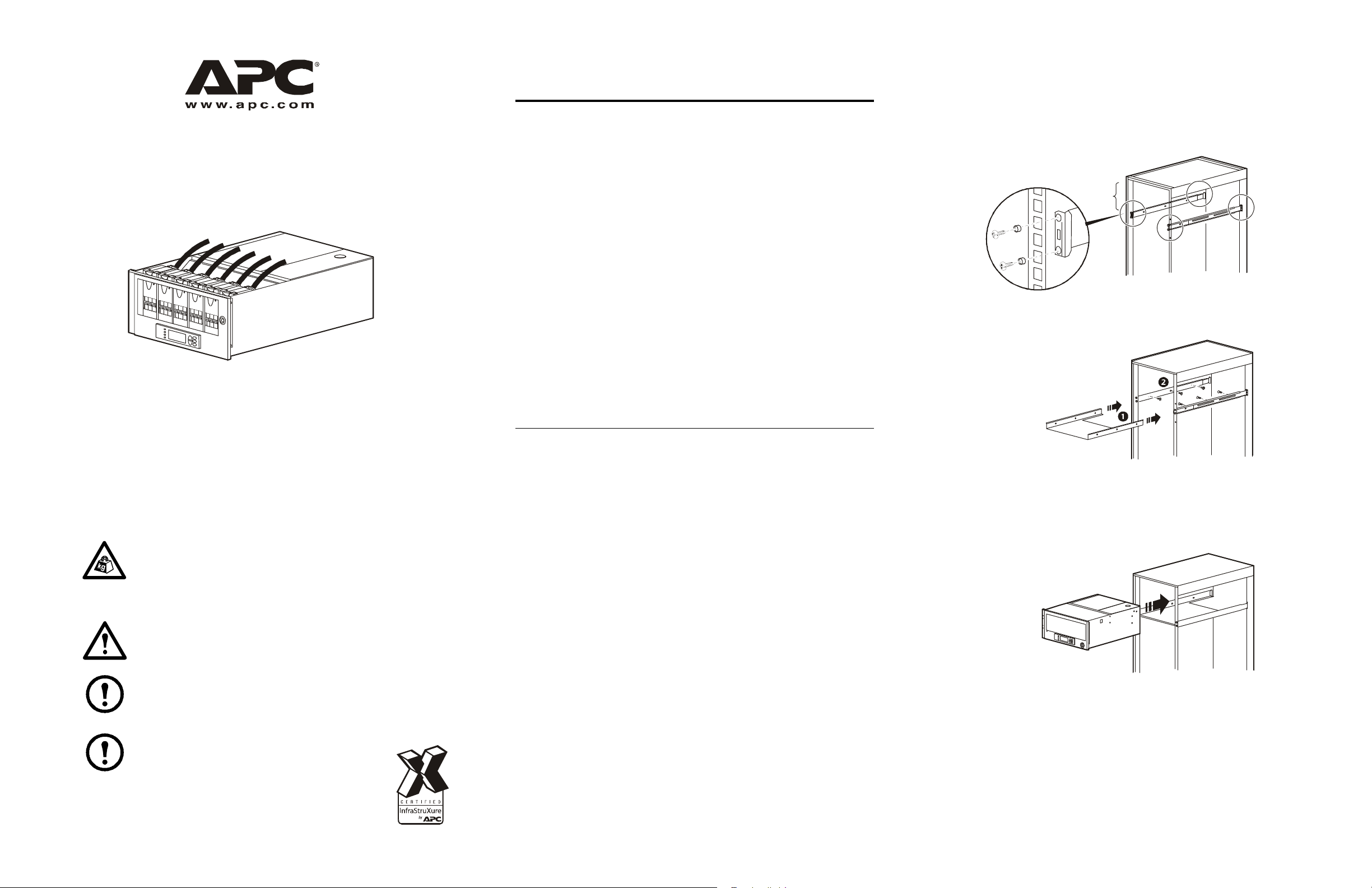
How to install the PDU
Install the mounting rails in the enclosure by using the screws
1
provided. The PDU requires a 5U space from the top of the
enclosure.
Slide the support tray into the mounting rails and secure it with the
2
screws provided.
This manual contains important instructions for the modular rack-mount
Power Distribution Unit (PDU) that should be followed during
installation and maintenance of this unit.
Handling Safety
Heavy: To prevent back injury, two or more people are
required to install the PDU in a rack.
Electrical Safety
Warning: To reduce risk of electric shock or injury to
persons, disconnect all sources of power before servicing.
Note: Install the unit in accordance with the National and
Canadian Electrical Codes, and if applicable, local codes.
Note: To prevent arcing when removing an APC
Power Distribution Module (PDM) from the PDU,
set all PDMs to
under load.
OFF. Do not remove the modules
How to perform a Total Power Off
Set all the APC Power Distribution Modules (PDM) to the OFF
1
position.
Set the utility/mains circuit breaker to the OFF position.
2
If the utility/mains is an UPS, set the UPS and its circuit breaker
3
supplying this product to the
Disconnect the input conductors from the utility/mains or the UPS.
4
OFF position.
Slide the PDU on to the support tray and secure it to the front posts of
3
the enclosure with the screws provided.
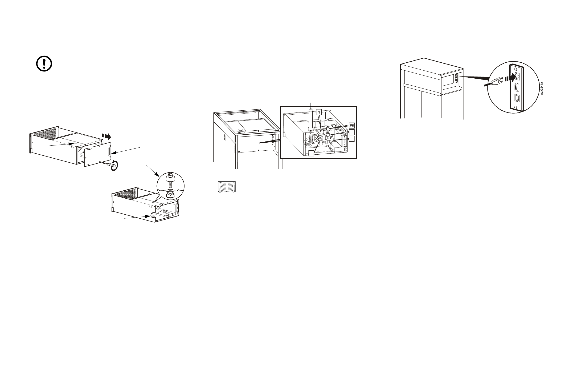
Slide the bracket tie-downs onto the guide pins on the side of the
4
PDU and secure the tie-downs to the back posts of the enclosure with
the screws provided.
pdx0242 a
990-3051C-001
12/2009
Page 2
Input cables
2
3
4
1
L3
L2
Conduits
2
Install input cables
Communication cables
Enlarge the knock out hole for larger conduit
Note: The cutout on the top (or bottom) cover plate may need
to be enlarged depending on the installation requirements.
If the conduit size for your installation is too large for the conduit
1
access knock out, the hole must be enlarged.
Loosen the seven screws and remove the back panel.
2
Use an electrician’s punch to enlarge the knock out hole to the size
3
needed.
pdx036 3a
Loosen the seven screws and remove the back panel to gain access to
1
the compression terminals (the top and bottom cover plates can be
removed if necessary for easier access).
Connect the Protective Earth/Ground (PE/G), neutral (N), and line
2
(L1, L2, and L3) conductors to the appropriate compression
terminals and conduits.
Reinstall the any panels that were removed.
3
Connect one end of the communication cable to the port on the back of
the unit and the other to the local area network.
L1
pdx0365a
If power is run from the bottom of the rack, enlarge the knock out
4
hole in the bottom of the unit.
Please refer to the Power Distribution Modules Installation
sheet for information on how to install APC Power
Distribution Modules (PDMs).
2
Page 3

Specifications
Input conductors
This product is rated 200 A. It should be supplied with a circuit breaker
with a maximum rating of 200 A.
For North America, if supplied by a 200 A circuit breaker, it is
recommended that conductors are sized in accordance with Table 3.
For countries outside of North America, if supplied by a 200 A circuit
breaker, it is recommended that conductors are sized in accordance with
Table 4.
Note: Input conductors are to be torqued to 31.1 Nm
(275 lb-in) using a 8 mm (5/16 in) Allen (hexagonal) wrench.
Tab le 1
AC Input
Tab le 2
AC Output
Nominal voltage 230 V/400 V 3 PH
120 V/208 V 3PH
Maximum continuous current 200 A
Voltage configuration 3 W + N + PE or 3 x (1 W + N + PE),
based on attached APC Power
Distribution Modules
Full load rating 138 kW @ 400 V 3PH
72 kW @ 208 V 3 PH
Output power cable connections Various, based on attached APC Power
Distribution Modules
Output power cable lengths Various, based on attached APC Power
Distribution Modules
Maximum APC Power Distribution
Modules
6
Tab le 4
200 A, Conductors
Copper, PVC
Install.
Method
B1 Ø&N = 95 mm²
B2 Ø&N = 120 mm²
C Ø&N = 95 mm²
E Ø&N = 95 mm²
F Ø&N = 70 mm²
Insulation,
30°C Ambient
PE = 50 mm²
PE = 70 mm²
PE = 50 mm²
PE = 50 mm²
PE = 35 mm²
Copper, XLPE
or EPR
Insulation,
30°C Ambient
Ø&N = 70 mm²
PE = 35 mm²
Ø&N = 95 mm²
PE = 50 mm²
Ø&N = 70 mm²
PE = 35 mm²
Ø&N = 70 mm²
PE = 35 mm²
Ø&N = 50 mm²
PE = 25 mm²
Aluminum,
PVC Insulation,
30°C Ambient
Ø&N = 150 mm²
PE = 95 mm²
Ø&N = 240 mm²
PE = 120 mm²
Ø&N = 150 mm²
PE = 95 mm²
Ø&N = 120 mm²
PE = 70 mm²
Ø&N = 95 mm²
PE = 50 mm²
Aluminum,
XLPE or ERP
Insulation,
30°C Ambient
Ø&N = 95 mm²
PE = 50 mm²
Ø&N = 120 mm²
PE = 70 mm²
Ø&N = 95 mm²
PE = 50 mm²
Ø&N = 95 mm²
PE = 50 mm²
Ø&N = 70 mm²
PE = 35 mm²
Nominal voltage 400 V 3 PH
208 V 3 PH
Frequency 47-63 Hz
Voltage configuration 3 W + N + PE
Maximum upstream circuit breaker 200 A
Maximum continuous current 160 A
Maximum continuous current with
100% rated circuit breaker
Maximum main input conductor size 250 mcm
200A
Maximum power distribution poles 18
Tab le 3
200 A, 75°C Conductors
Wiring System Copper Aluminum
3 CCC, 30°C Ambient Ø&N = 3/0 AWG
G = 6 AWG
4 CCC, 30°C Ambient Ø&N = 4/0 AWG
G = 6 AWG
Ø&N = 4/0 AWG
G = 4 AWG
Ø&N = (2) 1/0 AWG
G = (2) 4 AWG
Notes
CCC = Current-Carrying Conductors
AWG = American Wire Gauge
kcmils = MCM = Thousands of Circular Mils
Ø = Phase conductor
N = Neutral conductor
G = Ground (Equipment Grounding) conductor
(2) = two conductors per terminal
Notes
Ø = Phase conductor
N = Neutral conductor
PE = Protective Earth conductor
PVC = Polyvinyl-chloride
XLPE = Cross-linked polyethylene
EPR = Ethylene propylene rubber
3
Page 4

Physical Dimensions, Environment and
Compliance
Physical Dimensions
Dimensions (HxWxD) Unit: 229 x 457 x 737 mm (9 x 18 x 29 in)
Shipping: 406 x 610 x 889 mm (16.5 x 24 x 36 in)
Weight Unit: 23.5 kg (52 lb)
Shipping: 34 kg (75 lb)
Environment and Compliance Section
Operating Environment Protected from water and conductive contaminants
Temperature Operating: 0 to 30°C (32 to 86° F)
Operating (derated): 0 to 40ºC (32 to 104ºF)
Storage: 0 to 45°C (32 to 113°F)
Humidity Operating: 0 to 95%, non-condensing
Storage: 0 to 95%, non-condensing
Certification Certified by VDE to IEC 60439-1
Regulatory Agency Approval
This equipment has been tested and found to comply with the limits for a Class
A digital device, pursuant to Part 15 of the FCC Rules. These limits are
designed to provide reasonable protection against harmful interference, when
the equipment is operated in a commercial environment. This equipment
generates, uses, and can radiate radio frequency energy and, if not installed
and used in accordance with the Installation Guide, may cause harmful
interference to radio communications. Operation of this equipment in a
residential area is likely to cause harmful interference in which case the user
will be required to correct the interference at his own expense.
j
This Class A digital apparatus complies with Canadian ICES-003.
Cet appareil numérique de la classe A est conforme à la norme NMB003 du Canada.
This is a Class A Product. In a domestic environment this product may
cause interference in which case the user may be requires to take
adequate measures.
Conditional Short-Circuit
Current Rating (I
Rated Impulse Withstand
Voltage (U
Rated Diversity Factor 0.7
CC
)
CC
)
10 kA
4 kV
Note: APC’s products, similar to most computing products,
are designed to operate in an environment from 0 to 40°C.
Most data centers will maintain an operating temperature
between 0 to 30°C. Conductor Ampacity tables of the National
Electrical Code (NFPA 70) and IEC 60364-5-53 are based on
an environment from 0 to 30°C. If this product is installed in
an environment greater than 30°C, either this product’s current
rating will have to be derated, or the cross sectional area of the
conductors supplying it will have to increase, in accordance
with the derating factors of NFPA 70 and IEC 60364-5-53.
APC Worldwide Customer Support
For local, country-specific centers: go to www.apc.com/support/contact.
4
 Loading...