

Page 1
MGETM GalaxyTM 6000
50, 60 Hz
250 - 600 kVA
Installation manual
Single-unit UPS
Modular UPS
Parallel UPS with SSC
Frequency converters
Static Switch Cubicle
6739381EN/
Page 2

Page 2 - 6739381EN/JD
Page 3

Contents
Characteristics
Characteristics common to all cubicles ..................................................................... 4
Rectifier-inverter cubicles .......................................................................................... 5
Static Switch cubicles ............................................................................................... 5
External maintenance bypass cubicles ..................................................................... 5
"Pack Advance" cubicles........................................................................................... 5
Electrical parameters for selecting protective devices .............................................. 6
Electrical parameters for determining cable cross-sections .................................... 7
Heat losses ............................................................................................................. 7
Installation
Handling .................................................................................................................. 10
Positioning the cubicles .......................................................................................... 10
Floor loads .............................................................................................................. 11
Cubicle layout ......................................................................................................... 11
Power circuit wiring diagrams ................................................................................. 12
Connection of power circuits ................................................................................... 16
Connection of "Media Contacts 9" standard auxiliary circuits ................................. 26
Connections between cubicles ............................................................................... 27
Connections between
cubicle ..................................................................................................................... 29
Connection of "Media Contacts 15" additional auxiliary circuits.............................. 30
Connection of the battery "Temperature Monitor" ................................................... 31
Connection of the LED remote indications unit ....................................................... 33
Connection of "Tele Monitor" remote control and indication unit ............................ 33
Link to an IBM AS/400
Final installation steps ............................................................................................. 34
rectifier-inverter cubicles and external maintenance bypass
®
computer .......................................................................... 33
Appendix
Mains 2 line protection ............................................................................................ 35
Cubicle mounting and connection for 600kVA UPSs .............................................. 36
Cubicle mounting and connection for 2000kVA Static Switch Cubicles .................. 40
Details of earthing connections in the various cubicles .......................................... 43
TM
All MGE
GalaxyTM 6000 products are protected by patents. They implement original APC by Schneider Electric technology
not available to other manufacturers.
To take into account evolving standards and technology, equipment may be modified without notice. Indications concerning
technical characteristics and dimensions are not binding unless confirmed by APC by Schneider Electric.
This document may be copied only with the written consent of APC by Schneider Electric. Authorized copies must be marked
"APC by Schneider Electric MGE
® : IBM AS/400 is a registered trademark of the International Business Machines Corporation.
TM
GalaxyTM 6000 Installation Manual nr 6739381EN".
6739381EN/
Page 4
Characteristics
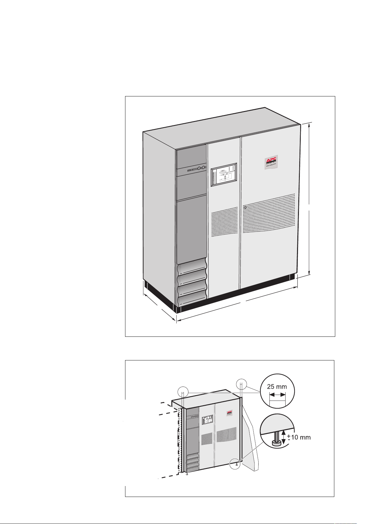
Characteristics common to all cubicles
TM
location on their pallets,
TM
MGE
GalaxyTM 6000 cubicles can be
moved short distances using a forklift or
pallet-mover when the front, rear and
side base panels are not mounted. The
forks can be inserted from all four sides
into 100 mm
+/– 10 mm high openings;
◗ the unadjusted cubicle height (H) is
1900/2000 mm; after lifting the cubicle,
the height can be adjusted +/– 10 mm
by screwing in or out the four feet;
◗ the bearing surface corresponds to
the area of the four cylindrical foot pads
(60 mm diameter) positioned in each
corner of the cubicle;
◗ the cubicle depth (D) is 840 mm
(800 mm without doors and panels);
◗ operating temperature range for
rectifier-inverter, frequency converter or
Static Switch Cubicles: 0°C to 35°C at
rated output (40°C for a maximum of
8 hours) and 30°C maximum for
overload conditions. Operation outside
the specified temperature range will
reduce service life;
◗ relative humidity: 95% maximum;
◗ maximum operating altitude without
derating: 1000 m;
◗ connection via the bottom for
rectifier-inverter cubicles, or via the top
with the addtion of an optional duct that
can be installed on the right side of the
cubicle. The auxiliary and Static Switch
Cubicles are designed for connections
via the top or bottom.
◗ the connection cables may be run in
three ways:
◗◗ in a trench running under the
cubicles,
◗◗ under a false floor,
◗◗ on the floor under the cubicles, in the
free space equal to the height of the
feet; in this case the cables should be
run side by side to avoid blocking the
flow of air for ventilation.
◗ the intercubicle connection cables
are not supplied (except for the wires
for auxiliary interconnections);
◗ normally the cubicles do not have to
be secured to the floor; the footpads
nevertheless have holes with an
average depth of 12 mm designed for
the fitting of M16 anchor bolts;
◗ the cubicle doors are secured by
Ronis locks (key 405).
MGE
GalaxyTM 6000 UPS: example of a rectifier-inverter cubicle◗ After moving them to their installation
A
V
k
5
%
2
0
1
2
1
.
n
i
M
%
0
Y
X
A
L
A
G
IQ
E
L
L
A
S
e
m
o
H
s
rm
la
A
e
lin
n
O
d
n
e
r
T
C
l A
a
rm
s
o
ic
t
N
is
t
a
t
S
r
ie
if
t
c
e
R
y
r
te
at
B
r
e
t
r
e
v
A
In
s
as
p
y
B
s
s
a
p
y
B
t
u
tp
u
O
p
u
t
e
S
5
r
u
o
H
0
A
V
k
0
0
4
0
0
0
6
k
c
a
B
d
e
l
e
t
b
c
a
e
il
t
a
o
v
r
p
A
d
a
o
L
1Q
Q
1
F
Q
S
4
Q
C
P
B
3
Q
0
0
1
%
0
0
1
%
80
%
0
5
%
0
5
0
l
e
v
e
l
d
a
o
L
0
e
m
i
T
p
u
5N
d
a
o
t
L
n
e
m
ip
u
q
e
5
0
0
/2
5
/0
0
3
2
3
:
4
2
:
5
1
Galaxy 6000
com
ps.
u
ge
m
w.
w
w
H
L
P
Page 4 - 6739381EN/JD
Page 5
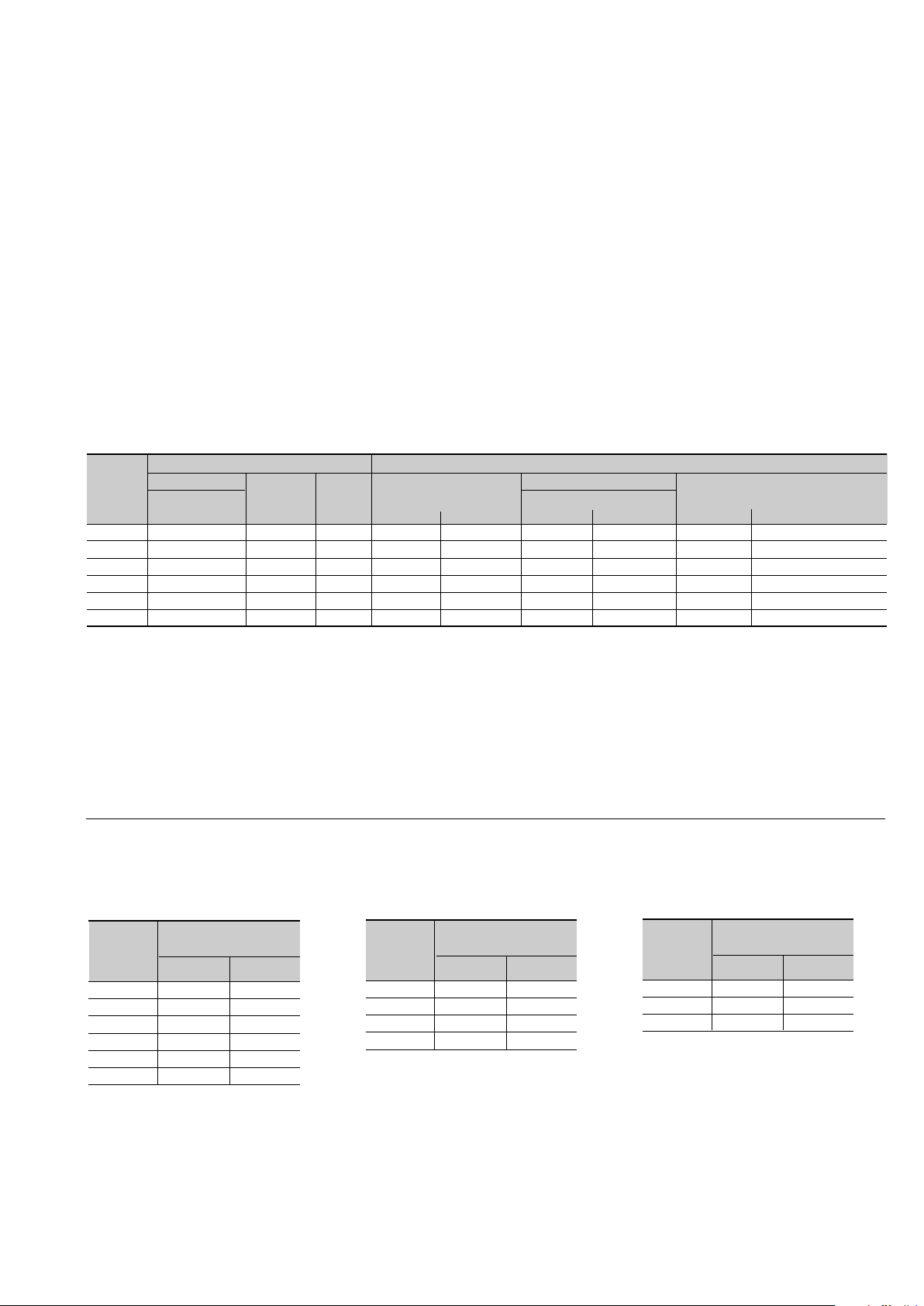
Rectifier-inverter cubicles
Characteristics (cont.)
The parameters given in the table
opposite can be used to determine the
required rating of a single-unit or
modular UPS, a frequency converter, or
a parallel UPS with SSC.
Static Switch cubicles
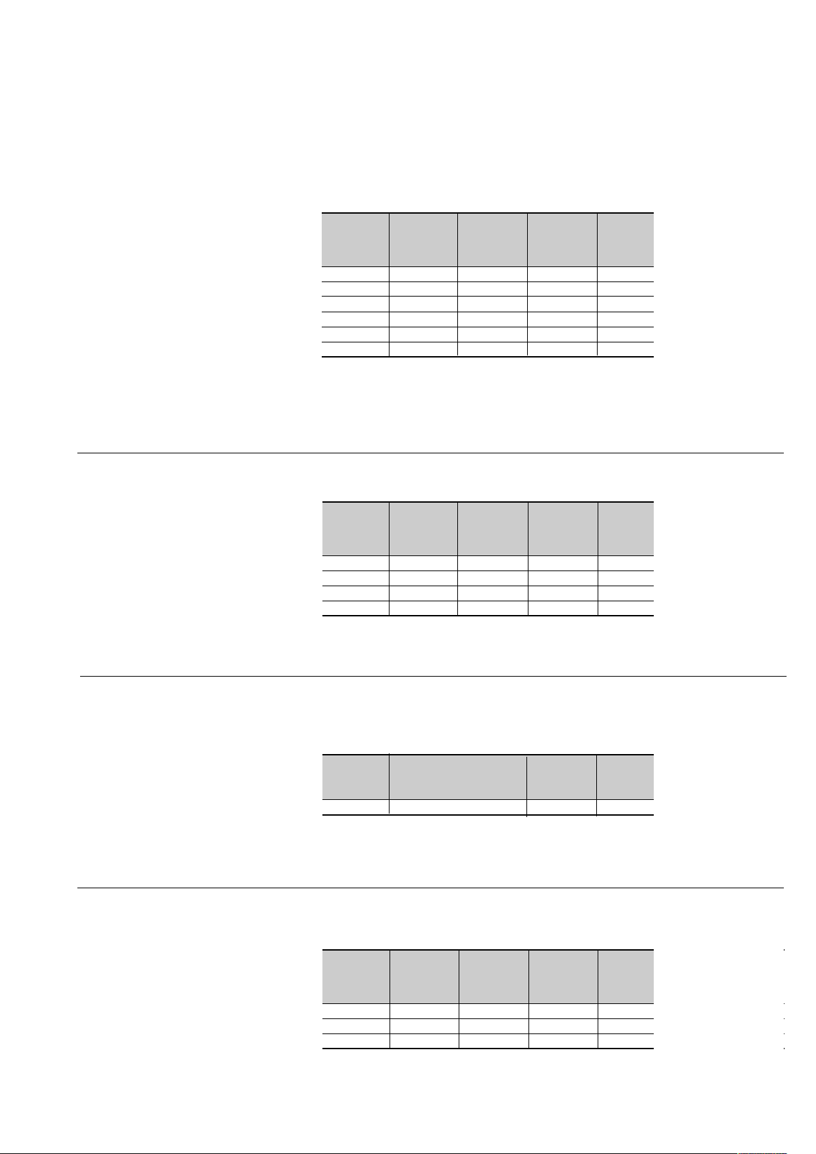
Characteristics of rectifier-inverter cubicles
rated cubicle cubicle cubicle maximum
inverter width W height H depth D weight
output in mm (1) in mm in mm in kg
in kVA
250 1600 1900 ± 10 840 1650
300 1600 1900 ± 10 840 1650
400 1600 1900 ± 10 840 2030
450 1600 2000 ± 10 840 2070
500 1600 2000 ± 10 840 2205
600 3600 1900 ± 10 840 3500
(1) 25 mm must be added on each side to the indicated cubicle width, i.e. 50 mm in all per cubicle. This
applies to all cubicle installation cases.
When installing several cubicles, allow for a tolerance of 0/+3mm per metre.
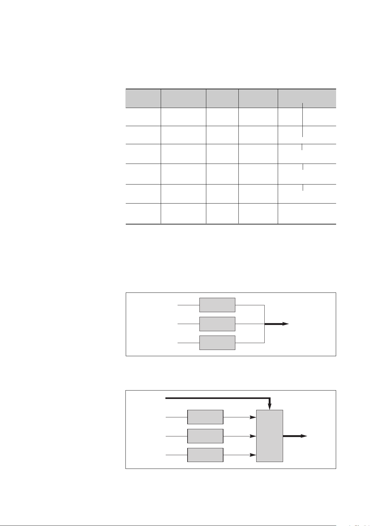
Characteristics of Static Switch Cubicles
rated cubicle cubicle cubicle maximum heat
SSC width W height H depth D weight losses (2)
output in mm (1) in mm in mm in kg
in kVA in kW in cal./s
500 1000 1900 ± 10 840 350 2.9 696
800 1000 1900 ± 10 840 500 3.7 888
1200 1600 1900 ± 10 840 1000 < 0.5 < 120
2000 2450 1900 ± 10 840 1710 < 0.5 < 120
(1) 25 mm must be added on each side to the indicated cubicle width, i.e. 50 mm in all per cubicle. This
applies to all cubicle installation cases.
When installing several cubicles, allow for a tolerance of 0/+3mm per metre.
External maintenance bypass cubicles
Characteristics of external maintenance bypass cubicles
(Modular UPS with external maintenance bypass)
rated cubicle cubicle cubicle maximum
bypass width W height H depth D weight
in kVA in mm (1) in mm in mm in kg
1200 1200 1900 ± 10 840 450
(1) 25 mm must be added on each side to the indicated cubicle width, i.e. 50 mm in all per cubicle. This
applies to all cubicle installation cases.
When installing several cubicles, allow for a tolerance of 0/+3mm per metre.
"Pack Advance" cubicles
Characteristics of "Pack Advance"Cubicles
rated cubicle cubicle cubicle maximum heat
SSC width W height H depth D weight losses (2)
output in mm (1) in mm in mm in kg
in kVA in kW in cal./s
300 400 1900 ± 10 840 335 2.9 696
400 400 1900 ± 10 840 440 3.7 888
450 400 1900 ± 10 840 440 < 0.5 < 120
(1) 25 mm must be added on each side to the indicated cubicle width, i.e. 50 mm in all per cubicle. This
applies to all cubicle installation cases.
When installing several cubicles, allow for a tolerance of 0/+3mm per metre.
6739381EN/
Page 6
Characteristics (cont.)
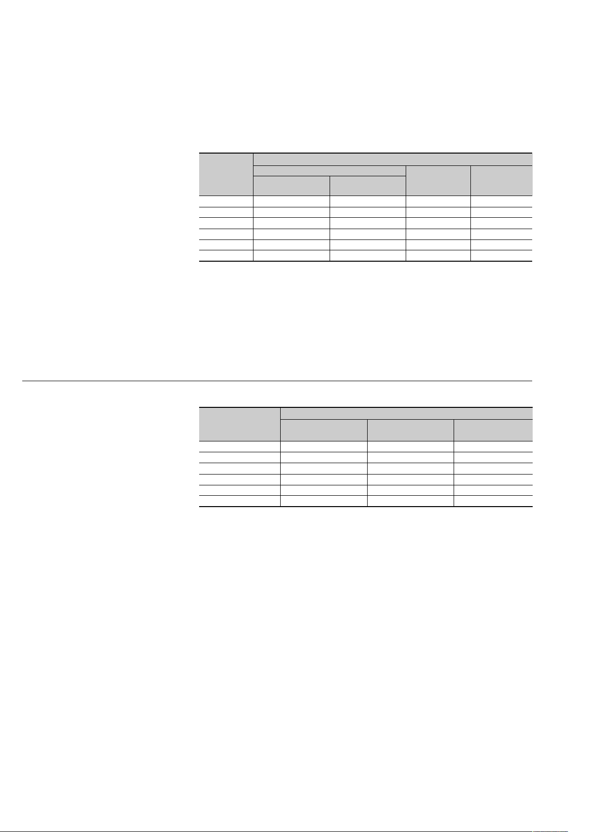
Electrical parameters for selecting protective devices
The parameters given in the table
opposite can be used to determine the
required rating of the source side
protective circuit breaker on Mains 1 of
a single-unit or modular UPS, a
frequency converter, or a parallel UPS
with SSC.
Important:
It is essential to choose the type of
circuit breaker according to its breaking
capacity and the prospective shortcircuit current at its place of installation.
Note:
For Mains 1 power supply voltages of
380, 400 and 415V, the Mains 1 current
is the same because it is a function of
the DC voltage.
The parameters given in the table
opposite can be used to determine the
required rating of the source side
protective circuit breaker on the Mains
2 line for a single-unit or modular UPS.
Important:
◗ It is essential to choose the type of
circuit breaker according to its breaking
capacity and the prospective shortcircuit current at its place of installation.
This choice must also be made so as to
protect the static switch semiconductors
and ensure discrimination with respect
to the UPS output fuses (refer to
"appendix" chapter).
◗ For an installation with a Static
Switch Cubicle, the Mains 2 currents
indicated in the table must be multipled
by the number of parallel-connected
rectifier-inverter cubicles required to
supply the load power (i.e. without
taking redundant rectifier-inverter units
into account).
Remark:
If the installation includes a transformer
on the Mains 2 input, allow for the
inrush current caused by magnetization
of the transformer windings.
Electrical parameters for Mains 1
rated
inverter
output
in kVA
250 447 407 509 611
300 537 490 612 734
400 727 654 818 981
450 775 735 919 1102
500 920 821 1026 1231
600 1089 981 1226 1472
(1) the rated Mains 1 currents (In) have been
determined for a rated phase-to-phase voltage of
380V to 415V, a battery with a 15 minute backup
time (206 cells at 2V per cell, i.e. 412V) and at the
beginning of its recharge cycle, and full rated load
with a power factor of 0.8.
(2) the rated Mains 1 currents (In) have been
determined for a minimum float charging voltage of
423V and full rated load with a power factor of 0.8.
Mains 1 current
rated current In for unit:
with battery at start without battery (2)
of charge cycle (1)
(3) the Mains 1 currents given for an overload of
25% or 50% are maximum values. They have been
determined for a battery drawing the minimum float
charging voltage and a load power factor of 0.8.
When choosing the circuit breaker rating, use the
"rated current" column and check that the circuit
breaker tripping curves are compatible with the
values in the overload columns.
for 25% for 50%
overload (3) overload (3)
Electrical parameters for Mains 2 (415V)
rated Mains 2 current (1)
inverter output rated current for 25% for 50%
in kVA In overload overload
250 347 433 519
300 416 519 624
400 556 695 834
450 649 811 973
500 722 902 1083
600 866 1082 1300
(1) the Mains 2 currents have been determined for
a rated phase-to-phase voltage of 415V, a load
power factor of 0.8 and for full rated load as well as
overloads of 25% or 50%. When choosing the
circuit breaker rating, use the "rated curent"
column and check that the circuit breaker tripping
curves are compatible with the data in the overload
columns. For a Mains 2 voltage of 380V, multiply
the currents indicated in this table by 1.09.
For a Mains 2 voltage of 400V, use the table in
another language version of this manual.
Page 6 - 6739381EN/JD
Page 7
Electrical parameters for determining cable cross-sections
Characteristics (cont.)
◗ this table has been drawn up for
rated phase-to-phase Mains and load
voltages of 415V. For voltages of 380V,
multiply the currents for Mains 2 and
load by 1.09; for voltages of 400V, use
the table in another language version of
this manual;
◗ the current values and cable cross-
sections for Mains 1 are given for full
rated load with a power factor of 0.8
and a battery consuming its minimum
◗ the battery current values and cable
cross-sections have been determined
for a battery at the end of a charge
cycle;
◗ the current values and cable sections
for Mains 2 and load are given for full
rated load with a power factor of 0.8.
For frequency converters, the
parameters concerning Mains 2 are not
applicable.
The load parameters common to all the
converters are given in the table below.
For a parallel UPS, the parameters for
Mains 2 and load are also provided in
the table below.
For a modular UPS, the parameters
for Mains 2 and load are also
provided in the table below.
float charging voltage;
Parameters for single-unit UPS cables
rated
inverter
output
in kVA
250 407 361 630 185 300 150 240 240 2 x 185
300 490 433 758 240 2 x 150 240 2 x 150 240 2 x 240
400 654 577 1013 2 X 185 2 x 300 2 x 150 2 x 240 2 x 185 3 x 185
450 735 649 1137 2 X 185 2 X 300 2 X 185 2 x 300 2 x 185 2 x 300
500 821 722 1252 2 x 240 4 x 185 2 X 185 2 x 300 3 x 150 3 x 240
600 981 866 1519 3 x 240 4 x 240 2 X 240 4 x 185 3 x 185 2 x 400
(1) the rated Mains 1 currents (In) have been
determined for a minimum float charging voltage of
423V and full rated load with a power factor of 0.8.
line currents absorbed in Amps cross-sectional area of Cu cables in mm2 (2)
Mains 1 415V battery Mains 1 415V battery
with or without
battery (1)
Mains 2 with or without battery Mains 2 and load
and load Copper Aluminium Copper Aluminium Copper Aluminium
(2) the cable cross-sections are given for copper
conductors. They are calculated according to
permissible temperature rise and allow for line
voltage drops over a maximum length of 100 m
(AC circuits) or 25 m (DC circuits if cables not
provided). For greater lengths, the cross-sections
should be chosen to limit voltage drops to 3% (AC)
or 1% (DC).
NF C 15-100 authorizes a maximum of 4
cables per phase.
Heat losses
rectifier-inverter cubicles
rated heat
inverter losses (1)
output
in kVA in kW in cal./s
250 13,5 3220
300 17,5 4170
400 23 5480
450 25 5960
500 30 7150
600 32,8 7830
(1) the indicated heat losses are those produced
by the unit at full rated load and with the battery
float charging. They must be taken into account
when dimensioning the air conditioning system.
The cubicles are cooled by forced ventilation.
The air enters via the doors and grids at the bottom
and is discharged via the roof.
static switch cubicles
rated heat
SSC losses (1)
output
in kVA in kW in cal./s
500 2,9 696
800 3,7 888
1200 < 0,5 < 120
2000 < 0,5 < 120
(1) the indicated heat losses are those produced
by the unit at full rated load when operating on
Mains 2. They are not to be taken into account
when dimensioning the air conditioning system.
The cubicles are cooled by forced ventilation.
"Pack advance" cubicles
rated heat
inverter losses (1)
output
in kVA in kW in cal./s
300 2,2 525
400 2,6 620
450 2,6 620
(1) the indicated heat losses are those produced
by the unit at full rated load and with the battery
float charging. They must be taken into account
when dimensioning the air conditioning system.
The cubicles are cooled by forced ventilation.
The air enters via the doors and grids at the bottom
and is discharged via the roof.
6739381EN/
Page 8
Characteristics (cont.)
The table opposite serves as an
example for an installation comprising
up to four frequency converters or four
parallel UPSs with a centralised SSC.
◗ for installations with redundant units,
take into account only the units
required to supply the load power
(e.g. for an installation made up of 3
parallel-connected rectifier-inverter
cubicles, one being redundant, only 2
rectifier-inverter cubicles are used to
determine Mains 2 and load currents
and cable cross-sections);
◗ this table has been drawn up for
rated phase-to-phase Mains 2 and load
voltages of 415V and full rated load
with a power factor of 0.8. For voltages
of 380 or 400V, multiply the indicated
currents by 1.09 and 1.04 respectively,
then modify the cable cross-sections
accordingly if necessary.
The cable cross-sections in this table
are for the parts illustrated in bold on
the following block diagrams
(installation examples, figures 1 and 2).
Parameters for Mains 2 and load cables for an installation comprising
frequency converters or parallel UPSs with a centralised SSC.
rated inverter number of total UPS Mains 2 or load cable cross-section (1)
output parallel-connected rated output line current in mm
in kVA inverters in kVA in Amps Copper Aluminium
250 2 500 722 2 x 185 2 x 300
300 2 600 866 2 x 240 4 x 185
400 2 800 1298 4 x 185 4 x 300
450 2 900 1154 4 x 240 4 x 400
500 2 1000 1444 4 x 240 4 x 400
600 2 1200 1731 Please consult us*
(1) cable cross-sections are given for copper
conductors of the U1000 R02V type. They are
calculated according to permissible temperature
rise and allow for line voltage drops over a
3 750 1082 3 x 300 4 x 240
4 1000 1444 4 x 240 4 x 400
3 900 1299 4 x 240 4 x 400
4 1200 1732 Please consult us*
3 1200 1947 Please consult us*
4 1600 2596 Please consult us*
3 1350 1731 Please consult us*
4 1800 2308 Please consult us*
3 1500 2164 Please consult us*
4 2000 2888 Please consult us*
3 1800 2598 Please consult us*
4 2400 3462 Please consult us*
maximum length of 100 m. For greater lengths,
the cross-sections should be chosen to limit
voltage drops to 3%.
NF C 15-100 authorizes a maximum of 4
cables per phase.
2
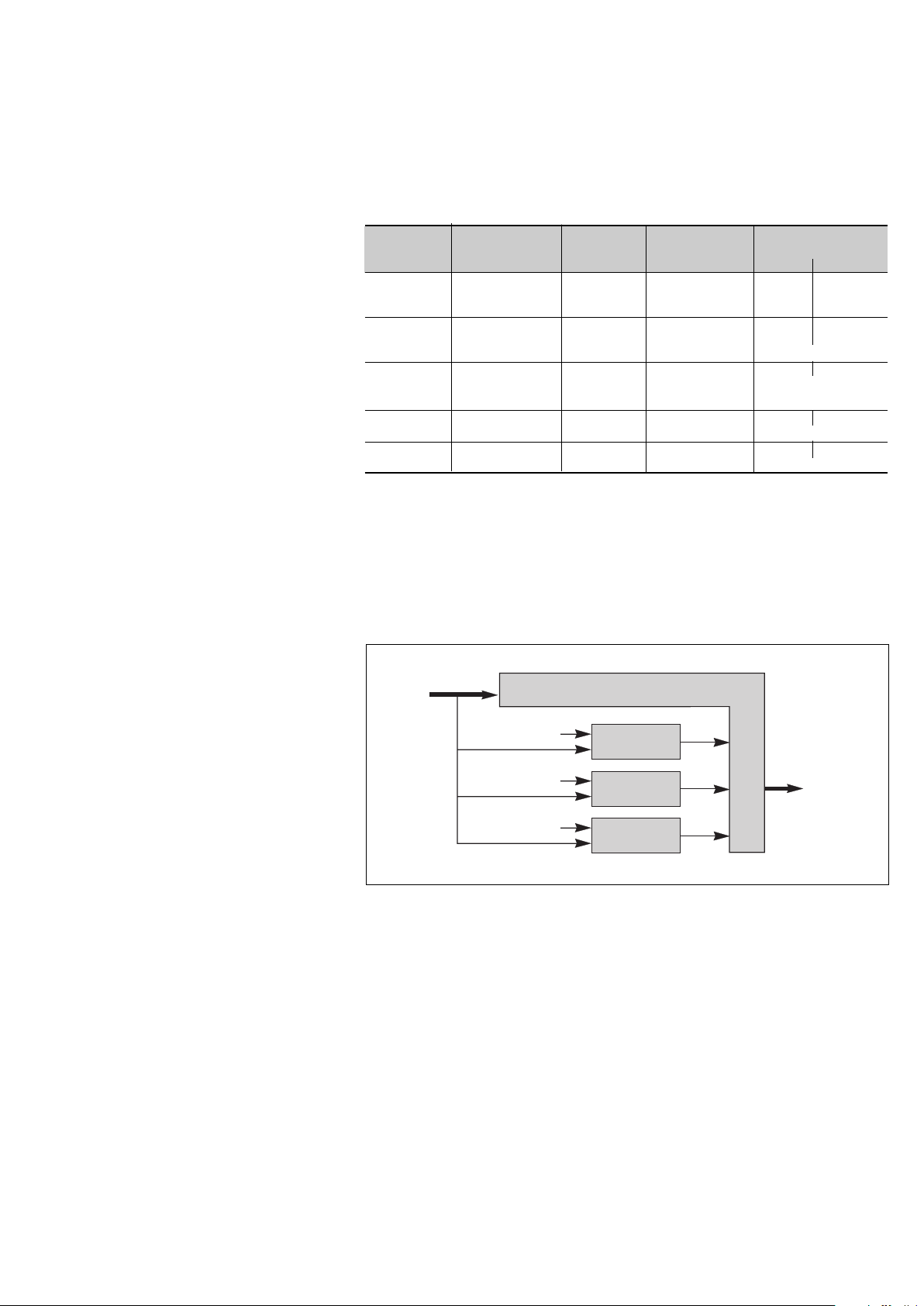
Installation with parallel frequency converters
mains 1
mains 1
mains 1
inverter 1
inverter 2
inverter 3
Fig. 1
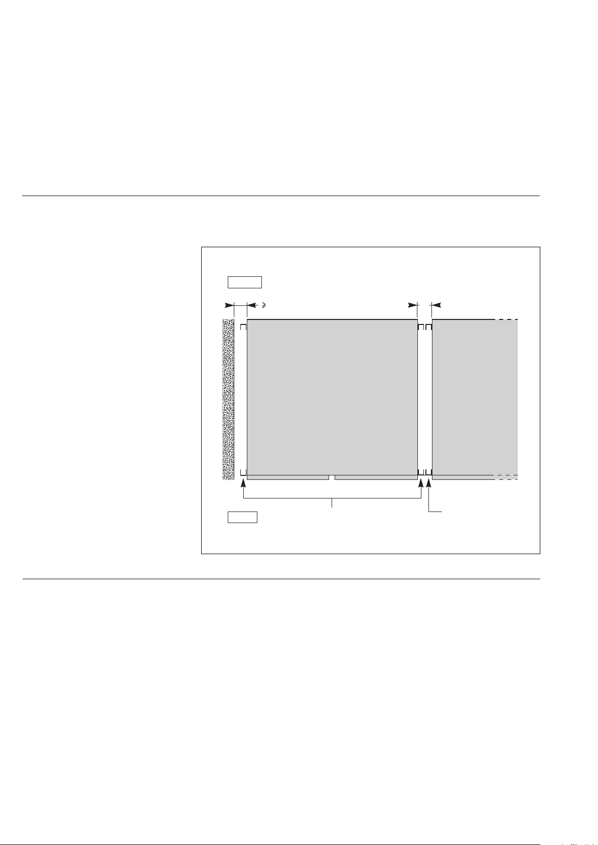
Installation with parallel UPSs with a centralised SSC
mains 2
mains 1
mains 1
mains 1
inverter 1
inverter 2
inverter 3
static
switch
cubicle
load
load
Page 8 - 6739381EN/JD
Fig. 2
Page 9
Characteristics (cont.)
The table opposite serves as an
example for an installation with up to
four modular UPSs with an external
maintenance bypass.
◗ for installations with redundant units,
take into account only the units
required to supply the load power
(e.g. for an installation made up of 3
parallel-connected rectifier-inverter
cubicles, one being redundant, only 2
units are used to determine the
currents on the maintenance bypass
line and the load, and the crosssectional areas of cables);
◗ this table has been drawn up for
rated phase-to-phase Mains 2 and load
voltages of 415V and full rated load
with a power factor of 0.8. For voltages
of 380 or 400V, multiply the indicated
currents by 1.09 and 1.04 respectively,
then modify the cable cross-sections
accordingly if necessary.
The cable cross-sections in this table
are for the parts illustrated in bold on
the following block diagrams
(installation example, figure 3);
◗ important. In an installation with an
external maintenance bypass, the
power cables between each UPS and
the upstream protection devices
must be the same length. The same
holds for the power cables between
each UPS cubicle and the external
maintenance bypass.
Parameters for connection of the external maintenance bypass circuit and the
load in an installation comprising modular UPSs
rated inverter number of total UPS Mains 2 or load cable cross-section
output parallel-connected rated output line current (1) in mm
in kVA inverters in kVA in Amps Copper Aluminium
250 2 500 722 2 x 185 2 x 300
300 2 600 866 2 x 240 4 x 185
400 2 800 1154 4 x 185 4 x 300
450 2 900 1299 4 X 240 4 x 400
500 2 1000 1444 4 X 240 4 x 400
(1) cable cross-sections are given for copper
conductors of the U1000 R02V type. They are
calculated according to permissible temperature
rise and allow for line voltage drops over a
maximum length of 100 m. For greater lengths,
the cross-sections should be chosen to limit
voltage drops to 3%.
3 750 1082 3 x 300 4 x 240
4 1000 1444 4 x 240 4 x 400
3 900 1299 4 x 240 4 x 400
4 1200 1732 Please consult us*
3 1200 1731 Please consult us*
4 1600 2308 Please consult us*
3 1350 1948 Please consult us*
3 1500 2166 Please consult us*
NF C 15-100 authorizes a maximum of 4
cables per phase.
2
Installation comprising modular UPSs with an external maintenance bypass
maintenance Bypass cubicle
Fig. 3
mains 1
mains 2
mains 1
mains 2
mains 1
mains 2
inverter 1
inverter 2
inverter 3
load
6739381EN/
Page 10
Installation
(to be carried out by qualified personnel only)
Handling
Unpacked cubicles may be moved
using a forklift from the front or from the
back. Distances must not exceed a few
meters.
Positioning the cubicles
(for 600 kVA UPSs, see the appendix
as well)
◗ prior to moving the cubicles to their
final position, remove the packing
material and withdraw the base panels
from the space on the side created by
the spacing uprights. The panels will be
installed at the end of the installation
procedure;
◗ spacing uprights on the sides of the
cubicles create a 50 mm clearance
when cubicles are positioned next to
each other, enabling users to open the
doors (see figure 4). If a cubicle is
installed next to a wall, leave additional
space so that the cubicle is 50 mm from
the wall;
◗ when the spacing uprights are not
required (cubicles are not positioned
next to a wall or another cubicle), they
may be removed:
◗◗ loosen the four screws securing the
upright,
◗◗ lift the upright and pull it free,
◗◗ replace the long gold-coloured
screws with the black screws supplied
in a bag attached to the cable terminals
in the cubicle;
◗ adjust the height of the feet until the
first cubicle is perfectly vertical; adjust
the feet of the subsequent cubicles so
that the all the doors are perfectly
aligned.
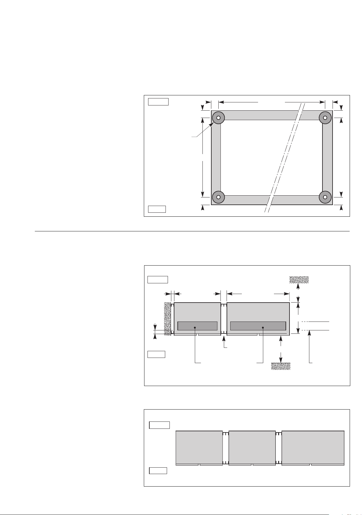
Side clearances provided by the spacing uprights
rear
50
cubicle 1
front
spacing uprights
of cubicle 1
Fig. 4
50
cubicle 2
spacing uprights
of cubicle 2
Page 10 - 6739381EN/JD
Page 11
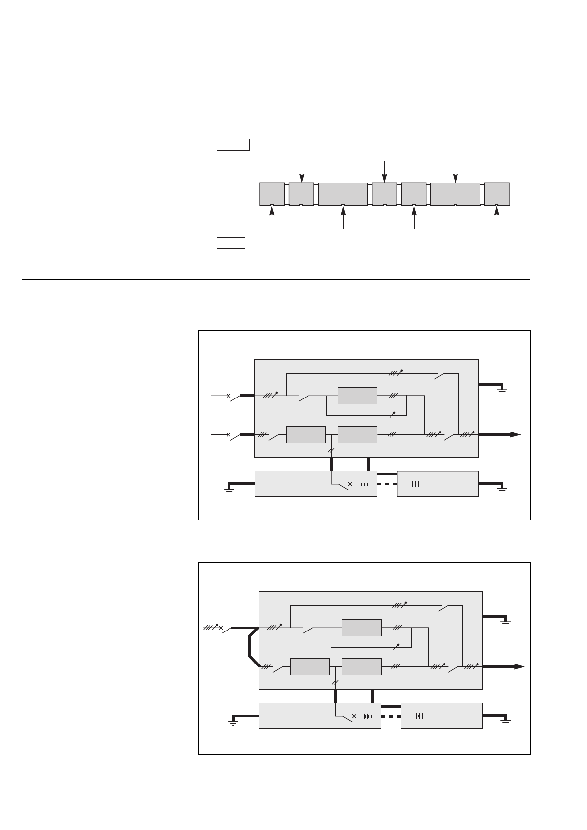
Floor loads (figure 5)
Installation (cont.)
◗ the floor supports the weight of each
Cubicle footpads
cubicle via the four 60 mm diameter
pads at the bottom of the feet screwed
rear
33 33
into the corners of the frame;
◗ the exact locations of the footpads
33
are indicated in the figure;
◗ normally the cubicles do not have to
be secured to the floor; the footpads
nevertheless have holes with an
average depth of 12 mm designed for
the fitting of M16 anchor bolts;
◗ to determine the stresses applied by
four 60 mm dia.
footpads with
12 mm average
depth holes for
M16 anchor bolts
736
the cubicle feet on the floor, divide the
cubicle weight (see the first 3 tables of
this manual) by the total area of the 4
footpads (110 cm
2
).
front
Fig. 5
Cubicle layout on false floor or normal floor (figures 6, 7, 8)
◗ the cubicles can be installed directly
up against the rear wall;
◗ an overall clearance of 400 mm must
be left above the entire surface of the
cubicles for ventilation;
◗ a side clearance of 25 mm is
provided by the vertical bars on the
sides of the cubicles to allow door
opening. For cubicles mounted side by
side, the two adjacent bars ensure an
inter-cubicle clearance of 50 mm;
◗ a minimum clearance of 1000 mm is
required in front of the cubicles to allow
complete opening of the doors and
easy access for maintenance work
(replacement of subassemblies);
◗ for extended battery backup times or
high output systems, the UPS may
have several battery cubicles (see the
table at the end of the previous
chapter). If this is the case, install the
battery cubicles on the left side of the
rectifier-inverter cubicle with the cubicle
containing the battery circuit breaker
QF1 closest to the rectifier-inverter
cubicle (figure 7);
◗ when an auxiliary cubicle is included
in the UPS, it should be installed to the
left of the battery cubicle(s);
◗ connection via the bottom
The connection cables may be run in
three ways:
◗◗ in a cable trench running underneath
the front of the cubicles (see trench
dimensions and layout in figure 6),
◗◗ under a false floor.
A cutout must in this case be made in
the floor for cable entry (see figure 6 for
dimensions),
Layout for a single-unit UPS with one battery cubicle
rear
>25
80
cubicle width W
(see table)
battery cubicle
front
cutouts necessary for
cable entry from underneath
a false floor:
200 mm x (W – 160 mm)
Fig. 6
Layout for a single-unit UPS with several battery cubicles
rear
battery cubicle 2
front
Fig. 7
50
cubicle width W
(see table)
rectifier-inverter cubicle
spacing uprights
battery cubicle 1
containing battery
circuit breaker QF1
cubicle width
less 66 mm
> 1000
can equal 0
800
location
of trench
under cubicles
(if applicable)
rectifier-inverter cubicle
33
3333
6739381EN/
Page 12
Installation (cont.)
◗◗ on the floor under the cubicles, in the
free space equal to the height of the
feet. In this case the cables should be
run side by side to avoid blocking the
flow of air for ventilation. The cables
exit from the rear or sides of the
cubicles;
◗ connection via the top
◗◗ the Static Switch, filter and auxiliary
cubicles are designed for connection
via the bottom or top,
◗◗ for the rectifier-inverter cubicles, a
special 400 mm wide connection duct
must be added to the right of the
cubicle to allow connection via the top.
Power circuit wiring diagrams
The single-wire diagrams for typical
UPS installations are given in figures 9
to 15. The heavy lines represent the
cables that must be connected
(see the table in the previous chapter
for the required cross-sectional areas of
the cables).
Note:
◗ for frequency converters, the input
and output frequencies may be different
(50 or 60Hz);
◗ for frequency converters without
batteries, ignore the battery cubicles
and the + and - cables shown in the
diagram.
Special case:
The UPSs can be optionally supplied
with the neutral conductor not
interrupted by switches Q4S, Q3BP
and Q5N.
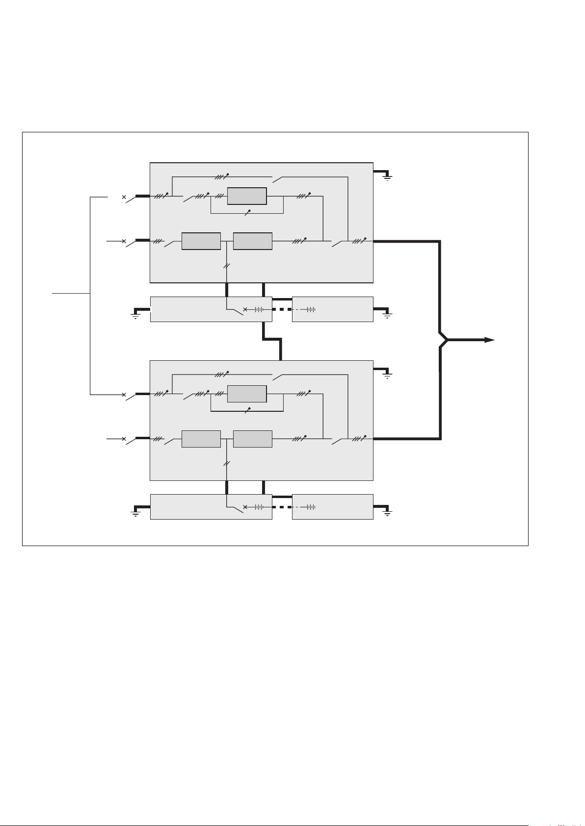
Layout for an installation with two parallel UPSs and a centralised SSC
rear
front
auxiliaries
cubicle 2
(if applicable)
battery
cubicle(s) 2
rect./inv.
cubicle 2
auxiliaries
cubicle1
(if applicable)
battery
cubicle(s) 1
rect./inv.
cubicle 1
static switch
cubicle
Fig. 8
Diagram for a single-unit or single modular UPS with separate Mains 1 and 2
rectifier-inverter cubicle
Q3BP
mains 2
mains 1
earth
Q4S
Q1 Q5N
rectifier
charger
battery cubicle
beside the
rectifier-inverter cubicle
QF1
static
switch
inverter
+
frames interconnections for earthing
-
+
-
other battery
cubicles (if
applicable)
earth
load
earth
Fig. 9
Page 12 - 6739381EN/JD
Diagram for a single-unit or single modular UPS with common Mains 1 and 2
rectifier-inverter cubicle
Q3BP
mains
earth
mains 2
input
mains 1
input
Q4S
Q1 Q5N
rectifier
charger
battery cubicle
beside the
rectifier-inverter cubicle
QF1
static
switch
inverter
+
frames interconnections for earthing
+
-
-
other battery
cubicles (if
applicable)
earth
load
earth
Fig. 10
Page 13
Installation (cont.)
Diagram for a frequency converter with batteries
rectifier-inverter cubicle
mains 1
earth
Q1 Q5N
rectifier
charger
battery cubicle
beside the
rectifier-inverter cubicle
QF1
inverter
+
frames interconnections for earthing
-
+
-
Fig. 11
Diagram for a frequency converter without batteries
rectifier-inverter cubicle
mains 1
Q1 Q5N
rectifier
charger
inverter
Fig. 12
Example of a 2 parallel UPS rectifier-inverters with SSC
other battery
cubicles (if
applicable)
load
earth
earth
load
earth
Note:
Both the rectifier-inverter cubicles and
the Static Switch Cubicle can be
supplied from a common mains, in
which case there is only one upstream
circuit breaker (same as the case of a
single-unit UPS with a common Mains
1 and 2).
mains 2
mains 1
earth
mains 1
earth
Static Switch Cubicle
Q3BP
Q4S
rectifier-inverter cubicle 1
Q1 Q5N
rectifier
charger
battery cubicle
beside rectifierinverter cubicle 1
rectifier-inverter cubicle 2
Q1 Q5N
rectifier
charger
battery cubicle
beside rectifierinverter cubicle 2
static
switch
inverter 1
QF1
inverter 2
QF1
frames interconnection for earthing
frames interconnections for earthing
+
-
frames interconnections for earthing
frames interconnections for earting
+
-
+
+
Q5N
other battery
-
cubicles (if
applicable)
other battery
-
cubicles (if
applicable)
earth
load
inverter 1
output
inverter 2
output
earth
earth
earth
earth
Fig. 13
6739381EN/
Page 14
Installation (cont.)
Example of 2 multi-bypass modular UPS cubicles for redundancy (from 250 to 500kVA)
modular UPS cubicle 1
Q3BP
earth
mains 2
mains 1
earth
mains 2
mains 1
Q4S
Q1 Q5N
rectifier
charger
battery cubicle
beside rectifierinverter cubicle 1
modular UPS cubicle 2
Q4S
Q1 Q5N
rectifier
charger
static
switch
inverter 1
QF1
static
switch
inverter 2
frames interconnection for earthing
+
-
Q3BP
+
frames interconnection for earthing
-
other battery
cubicles (if
applicable)
inverter 1
output
earth
earth
inverter 2
output
load
Fig. 14
earth
battery cubicle
beside rectifierinverter cubicle 2
QF1
frames interconnection for earthing
other battery
+
-
+
-
cubicles (if
applicable)
earth
Page 14 - 6739381EN/JD
Page 15

Installation (cont.)
Example of an installation comprising three modular UPSs with an external maintenance bypass (from 250 to 500 kVA)
External
maintenance
bypass line
mains 2
mains 1
earth
mains 2
External maintenance bypass cubicle
Q3BP
modular UPS cubicle 1
Q4S
Q1 Q5N
rectifier
charger
battery cubicle
beside rectifierinverter cubicle 1
modular UPS cubicle 2
Q4S
static
switch
inverter 1
QF1
static
switch
frames interconnection for earthing
+
-
frames interconnection for earthing
+
other battery
-
cubicles (if
applicable)
earth
earth
earth
mains 1
earth
mains 2
mains 1
earth
Q1 Q5N
battery cubicle
beside rectifierinverter cubicle 2
modular UPS cubicle 3
Q1 Q5N
battery cubicle
beside rectifierinverter cubicle 3
Fig. 15
Important. The power cables between
each UPS and the upstream
protection devices must be the same
length. The same holds for the power
cables between each UPS cubicle and
the external maintenance bypass.
rectifier
charger
Q4S
rectifier
charger
inverter 2
QF1
static
switch
inverter 3
QF1
frames interconnection for earthing
other battery
+
-
frames interconnection for earthing
+
-
+
-
cubicles (if
applicable)
frames interconnection for earthing
other battery
+
-
cubicles (if
applicable)
earth
earth
earth
Q5N
load
6739381EN/
Page 16

Installation (cont.)
Connection of power circuits
Before making connections, check that
switches Q1, Q4S, Q3BP and Q5N are
in the "open" position (toggle opposite
the "O" mark).
General:
◗ in the case of parallel-connected
rectifier-inverter cubicles with SSC,
switches Q4S and Q3BP are not
included and mains 2 is connected to
the Static Switch Cubicle. The other
connections are the same;
◗ for modular UPSs with an external
maintenance bypass, switch Q3BP
must be locked open;
◗ the power cables for the connections
between cubicles are not supplied;
◗ open the doors and remove the
lower terminal shields (secured by
screws to the cubicle chassis) of the
rectifier-inverter and Static Switch
Cubicles;
◗ connect the cables shown in heavy
lines in the wiring diagrams shown
previously to the terminals specified in
the figures below;
◗ each cubicle must be earthed;
◗ the routing of the power cables is
shown in the figures;
250kVA to 450kVA single-unit UPS rectifier-inverter cubicle
cross-section AA
front
air extraction
front view
rear
450kVA450kVA
rectifier
charger
inverter
stack
◗ the auxiliary wiring is routed in
troughs located nearby (not shown in
the drawings);
◗ outside the cubicles, separate the
auxiliary wiring from the power cables;
◗ all the cubicles must be
interconnected for earthing, forming a
mesh which is itself connected to the
building structure and earthing
electrode;
◗ the connection drawings hereafter
show the cubicles with doors open and
terminal shields removed.
A
inverter
stack
inverter
stack
air admission
mains 1,
mains 2,
load
battery
air admission
card
cage
transformer
cable tie bar
connection
from below
trough (if applicable)
XM136
XM137
card
cage
ACOZ board
remote relay
board
additional remote relay board
(optional)
Q1
off
L1 L2 L3
mains 1
spacing
uprights
XR1
XR2
XR3
XR4
on
L+ L
battery
XR8
XR9
XR5
XR6
XR7
FHCZ
board
Q4S
off
on
power cable routing
via the bottom
static
switch
cable
tie bar
off
Q3BP
on
L1 L2 L3N
mains 2
Q5N
off
on
L1 L2 L3N
load
A
spacing
uprights
Page 16 - 6739381EN/JD
Page 17

160kVA to 400kVA modular UPS rectifier-inverter cubicle
Installation (cont.)
cross-section AA
front
air admission
mains 1,
mains 2,
load
battery
air admission
air extraction
card
cage
transformer
rear
XM136
XM137
front view
XR1
XR2
XR3
XR4
L+ L
battery
inverter
stack
FHCZ
board
rectifier
charger
card
cage
APOZ board
remote relay
board
additional remote relay board
(optional)
Q1
on
off
L1L2 L3
mains 1
XR8
XR9
XR5
XR6
XR7
off
Q4S
INTZ
board
static
switch
on
inverter
stack
XM7
XM6
XM5
off
L1L2 L3N
mains 2
XM12
XM11
XM10
MISI board
off
on
A
inverter
stack
Q5NQ3BP
on
L1L2 L3N
load
cable tie bar
connection
from below
trough (if applicable)
Cables connect by lugs:
◗ mains 1, mains 2 and load:
to 40 X 4 mm copper terminals and
13 mm diameter holes;
Height of connections relative to floor:
◗ mains 1, mains 2 and load: 440 mm;
◗ battery: 390 mm;
◗ remote relay board: 1030 mm.
◗ battery:
◗◗ 250 to 300 kVA UPSs:
to 65 X 4 mm copper terminals and
13 mm diameter holes,
◗◗ 400 kVA UPSs: to 80 X 5 mm copper
terminals and 13 mm diameter holes.
600 kVA single-unit UPS cubicles (see the appendix).
spacing
uprights
power cable routing
via the bottom
cable
tie bar
A
spacing
uprights
6739381EN/
Page 18

Installation (cont.)
250kVA to 450kVA frequency converter or parallel UPS with SSC rectifier-inverter cubicle
cross-section AA
front
450kVA 450kVA
air admission
mains 1,
load
battery
air admission
air extraction
card
cage
transformer
rear
XM136
XM137
front view
rectifier
charger
remote relay
board
additional remote
relay board (optional)
Q1
Q1
off
L1 L2 L3
mains 1
card
cage
APOZ
board
A
inverter
stack
XR8
XR1
XR9
XR2
XR5
XR3
XR6
XR7
XR4
FHCZ
board
on
L+ L
battery
T1
inverter
stack
ACPZ
board
XM133
off
inverter
stack
Q5N
L1L2 L3N
load
on
cable tie bar
connection
from below
trough (if applicable)
Cables connect by lugs:
◗ mains 1 and load:
to 40 X 4 mm copper terminals and
13 mm diameter holes;
Height of connections relative to floor:
◗ mains 1 and load: 440 mm;
◗ battery: 390 mm;
◗ remote relay board: 1030 mm.
◗ battery:
◗◗ 250 to 300 kVA UPSs:
to 65 X 4 mm copper terminals and
13 mm diameter holes,
◗◗ 400 kVA UPSs: to 80 X 5 mm copper
terminals and 13 mm diameter holes.
600kVA parallel UPS cubicles (see the appendix).
spacing
uprights
power cable routing
via the bottom
cable
tie bar
A
spacing
uprights
Page 18 - 6739381EN/JD
Page 19

500kVA single-unit UPS rectifier-inverter cubicle
Installation (cont.)
cross-section AA
front
air admission
mains 1,
mains 2,
load
battery
air admission
air extraction
card
cage
additional remote
relay board (optional)
remote relay
board
front view
XM136
XM137
rectifier
charger
card
cage
"ACOZ"board
Q1
on
off
L1L2 L3
mains 1
XR1
XR2
XR3
XR4
"FHCZ"
board
L+ L
battery
inverter
stack
XR8
XR9
XR5
XR6
XR7
Q4S
inverter
stack
static
switch
on
off
Q3BP
L1L2 L3N
mains 2
on
off
A
inverter
stack
Q5N
L1 L2 L3N
load
on
off
connection
from below
trough (if applicable)
Cables connect by lugs:
◗ mains 1:
to 50 X 10 mm copper terminals and
12,6 mm diameter holes, and gudgeon
10 mm diameter;
◗ mains 2 and load:
Height of connections relative to floor:
◗ mains 1: 450 mm ;
◗ mains 2 and load: 337 mm ;
◗ battery: 385 mm ;
◗ remote relay board:
1030 mm.
to 50 X 8 mm copper terminals and 5
holes of 12,6 mm diameter;
◗ battery:
to 80 X 8 mm copper terminals and 2
holes of 12,6 mm diameter.
600kVA single-unit UPS cubicles (see the appendix).
spacing
uprights
power cable routing
via the bottom
A
spacing
uprights
6739381EN/
Page 20

Installation (cont.)
500kVA modular UPS rectifier-inverter cubicle
cross-section AA
front
air admission
mains 1,
mains 2,
load
battery
air admission
air extraction
card
cage
additional remote
relay board (optional)
remote relay
board
front view
XM136
XM137
rectifier
charger
card
cage
"ACOZ" board
Q1
on
off
L1L2 L3
mains 1
XR1
XR2
XR3
XR4
"FHCZ"
board
L+ L
battery
inverter
stack
XR8
XR9
XR5
XR6
XR7
Q4S
static
switch
on
off
inverter
stack
"INTZ"
board
Q3BP
L1L2 L3N
mains 2
XM7
XM6
XM5
"MISI" board
on
off
A
inverter
stack
XM12
XM11
XM10
Q5N
L1 L2 L3N
load
on
off
connection
from below
trough (if applicable)
Cables connect by lugs:
◗ mains 1:
to 50 X 10 mm copper terminals and
12,6 mm diameter holes, and gudgeon
10 mm diameter;
◗ mains 2 and load:
to 50 X 8 mm copper terminals and 5
holes of 12,6 mm diameter;
◗ battery:
to 80 X 8 mm copper terminals and 2
holes of 12,6 mm diameter.
Page 20 - 6739381EN/JD
spacing
uprights
power cable routing
via the bottom
Height of connections relative to floor:
◗ mains 1: 450 mm ;
◗ mains 2 and load: 337 mm ;
◗ battery: 385 mm ;
◗ remote relay board:
1030 mm.
A
spacing
uprights
Page 21

500kVA frequency converter or parallel UPS with SSC rectifier-inverter cubicle
Installation (cont.)
cross-section AA
front
air admission
mains 1,
load
battery
air admission
air extraction
card
cage
additional remote
relay board (optional)
remote relay
board
front view
XM136
XM137
rectifier
charger
card
cage
"ACOZ" board
Q1
on
off
L1L2 L3
mains 1
XR1
XR2
XR3
XR4
"FHCZ"
board
L+ L
battery
inverter
stack
XR8
XR9
XR5
XR6
XR7
"ACPZ"
board
inverter
stack
XM133
inverter
stack
Q5N
L1 L2 L3N
load
A
on
off
connection
from below
trough (if applicable)
Cables connect by lugs:
◗ mains 1:
to 50 X 10 mm copper terminals and
12,6 mm diameter holes, and gudgeon
10 mm diameter;
◗ load:
Height of connections relative to floor:
◗ mains 1: 450 mm ;
◗ load: 337 mm ;
◗ battery: 385 mm ;
◗ remote relay board:
1030 mm.
to 50 X 8 mm copper terminals and 5
holes of 12,6 mm diameter;
◗ battery:
to 80 X 8 mm copper terminals and 2
holes of 12,6 mm diameter.
600kVA parallel UPS cubicles (see the appendix).
spacing
uprights
power cable routing
via the bottom
A
spacing
uprights
6739381EN/
Page 22

Installation (cont.)
500/800kVA Static Switch Cubicle
cross-section AA
front
XM127 to 132
mains 2
inverter
outputs
and load
rear
remote relay
board
additional relay
board (optional)
front view
spacing
uprights
XM127 to 132
XR1
XR2
XR3
XR4
card
cage
XR8
XR9
XR5
XR6
XR7
L2 L3N
L1
inverter
outputs
spacing
A
uprights
static
switch
off
Q4S
on
L2NL3
Q3BP
Q5N
L1
mains 2
L2NL3
L1
load
off
on
off
on
earth
bar
connection
from below
trough (if applicable)
500kVA Static Switch Cubicle:
Cables connected by lugs to 80 x 5 mm
copper terminals and 13 mm diameter
holes.
power cable routing via the top
power cable routing via the bottom
800kVA Static Switch Cubicle:
Cables connected by lugs to 80 x 8 mm
copper terminals and 13 mm diameter
holes.
mass
bar
A
Height of connections relative to floor:
◗ mains 2: 1050 mm max.;
◗ inverter outputs and load: 570 mm;
◗ remote relay board: 1190 mm max.
Page 22 - 6739381EN/JD
Page 23

1200kVA Static Switch Cubicle
Installation (cont.)
cross-section AA
mains 2
load
UPS
outputs
front view
rearfront
spacing uprights
static
switch
static switch
bypass switch K2S
card
cage
ACPZ
board
XM
127
to
132
Q4S
NL1L2L3
Q3BP
NL1L2L3
Q5N
spacing uprights
A
on
off
mains 2
on
off
load
on
off
connection
from below
trough (if applicable)
Cables connected by lugs to 80 x 8 mm
copper terminals and 14 mm diameter
holes.
Height of connections relative to floor:
◗ mains 2: 1310 mm;
◗ inverter outputs: 550 mm;
◗ load: 850 mm;
◗ remote relay board: 570 mm max.
earth bar
NL1L2L3
UPS
outputs
additional relay
board (optional)
power cable routing via the top
XR7
XR6
XR5
XR9
XR8
XR4
XR3
XR2
XR1
A
remote relay
board
power cable routing via the bottom
earth bar
6739381EN/
Page 24

Installation (cont.)
Battery cubicle (example of cubicle containing battery circuit breaker QF1)
cross-section AA
front
rear
to inverterrectifier
cubicle
spacing
uprights
cubicle
earthing
on terminal
or on the
grating
front view
+
QF1
A
+
spacing
uprights
auxiliary
connection
terminal
block XR1
to battery
cells
cables tied
to the circuit
breaker
support or to
the grating
connection
from below
trough (if
applicable)
This battery cubicle shown is an
example only, given that characteristics
of these cubicles vary greatly from one
cubicle to another:
◗ remove the terminal shield from the
battery circuit breaker QF1 to make the
connections to this circuit breaker;
◗ in the case of installations having
several battery cubicles, the
connections to be made between
cubicles are indi-cated in the
instructions accompanying the cubicles
(or in the drawing file for sophisticated
installations);
Page 24 - 6739381EN/JD
cables tied to circuit
breaker support
fixture for locking circuit breaker
QF1 in open position
(to be left in place until first UPS startup)
Important note:
◗ the cubicle is supplied with a fixture
locking circuit breaker QF1 in the open
position. Do not remove this fixture
before first startup: accidental closing
of QF1 will power up the downstream
circuits which could be hazardous for
personnel and permanently damage
the battery by deep discharge;
◗ connections between battery
cubicles should be made in compliance
with applicable regulations: take all
protective measures associated with
working on live equipment and in
particular use only qualified personnel
equipped with gloves, protective
goggles, insulated tools, etc.
Connection of cables through lugs to
copper terminals
A
power cable routing via the bottom
Note:
The optional "Temperature Monitor"
unit is located at the top of the left-hand
door in one of the battery cubicles.
Cubicles not containing a battery circuit
breaker have an additional row of cells
at the bottom.
Page 25

1200kVA external maintenance bypass cubicle
Installation (cont.)
A
B
AA
C
Q3BP
G
H
Q5N
E
F
G
H
E
F
A
I
J
L
Key to figure:
AA: cross-section AA of cubicle,
B: cubicle front view,
C: front panel,
E: connection of auxiliary wires to
signal the position of switches Q5N
and Q3BP,
F: connection of UPS load outputs,
G: connection of the maintenance
bypass line,
H: connection of load,
I: air outlet grid,
MISI 1
MISI 2
J: openings of 460 x 204 mm for cable
insertion,
L: top view of cubicle.
Q3BP
E
1
Q3BP +
XM8
2
Q3BP -
1
Q3BP +
XM8
2
Q3BP -
Q5N
12
MISI 3
MISI 4
Important. The power cables between
each UPS and the upstream
protection devices must be the same
length. The same holds for the power
cables between each UPS cubicle and
the external maintenance bypass.
TNC option: connection of the PEN
conductors to the UPS neutral bar.
6739381EN/
Page 26

Installation (cont.)
Connection of "Media Contacts 9" standard auxiliary circuits (figure 16)
The standard auxiliary circuits of the
rectifier-inverter and Static Switch
Cubicles are connected to the remote
relay board by 4 connectors (see the
location of this board in the figures of
the previous section).
◗ recommended cable cross-section:
2
(use a shielded cable to connect
1 mm
the battery cell);
◗ the male connectors that fit the
female connectors on the board
(XR1 to XR4) are supplied;
Connection of auxiliary circuits on the remote relay board
remote
relay board
connector XR1
connector XR2
connector XR3
+12V
24 V DC
-
12V
connector XR4
temperature
signal
power
supply
earth
earth
-
12V
+12V
1
1
2
3
4
5
6
7
8
9
10
11
12
1
2
3
4
5
6
7
8
9
10
11
12
1
2
3
4
5
6
7
8
9
10
11
12
1
2
3
4
5
6
7
8
9
10
11
12
12
XR1 XR2 XR3
output signals:
low battery shutdown warning (1)
low battery shutdown warning (1)
load on battery (1)
load on battery (1)
output signals:
load on inverter (2)
load on inverter (2)
general alarm (2)
general alarm (2)
input or output signals:
maintenance position (2)
maintenance position (2)
battery circuit breaker
QF1 opening command (1)
input or output signals:
battery room ventilation fault (1)
and/or harmonics filter temperature fault
connection with the optional electronic
board for measuring battery temperature (1)
emergency shutdown button contact
(jumper if not used) (1)
◗ the contacts are volt-free and are
shown in the diagram under the
following conditions: UPS on, contact at
rest;
◗ contact breaking capacity: 250V, 5A.
12
1
1
shielded cable
(2 twisted
telephone pairs)
12
1
(1) for:
◗
single-unit UPS cubicle,
◗
modular UPS cubicle,
◗
parallel UPS cubicle with SSC.
(2) for:
◗
single-unit UPS cubicle,
◗
modular UPS cubicle,
◗
parallel UPS cubicle with SSC,
◗
Static Switch cubicle.
battery cubicle (1)
XR1 terminal block
3
4
1
2
harmonics filter cubicle
XR1 terminal block
1
2
12
XR4
battery circuit
breaker QF1
opening command
battery circuit
breaker QF1
closing command
temperature
monitoring of
the harmonics
filter inductor
Fig. 16
Page 26 - 6739381EN/JD
Page 27

Connection to battery circuit
breaker QF1
Connect the cable from connector XR3
(pins 7 to 12) of the rectifier-inverter
cubicle remote relay board to connector
XR1 of the battery cubicle containing
battery circuit breaker QF1.
Installation (cont.)
Emergency shutdown
The UPS emergency shutdown
function is generally wired to a
"mushroom-head" type emergency off
button.
Important:
In the case of a complex installation
with a number of units, there should
only be one emergency shutdown
pushbutton and this pushbutton must
interrupt all the active conductors of all
the units.
For the same reason, it is essential for
the pushbutton to open the upstream
mains 1, mains 2, and external
maintenance bypass line protective
Connections between cubicles
(modular UPSs or parallel UPSs
with SSC)
On modular UPSs, interconnections are
made on the APOZ (figure 17) and MISI
(figures 19 to 21) boards in the UPS
cubicles (see the layout of the boards in
the figures in the previous section).
For parallel UPSs with a centralised
SSC, interconnections are made on the
APOZ boards in the UPS cubicles
(figure 17) and the ACPZ boards (see
the layout of the boards in the figures in
the previous section) in the SSC (figure
18).
Connections between APOZ
boards
◗ these connections are made using
the ribbon cables supplied;
◗ the purpose of the connection is to
make a loop: connector XM137 of the
APOZ board of one UPS being
connected to connector XM136 of the
APOZ board of the next UPS and so on
until the first board is returned to.
Important:
Outside the cubicles, group the APOZ
inter-board and ACPZ or MISI interboard connections with the inter-cubicle
auxiliary connections, and separate
this assembly from the power
cables.
circuit breakers.
Each type of unit (UPS and Static
Switch Cubicle) must have an
independent, volt-free contact
connected to the emergency shutdown
pushbutton. This pushbutton must
therefore have as many contacts as
there are units in the installation, as
well as the contact or contacts required
pushbutton contact has been reset.
The emergency shutdown pushbutton
should not be connected to the Static
Switch Cubicle since the pushbutton
opens the circuit breaker protecting the
upstream circuit (mains 2) and the
Static Switch Cubicle is therefore no
longer powered (inverters off and mains
2 down).
to open the upstream mains 1 and 2
protective circuit breakers. The
emergency shutdown pushbutton turns
off the rectifier-chargers and inverters
and opens the battery circuit breakers.
The emergency shutdown signal will be
cleared when the emergency shutdown
Connections between rectifier-inverter cubicles
APOZ board
rectifier-inverter 1
XM137
XM136
APOZ board
rectifier-inverter 2
XM137
XM136
APOZ board
rectifier-inverter 3
XM137
XM136
ribbon cables supplied
Fig. 17
6739381EN/
Page 28

Installation (cont.)
Connections between ACPZ
boards (frequency converters or
parallel UPSs with SSC)
◗ these connections are made through
the special cables supplied;
◗ these connections only concern
installations with a Static Switch
Cubicle and should be made in addition
to the connections between rectifierinverter cubicles described previously;
◗ the ribbon cable from connector
XM133 of the ACPZ board of one
rectifier-inverter cubicle is connected to
one of the connectors XM127 to XM132
of the ACPZ board of the Static Switch
Cubicle.
Important:
Outside the cubicles, group the APOZ
inter-board and ACPZ inter-board
connections with the inter-cubicle
auxiliary connections, and separate
this assembly from the power
cables.
Connections between each rectifier-inverter cubicle and the Static Switch
Cubicle (example of 3 parallel UPS rectifier-inverters with SSC)
ACPZ board
rectifier-inverter 3
ribbon cable
supplied
XM133
ACPZ board
rectifier-inverter 2
ribbon cable
supplied
XM133
ACPZ board
ACPZ board
rectifier-inverter 1
of the static
switch cubicle
Connections between MISI
boards (modular UPSs)
See figures 19 to 21.
◗ these connections are made using the
special cables (A) supplied;
◗ connectors XM5, XM6 and XM7 on
the MISI board are used to transmit
signals;
◗ connectors XM10, XM11 and XM12
on the MISI board are used to receive
signals;
◗ connector XM5 is associated with
connector XM10 for communication
with a second UPS unit; similarly, XM6
is associated with connector XM11 for
communication with a third UPS unit
and XM7 is associated with connector
XM12 for communication with a forth
UPS unit;
◗ situation with two modular UPS units:
see figure 19;
◗ situation with three modular UPS
units: see figure 20;
◗ situation with four modular UPS units:
see figure 21.
Fig. 18
A
Fig. 19
XM7
XM6
XM5
XM7
XM6
XM5
XM133
XM12
XM11
XM10
XM12
XM11
XM10
MISI
board
UPS 1
MISI
board
UPS 2
ribbon cable
supplied
A
XM
127XM128XM129XM130
XM7
XM6
XM5
XM7
XM6
XM5
XM7
XM6
XM5
XM
131XM132
XM12
XM11
XM10
XM12
XM11
XM10
XM12
XM11
XM10
MISI
board
UPS 1
MISI
board
UPS 2
MISI
board
UPS 3
Page 28 - 6739381EN/JD
Fig. 20
Page 29

Important
Outside the cubicles, group the cables
between the MISI boards and those
between the APOZ boards with the
other auxiliary links between cubicles
and separate all these cables from
the power cables.
Installation (cont.)
MISI
board
XM12
XM7
XM6
A
XM5
XM7
XM6
XM5
XM7
XM6
XM5
XM11
XM10
XM12
XM11
XM10
XM12
XM11
XM10
UPS 1
MISI
board
UPS 2
MISI
board
UPS 3
MISI
board
UPS 4
XM7
XM6
XM5
XM12
XM11
XM10
Fig. 21
Connections between rectifier-inverter cubicles and external maintenance bypass cubicle
◗ make connections with 1 mm
(recommended size, not supplied);
◗ connect terminals 1 and 2 on
connector XM8 on the MISI board in
the UPS to terminals 1 and 2 in the
external maintenance bypass.
2
wires
MISI 1
MISI 2
maintenance
bypass
cubicle
Q3BP +
Q3BP -
Q3BP +
Q3BP -
1
XM8
2
1
XM8
2
Q3BP12Q5N
MISI 3
MISI 4
6739381EN/
Page 30

Installation (cont.)
Connection of "Media Contacts 15" additional auxiliary circuits (option) (figure 22)
The additional auxiliary circuits of the
rectifier-inverter and Static Switch
Cubicles are connected to additional
remote relay board by means of the 4
connectors (see location of this board
in the figures of the "connection of
power circuits" section).
ACPZ board of the Static Switch Cubicle
XR8
10
1
additional remote
relay board
connector XR5
(option)
connector XR6
(option)
connector XR7
(option)
connector XR8
(option)
connector XR9
(option)
1
1
2
3
4
5
6
7
8
9
10
11
12
1
2
3
4
5
6
7
8
9
10
11
12
1
2
3
4
5
6
7
8
9
10
11
12
1
2
3
4
5
6
7
8
9
10
1
2
3
4
5
6
7
8
◗ recommended cable cross-section:
2
;
1 mm
◗ the male connectors that fit the
female connectors on the board
(XR5 to XR9) are supplied;
◗ the contacts are volt-free and are
shown in the diagram under the following
conditions: UPS on, contact at rest;
10
XR9
overload (2)
overload (2)
inverter function fault (1)
inverter function fault (1)
rectifier-charger operating (1)
rectifier-charger operating (1)
rectifier-charger function fault (1)
rectifier-charger function fault (1)
transfer to Mains 2 inhibited (3)
transfer to Mains 2 inhibited (3)
transfer function fault (2)
transfer function fault (2)
transfer to Mains 2 inhibited (4) (5)
transfer to Mains 2 with interruption inhibited (4) (5)
desynchronization with Mains 2 (3)
battery charge current limiting (1)
gradual rectifier-charger shutdown (1)
current limiting on generator power (1)
remote inverter on (1)
remote inverter off (1)
auxiliary signal (2)
1
XR5
12
1
output signals:
XR6
input signals:
◗ contact breaking capacity: 250V, 5A.
Note:
In a parallel-connected UPS installation
the "load" and "mains 2" signals are
provided by the Static Switch Cubicle.
12
1
(1) for:
◗
single-unit UPS cubicle,
◗
modular UPS cubicle,
◗
parallel UPS cubicle with SSC.
(2) for:
◗
single-unit UPS cubicle,
◗
modular UPS cubicle,
◗
parallel UPS cubicle with SSC,
◗
Static Switch cubicle.
(3) for:
◗
single-unit UPS cubicle,
◗
modular UPS cubicle,
◗
Static Switch cubicle.
(4) in modular UPSs, these functions are
available via the "auxiliary information" contact
(connector XR9, terminals 7-8).
(5) for:
◗
single-unit UPS cubicle,
◗
Static Switch cubicle.
12
XR7
Fig. 22
Page 30 - 6739381EN/JD
Page 31

Connection of the battery "Temperature Monitor" (optional)
Installation (cont.)
Connections
This unit must be connected to
connector XR4 of the remote relay
board of the rectifier-inverter cubicles
(see the location of the remote relay
board in the figures of the "power circuit
connection" section).
◗ use a shielded cable made up of 2
twisted telephone pairs with a
conductor cross-section of at least
0.1 mm
◗ do not forget to connect the cable
shield to ground pin 7 of connector
XR4;
◗ in the case of a parallel UPS
configuration, the connections between
cubicles may be made by means of a
shielded cable made up of 1 or 2
twisted telephone pairs. In this case,
the total length of all the connecting
cables should not exceed 100 m;
◗ a "Temperature Monitor" can only be
connected to several rectifier-inverter
cubicles when the batteries of these
cubicles are located in the same room
at the same ambient temperature.
2
and up to 100 m in length;
Connection of the battery "Temperature Monitor" (for a single-unit UPS)
battery "Temperature
Monitor"
BC+ BC–
XR2
XR1
–
12 +12
(unit shown open)
shielded cable
(2 twisted
telephone pairs)
remote relay board
connector XR4:
1
2
3
BC
–
BC
+
4
5
–
12V
6
+
12V
7
8
9
10
11
12
temperature
signal
power supply
earth
earth
Fig. 23
Connection of the battery "Temperature Monitor" (for a parallel UPS with
batteries in the same room)
battery "Temperature
Monitor"
BC+ BC–
XR2
XR1
–
(unit shown open)
12 +12
shielded cable
(2 twisted
telephone pairs)
remote relay board
connector XR4 on
rectifier-inverter cubicle 1:
1
2
3
BC
–
temperature
12V
12V
+
signal
power supply
earth
earth
BC
4
5
–
+
6
7
8
NC
9
10
11
12
Fig. 24
shielded cable
(1 or 2 twisted
telephone pairs)
remote relay board
connector XR4 on next
rectifier-inverter cubicle:
3
BC
–
temperature
+
–
+
signal
earth
temperature
signal
earth
earth
4
BC
5
6
7
8
NC
remote relay board
connector XR4 on nth
rectifier-inverter cubicle:
1
2
3
BC
4
BC
5
6
7
8
9
10
11
12
6739381EN/
Page 32

Installation (cont.)
"Temperature Monitor"
installation in a APC by
Schneider Electric battery
cubicle
The "Temperature Monitor" is fitted on
mounting brackets inside the left-hand
door of the battery cubicle containing
circuit breaker QF1 (see figure 25).
The unit is self-adhesive and is secured
simply by pressing it against the door:
◗ before mounting the unit, break the
knock-out in its base plate provided for
feeding through the connecting cable;
◗ clean the mounting location on the
door using isopropyl alcohol or heptane
to obtain a clean, dry adhesion surface
(comply with supplier safety
recommendations for handling
solvents);
◗ it is essential, for correct temperature
sensor operation, for the unit to be
positioned as shown in figure 25 ("on"
light in the top left hand corner and
cable fed through from the right-hand
side);
◗ firm pressure is required to ensure
that the unit is bonded over the full
adhesive surface;
◗ the door should be at a temperature
of at least 10°C;
◗ after installation, fold up the
mounting bracket tabs to fully secure
the unit;
◗ tie the connecting cable to the
cubicle upright so that it does not pull
on the unit.
Installing the "Temperature Monitor" in a battery cubicle
"on" light
tie the
cable
to the
cubicle
self-adhesive
mounting
brackets
upright
tie the cable
to the cubicle
upright
Fig. 25
battery cubicle
QF1
to rectifier-inverter
"Temperature Monitor"
installation in a battery room
The "Temperature Monitor" should be
secured against a wall or any vertical
support:
◗ choose a location near the batteries
and away from draughts which
adversely affect the accuracy of
temperature measurements;
◗ position the unit correctly ("on" light
in the top left hand corner and cable fed
through from the right-hand side);
◗ use the holes provided in the base
plate to screw the unit to the vertical
support (see figure 26);
◗ unless the connecting cable runs on
the surface, break the knock-out in the
unit base plate provided for cable entry;
◗ secure the cable by suitable means
so that it does not pull on the unit.
"Temperature Monitor" base
board
oblong holes
for fastening screws
dimensions of the "Temperature Monitor": 75 x 75 x 21 mm
Fig. 26
oblong holes
for fastening screws
knock-out for
lateral cable
entry
Page 32 - 6739381EN/JD
Page 33

Connection of the "LED" remote indications unit
Installation (cont.)
This unit is connected to connectors
XR1 and XR2 of the remote relay
boards of the rectifier-inverter and
Static Switch Cubicles (see the location
of these boards in the figures of the
"connection of power circuits" section).
For the installation of the unit and
details of connections at the unit end,
see the instructions delivered with the
unit nr 5102990400.
◗ recommended cable cross-section:
2
.
1 mm
Connection of "Tele Monitor" remote control and indication unit (option)
This unit is connected by means of a
signal loop connecting the XR10
connectors of the RAUZ 1 boards of the
rectifier-inverter and Static Switch
Cubicles to the unit connectors. These
RAUZ 1 boards are located near the
remote relay boards.
◗ recommended cable cross-section:
shielded 0.4 mm
◗ consult manual 6739388XU for
2
cables;
further information.
Connection of "Tele Monitor" remote control and indication unit
RAUZ 1 board
XM098
connector XR10
reception
–
reception
+
transmission
transmission
+
1
XM097 XM096
1
2
3
4
5
6
–
7
8
9
10
10
XR11
to connector XR081
on the COMZ board
2
in the "Tele Monitor" unit
4
XR10
Fig. 27
Link to an IBM AS/400® computer
TM
The MGE
dialogue with an IBM AS/400
computer via this link in compliance
with IBM communication
recommendations, thus enhancing the
protection provided by your
MGE
The IBM AS/400
configured for the link. This document
presents the physical connections
required as well as the system values
that must be modified on the AS/400
For further information, consult the
following IBM documents:
◗ "Planning Guide, Appendix E"
concerning physical connections;
◗ "Back-up and Recovery Guide",
chapter 7 "Power Loss Recovery"
concerning configuration of the
AS/400
GalaxyTM 6000 UPS can
TM
GalaxyTM 6000 UPS.
®
.
®
computer must be
®
Connections:
◗ connections are made to the female
client connectors XR1 and XR2 on the
"Media Contacts 9" relay board;
◗ the corresponding male connectors
are supplied;
◗ see figure 28 for the wiring diagram.
A five-wire cable (not supplied) is
required;
◗ on the AS/400
®
15-pin SUB-D connector, depending on
.
the type of AS/400
®
side, use a 9 or
®
.
97
to connector XR10
of another rectifier-inverter
or static switch cubicle
6739381EN/
Page 34

Installation (cont.)
Configuration of the AS/400
®
Certain values on the AS/400® must be
configured to enable operation of the
TM
MGE
GalaxyTM 6000 AS/400® link.
The values requiring modification and
the corresponding procedures are
presented in chapter 7 "Power Loss
Recovery" of the "Back-up and
Recovery Guide" for the AS/400
Connection to the "Media Contacts 9" relay board
12
XR1 XR2
output signals:
low battery shutdown warning
(battery low)
load on battery
(utility failure)
load on inverter
(UPS ON)
load on By-pass
(UPS By-pass active)
common 0V
(system ground)
remote
relay board
connector XR1
connector XR2
1
1
2
3
4
5
6
7
8
9
10
11
12
1
2
3
4
5
6
7
8
9
10
11
12
The values are the following:
◗ QUPSMSGQ UPS message
®
.
◗ QUPSDLYTIM Uninterruptible
Queue;
Power Supply
Delay Time;
◗ QPWRRSTIPL Power Restore IPL.
XR4
12
1
9
2
2
10
3
3
11
4
12
5
13
6
14
7
15
8
male 15-pin
SUB-D connector
12
1
1
12
XR3
1
2
3
4
5
male 9-pin
SUB-D connector
1
6
7
8
9
Galaxy
Note: the corresponding IBM AS/400
Fig. 28
Final installation steps
After making the connections:
◗ install the front and rear base plates
of the cubicles, clipping them to the feet
of the cubicles (unless the connecting
cables are fed through these openings);
◗ refit the terminal shields of the
terminal blocks, switches and circuit
breakers.
Page 34 - 6739381EN/JD
® signal names are given in parentheses
IBM AS/400
®
Page 35

Mains 2 line protection
Appendix (to be carried out by qualified personnel only)
The rating of the mains 2 line upstream
protection circuit-breaker must be
chosen:
◗ to protect the static switch thyristors
with respect to maximum permissible
currents. Refer to the table opposite for
a 400V mains 2 voltage;
◗ to ensure discrimination with respect
to the UPS output fuses (refer to fuse
time-current curves below) and to the
downstream protective devices.
UPS 250 to 450kVA
t(s)
4
10
3
10
2
10
1
10
1
-1
10
-2
10
-3
10
-4
10
2
10
3
10
4
10
I(A)
Time-current curve 630A fuse
rated inverter output maximum permissible current
(kVA)
250 to 300 10 In for 20 ms
400 to 450 13 In for 20 ms
500 to 600 27 In for 20 ms
UPS 500kVA
t(s)
4
10
3
10
2
10
1
10
1
-1
10
-2
10
-3
10
-4
10
2
10
3
10
4
10
Time-current curve 800A fuse
I(A)
UPS 600kVA
t(s)
4
10
3
10
2
10
1
10
1
-1
10
-2
10
-3
10
-4
10
2
10
3
10
4
10
Time-current curve 1250A fuse
I(A)
6739381EN/
Page 36

Appendix (cont.)
Cubicle mounting and connection for 600kVA UPSs
Cubicle mounting
Gusset plates have been fitted to the
top corners on all four sides of the
cubicles to provide reinforcement for
transportation.
◗ prior to joining the two cubicles,
remove the two gussets from the right
side of the left cubicle;
◗ move the cubicles to their operating
location;
◗ adjust the front foot pads so that the
cubicles are vertical and their doors
aligned;
◗ remove the top panel on the left side
of the right cubicle for access to the
side gussets (see figure opposite);
◗ remove the gussets 1 on the front
of the left cubicle;
◗ remove and turn around the double
gussets 2 on the right cubicle and
use them to bolt the two cubicles
together.
left cubicle right cubicle
1
single gusset
to be
removed
A B
2
double gusset
to be
turned around
Internal connections between
cubicles
◗ removal of inverter leg no.6 is
recommended prior to bolting fishplates L+ and L–:
◗◗ first remove the two fuses and the
two cables connected to the leg,
◗◗ then pull the leg out;
◗ bolt fish-plates L+ and L–;
◗ refit inverter leg no 6;
◗ intended only for transportation, the
front gussets do not need to be refitted;
◗ bolt cables L1, L2, L3 and N (4 x 2)
coming from the right cubicle to the
terminals marked L1, L2, L3 and N
respectively, in the left cubicle;
◗ connect the earth strap to the front
uprights of both cubicles;
◗ connect the connectors marked
XF281 to XF285 on the five ribbon
cables coming from the left cubicle to
connectors XM281 to XM285
respectively on the interface board
located on the left side of the right
cubicle;
◗ connect the connectors marked
XF01 to XF06 (XF01 to XF07 for
parallel UPSs) on the control wires
coming from the left cubicle to
connectors XM01 to XM06 (XM01 to
XM07 for parallel UPSs) on the plate on
the left side of the right cubicle.
right cubicleleft cubicle
inverter leg no. 6 fuses and cables
L3
L2
L1
N
cables to be
connected
to be disconnected
L
fish-plates
to be
L+
bolted
earthing connection
between cubicles
interface board
and connection
plate for control
wires
Page 36 - 6739381EN/JD
Page 37

Connection of power and auxiliary circuits
Left cubicle of 600kVA single-unit or parallel UPS with SSC
Appendix (cont.)
cross-section AA
air
admission
battery
air extraction
transformer
rearfront
front view
rectifier
charger
inverter
stack
off
on
Q1
FHCZ
board
inverter
stack
A
inverter
stack
mains 1
air
admission
cable tie bar
connection
from below
trough (if applicable)
Cables connected by lugs to 100 x 8 mm
copper terminals and 13 mm diameter
holes.
Height of connections relative to floor:
◗ mains 1: 450 mm;
◗ battery: 480 mm.
spacing
uprights
L1
L2
mains 1
cable
tie bar
L3
power cable routing
via the bottom
L+
battery
A
L
6739381EN/
Page 38

Appendix (cont.)
Right cubicle of a 600kVA single-unit UPS
cross-section AA
air
admission
mains 2,
load
air extraction
card
cage
transformer
front view
rearfront
A
card
cage
remote relay
board
off
on
XR1
XR2
XR3
XR4
inverter
stack
XR8
XR9
XR5
XR6
XR7
additional remote
relay board (optional)
Q4S
inverter
stack
off
Q3BP
on
inverter
stack
off
Q5N
on
air
admission
cable tie bar
connection
from below
trough (if applicable)
Cables connected by lugs to 100 x 8 mm
copper terminals and 13 mm diameter
holes.
Height of connections relative to floor:
◗ mains 2 and load: 430 mm;
◗ remote relay board: 1030 mm.
earth
bar
L1 L2 L3N
mains 2
cable
tie bar
power cable routing via the bottom
A
L1 L2 L3N
load
spacing
uprights
Page 38 - 6739381EN/JD
Page 39

Right cubicle of a 600kVA parallel UPS with SSC
Appendix (cont.)
cross-section AA
front
air
admission
load
air extraction
card
cage
transformer
rear
XM133
ACPZ
board
front view
XM136
XM137
card
cage
APOZ
board
XR1
XR2
XR3
XR4
inverter
stack
XR8
XR9
XR5
XR6
XR7
inverter
stack
additional remote
relay board (optional)
remote relay
board
A
inverter
stack
off
Q5N
on
air
admission
cable tie bar
connection
from below
trough (if applicable)
Cables connected by lugs to 100 x
copper terminals and 13 mm
8mm
diameter holes.
Height of connections relative to floor:
◗ mains 2 and load: 430 mm;
◗ remote relay board: 1030 mm.
earth
bar
power cable routing via the bottom
cable
tie bar
L1 L2 L3N
load
A
spacing
uprights
6739381EN/
Page 40

Appendix (cont.)
Cubicle mounting and connection for 2000kVA Static Switch Cubicle
Cubicle mounting
◗ move the cubicles to their operating
location;
◗ adjust the front foot pads so that the
cubicles are vertical and their doors
aligned.
left cubicle right cubicle
Internal connections between
cubicles
◗ install and bolt the supplied fish-
plates on the bars for the phases and
neutral (L1, L2, L3, N) between the two
cubicles (four bars in top and four bars
in bottom);
◗ connect the earth strap to the front
uprights of both cubicles;
◗ connect the connectors marked XM1
and XM2 from the left cubicle to the
connectors marked XF1 and XF2 in the
right cubicle.
K2S
L2
XF1-XF2
XM1-XM2
L3
L1
N
L1 L2 L3N
card cage
off
off
off
Q4S
on
Q3BP
Q5N
on
on
L3
L1
N
L2
earth strap to be connected
to the front uprights of both
cubicles
spacing
uprights
Page 40 - 6739381EN/JD
Page 41

Right cubicle of a 2000kVA Static Switch
Appendix (cont.)
cross-section AA
front
air
admission
air extraction
front view
rear
N
L1
L2
mains 2
L3
off
off
off
Q4S
on
Q3BP
on
on
A
L3
L1
N
L2
air
admission
Cables connected by lugs to
5 x (5 x 100) mm
copper terminals and
16 mm diameter holes.
Height of connections relative to floor:
◗ mains 2 : 1400 mm;
◗ load: 800 mm.
connection
from below
trough (if applicable)
Q5N
load
A
spacing uprights
power cable routing via the bottom
6739381EN/
Page 42

Appendix (cont.)
Left cubicle of a 2000kVA Static Switch
cross-section AA
front
air
admission
air
admission
air extraction
rear
front view
K2S switch
L1 L2 L3N
inverter outputs
card cage
XR7
XR6
XR5
XR9
XR8
A
ACPZ board
XM127 to 132
remote
relay
board
XR4
XR3
XR2
remote
XR1
relay
board
connection
from below
trough (if applicable)
Cables connected by lugs to
5 x (5 x 100) mm
copper terminals and
16 mm diameter holes.
Height of connections relative to floor:
◗ inverter outputs : 700 mm
◗ remote relay board: 500 mm.
Page 42 - 6739381EN/JD
A
spacing
uprights
power cable routing via the bottom
Page 43

Details of earthing connections in the various cubicles
250 to 400kVA rectifier-inverter cubicle
Appendix (cont.)
door
three-phase
inductor
battery
inductor
inverter input
mains
frame
inverter
transformer
transformer
earth bar
connection with a bolt, nut
and contact washer
door
AIRZ
450 - 500kVA rectifier-inverter cubicle
door
three-phase
inductor
inverter input
door
frame
inverter
transformer
door
transformer
AIRZ
earth bar
mains
connection with a bolt, nut
and contact washer
6739381EN/
Page 44

Appendix (cont.)
600kVA rectifier-inverter cubicle
door
three-phase
inductor
frame
left cubicle right cubicle
battery
inductor
inverter
transformer
inverter
input
mains 1
door
transformer
AIRZ AIRZ
door
inverter
input
connection with
a bolt, nut and
contact washer
mains 2
inverter
transformer
earth bar
frame
transformer
door
120 to 1200kVA Static Switch Cubicles
door
frame
earth bar
transformer
AIRZ
AIRZ
only for 120
to 800kVA
static-switch
cubicles
door
Page 44 - 6739381EN/JD
connection with a bolt,
nut and contact washer
mains 2
input
inverters
Page 45

2000kVA Static Switch Cubicles
Appendix (cont.)
door
input
inverters
door
SYNI
earth bar earth bar
input
connection with
a bolt, nut and
contact washer
mains 2
framedoorframe
door
"Tele-Monitor" unit
Tele Monitor unit
COMZ
mains
connection with a bolt,
nut and contact washer
6739381EN/
Page 46

Page 46 - 6739381EN/JD
6739381EN-JD
 Loading...