

APC MGE Galaxy 4075KVA208V, MGE Galaxy GLF50KF, MGE Galaxy 4000, MGE Galaxy 40004075KVA208Vi User Manual
Page 1
MGEGalaxy4000
40–75kVA208V
Installation
Page 2

Page 3

TableofContents
Safety....................................................................................................................................1
SafetyInstructions......................................................................................................1
CerticationStandards—ThreePhaseUPS.............................................................1
SafetyofPersons......................................................................................................2
ProductSafety...........................................................................................................2
SpecialPrecautions...................................................................................................2
Environment..............................................................................................................2
Specications...................................................................................................................3
EnvironmentalRecommendations..........................................................................3
ElectricalSpecications............................................................................................3
MechanicalAssembly..................................................................................................4
MajorComponents......................................................................................................5
SingleLineDiagram..................................................................................................5
StandardCabinets.......................................................................................................5
PreparationforOperation..........................................................................................6
CabinetPlacement.......................................................................................................6
HeatRejection...............................................................................................................7
CabinetClearances.....................................................................................................7
PreparationforStorage..............................................................................................7
PreparetheInstallation...............................................................................................8
ConduitPlateLocationsforBottomEntry............................................................8
ConduitPlateLocationsforTopEntry...................................................................9
ConnectACInputandPowerCables..................................................................10
InstallationSteps.........................................................................................................10
Firststepsbyanon-sitequaliedTechnicalEngineer..............................................10
ElectricalConnections...............................................................................................10
TypicalPowerConnections.......................................................................................11
UPSConnections.......................................................................................................12
MainACInputConnections.......................................................................................12
BypassACInputConnections(optional)...................................................................12
ConnectBatteryCables..............................................................................................13
990–3964–001
MGEGalaxy400040–75kV A208V
i
Page 4

BatteryConnections...................................................................................................13
BatteryControlConnections....................................................................................13
ConnectACOutput.......................................................................................................14
ACOutputConnections.............................................................................................14
ExternalMaintenanceBypassControlConnections(optional)......................14
AccessoriesOutlets....................................................................................................14
ConnectRemoteEmergencyPowerOff............................................................15
RemoteEmergencyPowerOffConnections........................................................15
ConnectRelayCommunicationCard..................................................................16
RelayCommunicationCardContacts....................................................................16
RelayCommunicationCardConnections.............................................................18
CharacteristicsofOutputContacts........................................................................18
CharacteristicsofInputContacts............................................................................18
AppendixSingleLineDiagram...............................................................................19
ii
MGEGalaxy400040–75kV A208V
990–3964–001
Page 5
Safety
SafetyInstructions
ThismanualcontainsimportantinstructionsforMGEGalaxy4000thatmustbefollowedduring
operationandmaintenanceoftheequipment.
WARNING:Openingenclosuresexposehazardousvoltages.Alwaysreferserviceto
qualiedpersonnelonly.
WARNING:Asstandards,specications,anddesignsaresubjecttochange,please
askforconrmationoftheinformationgiveninthispublication.
Note:ThisequipmenthasbeentestedandfoundtocomplywiththelimitsforaClass
Adigitaldevice,pursuanttopart15oftheFCCrules.Theselimitsaredesignedto
providereasonableprotectionagainstharmfulinterferencewhentheequipmentis
operatedinacommercialenvironment.Thisequipmentgenerates,uses,andcanradiate
radiofrequencyenergyand,ifnotinstalledandusedinaccordancewiththeinstruction
manual,maycauseharmfulinterferencetoradiocommunications.Operationofthis
equipmentinaresidentialareaislikelytocauseharmfulinterferenceinwhichcasethe
userwillberequiredtocorrecttheinterferenceatuser'sownexpense.
WARNING:Toreducetheriskofreorelectricshock,installinacontrolledindoor
environmentfreeofconductivecontaminants.Thisequipmentisintendedonlyfor
installationsinaRESTRICTEDACCESSLOCATION.
WARNING:HIGHLEAKAGECURRENT.Earthconnectionessentialbefore
connectingsupply .
CerticationStandards—ThreePhaseUPS
•IEC1004/ANSIC62.41StandardsforSurgeWithstandAbility.
•FCCPart15,SubpartJ,ClassA.
•UL/CUL1778,StandardsforUninterruptiblePowerSupplyEquipment.
•NEMAPE1-UninterruptiblePowerSystems.
•NFPA70–NationalElectricalCode.
•ISO9001.
990–3964–001
MGEGalaxy400040–75kV A208V
1
Page 6

SafetyofPersons
•TheUPShasitsowninternalpowersource(thebattery).Consequently,thepowerterminalsmay
beenergizedeveniftheUPSisdisconnectedfromtheACpowersource.
•TheUPSmustbeproperlygrounded.
•ThebatterysuppliedwiththeUPScontainssmallamountsoftoxicmaterials.Toavoidaccidents,
thedirectiveslistedbelowmustbeobserved:
—Neverburnthebattery(riskofexplosion).
—Donotattempttoopenthebattery(theelectrolyteisdangerousfortheeyesandskin.
—Complywithallapplicableregulationsforthedisposalofthebattery.
—Batteriesconstituteadanger(electricalshock,burns).Theshort-circuitcurrentmaybevery
high.
—Precautionsmustbetakenforallhandling:removewatches,rings,braceletsandanyothermetal
objects,usetoolswithinsulatedhandles.
—Donotlaytoolsormetalpartsontopofbatteries.
ProductSafety
•Upstreamprotectionmustbeinstalledandbeeasilyaccessible.
•TheUPScanbedisconnectedfromtheACpowersourcebyopeningtheinputprotectivedevices.
•TheUPSmustbeconnectedtoanearbypowersourcethatiseasilyaccessible.
•NeverblocktheventilationopeningsoftheUPS.
•TheUPSmustbeinstalledinacontrolledenvironment.
SpecialPrecautions
•TheUPSconnectioninstructionsandoperationdescribedinthemanualmustbefollowedinthe
indicatedorder.
•CheckthattheindicationsontheratingnameplatecorrespondtoyourACpoweredsystemandto
theactualelectricalconsumptionofalltheequipmenttobeconnectedtotheUPS.
•Beforeandaftertheinstallation,iftheUPSremainsde-energizedforalongperiod,theUPS
mustbeenergizedforaperiodof24hours,atleastonceevery3months(foranormalstorage
temperaturelessthan25°C).Thischargesthebattery,thusavoidingpossibleirreversibledamage.
Environment
Thisproducthasbeendesignedtorespecttheenvironment;ItdoesnotcontainanyChlorouorocarbon
(CFC)orHydrochlorouorocarbon(HCFC).
UPSrecyclingattheendofservicelife;APCundertakestorecycle,bycertiedcompaniesandin
compliancewithallapplicableregulations,allUPSproductsrecoveredattheendoftheirservicelife
(contactyourAPCcertiedservicepartner).
Packing;UPSpackingmaterialsmustberecycledincompliancewithallapplicableregulations.
WARNING:Thisproductcontainslead-acidbatteries.Leadisadangerous
substancefortheenvironmentifitisnotproperlyrecycledbyspecializedcompanies.
2
MGEGalaxy400040–75kV A208V
990–3964–001
Page 7
Specications
EnvironmentalRecommendations
RecommendedEnvironment20°to25°C(68°to77°F .);50%relativehumidity;computerroomorother
temperature,andhumidity-controlledenvironment
OperatingTemperature0°to30°C(32°to86°F)exceptbattery
Storage
HumidityUpto90%non-condensing(operating)
AltitudeSealevelto3,000feetwithoutderating
AcousticNoise69dBAatratedloadasmeasured3feetfromthefrontoftheUPScabinet.
ElectricalSpecications
-20°to40°C(-4°to113°F)exceptbattery
OutputPowerRating(0.8)PF
UPSV oltage(input/output)208/208208/208208/208208/208
Input/OutputRequirements&
Frequency
InputPhaseRotationA,B,CClockwise
InputPowerFactor
InputCurrent102A127A166A191A
MaximumInputCurrent(atlowline
—15%)
BypassCurrent111A139A180A208A
OutputCurrent111A139A180A208A
BatteryV oltage198VDCEndV oltage240VDCNominal282VDC
Max.BatteryCurrentatNominal
BatteryV oltage(240VDCat100%
load)
Max.BatteryCurrentatNominalEndV oltage(198VDCat100%load)
BatteryDisconnectCircuitBreaker
Rating
Input,Bypass,andMaintenanceBypass
(optional)SwitchRating
InputFuseRating
OutputIsolationCircuitBreakerRating
NOTE:InterruptedTransfertoBypassSource:
Ifthebypasssourceisbeyondtheconditionsstatedbelow,theUPSwillmakeaninterruptedtransfer(notmore
than100msec.induration).
1.Bypassvoltagegreaterthan+15%,—15%fromtheUPSratedoutputvoltage.
2.Bypassfrequencygreaterthan±2HzfromtheUPSratedoutputfrequency.
40kV A50kV A65kV A75kV A
Threephase,Threewire+N+G,60Hz
>.98
120A150A195A225A
Max.MaintenanceV oltage
157A196A255A294A
190A238A309A357A
250A400A
150A250A
200A300A
175A300A
990–3964–001
MGEGalaxy400040–75kV A208V
3
Page 8
MechanicalAssembly
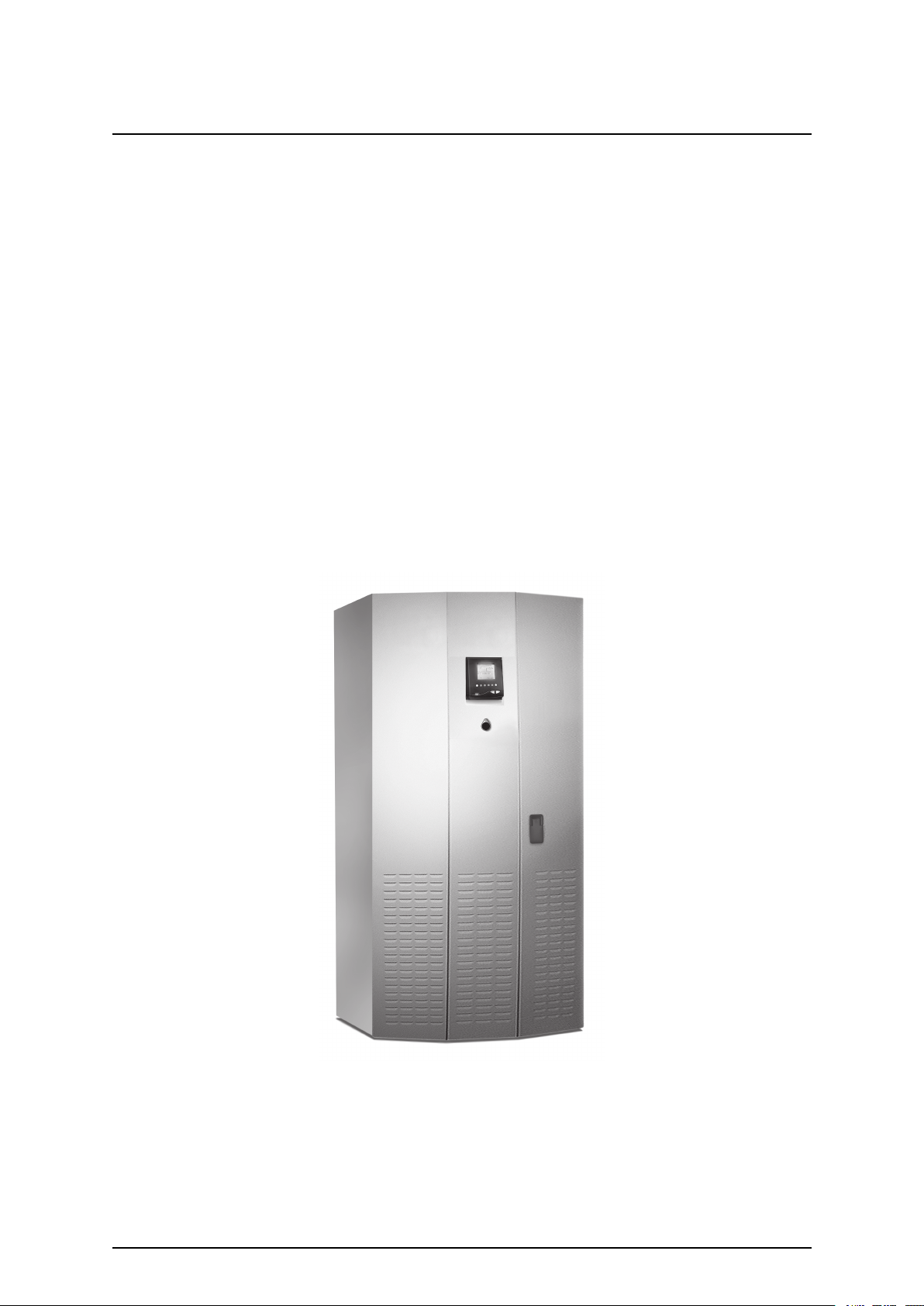
GeneralDescription
TheMGEGalaxy4000istheworld’srstdatacentergradeUninterruptiblePowerSupplysystem
designedspecicallyformid-rangeenterpriselevelapplications.TheMGEGalaxy4000family
consistsofunitsavailableinpowerratingsfrom40-75KV A,andareoptimizedforcompatibilitywith
nonlinearcomputer-typeloads.
ByincorporatingtheUltraHighAvailabilityT opology(UHAT),theMGEGalaxy4000familyofUPS
systemsaredesignedtoprovidetheoptimallevelofreliabilityandtoreacttoanypowerdisturbance
inaninherentlysafewaytoprotectthecriticalload.TheMGEGalaxy4000all-in-onedesign
incorporateseveryfeatureintoonecompactcabinet,includingagraphicaluserinterface,powerfactor
correctedinput,andcommunicationcardsthatsupportnetworkbasedpowermanagement.
TheMGEGalaxy4000UPSanditsauxiliaryequipmentaredesignedforinstallationinaroomwhere
humidityandtemperaturecanbecontrolled.
TheMGEGalaxy4000UPSandauxiliaryequipmentislistedforsafetybyUnderwritersLaboratories,
Inc.(UL)underULStandard1778–UninterruptiblePowerSystems;andalsolistedbyUnderwriters
Laboratories(CUL)underCanadianStandardsAssociation(CSA)standardC22.107.
4
MGEGalaxy400040–75kV A208V
990–3964–001
Page 9

MajorComponents
RectierConvertsACinputvoltagetoDCvoltage.TherectierusesIGBT(Insulated
GateBipolarTransistor)powertransistorsandaPulseWidthModulated(PWM)
techniquetoprovideinputpowerfactorcorrectionandtominimizeanyharmonic
reectedontotheinputpowerlines.
Inverter
StaticSwitchAutomaticallysuppliestheattachedloadfromthebypasssourcewhentheinverter
BatterySystem
SingleLineDiagram
Duringnormaloperation,theutilitypower(Maininput)issuppliedtotheUPSrectier.Therectier
convertstheACpowertoDCthatissuppliedtotheinverter.TheinverterconvertstheDCvoltageto
three-phaseregulatedACvoltage,whichissuppliedtotheattachedload.
Duringpowerfailureconditions,theinverterissuppliedbythestoredenergyinthebatterysystem,and
theloadispoweredcontinuouslywithnointerruption.
ConvertsDCvoltagefromtherectierorfromthebatteriesintoACoutputvoltage
tomaintaintheattachedload.ThismoduleusestheIGBTtechnologytoprovide
digitalpowerquality.
isoff.
Storesenergyforutilizationbytheinverterandattachedloadintheeventthatutility
ACpowerislostorisofunacceptablequality.
TheMGEGalaxy4000UPSisdesignedforinternaloperationof208V ACinputandoutput.External
batteries,andanoutputdistributionpanelmaybecontainedinauxiliarycabinetssimilarindesignto
theMGEGalaxy4000cabinet.Batteriesorexternalmaintenancebypasscircuitbreakersmayalsobe
containedinthirdpartycabinetsorwallmountedunits.
RefertoAppendix“SingleLineDiagram”.
StandardCabinets
TheMGEGalaxy4000individualcabinetdimensionsare:
•UPScabinet:72.1in(1831mm)Hx33.5in(851mm)Wx35.6in(904mm)D.
•Externalbatterycabinet:72.1in(1831mm)Hx26.5in(673mm)Wx33.5in(851mm)DOR–
•Externalbatterycabinet:72.1in(1831mm)Hx33.5in(851mm)Wx33.5in(851mm)D.
•Distributioncabinet:72.1in(1831mm)Hx19.5in(495mm)Wx33.5in(851mm)D.
TheUPScabinetisdesignedtoprovidefortopandbottomentryoftheutilitypowerfeed.Anoutput
voltageof208V ACisstandardwiththeMGEGalaxy4000anddoesnotrequireanyadditional
cabinetry.ThecompletelistofadditionalcabinetsthatcouldbeincludedwithyourMGEGalaxy4000
systemare:externalmaintenancebypasswallcabinet,externalbatterycabinet,anddistributioncabinet.
Theexternalbatterycabinetsareprovidedintwodifferentcabinetsizesdependinguponthebatterytype
selected.Uptofourbatterycabinetsmaybeprovided.Thecabinetsmaybeinstalledadjacenttothe
UPSorremotelyandaredesignedfortopandbottomentry.Thedistributioncabinetprovidesa42pole
panelboard,withanoptionalsubmaincircuitbreaker.Thecabinetisdesignedfortopandbottomentry.
990–3964–001
MGEGalaxy400040–75kV A208V
5
Page 10

PreparationforOperation
SeveralitemsmustbeconsideredwhenpreparingtheMGEGalaxy4000UPSsystemforoperation.
1.TheUPScabinetanditsauxiliarycabinetsmustbearrangedintherequiredcongurationto
insurethattheinterconnectioncablesarelocatedinthecorrectadjacentcabinets.
2.Thecabinetsmustbeinalocationthatprovidesforproperairowandheatrejection.
3.TheroominwhichtheMGEGalaxy4000UPSsystemislocatedmustmaintainenvironmental
conditionswithinrecommendedtolerances.
4.Allelectricalconnectionsmustutilizethetoporbottomconduitentriesprovided.
Thefollowingsectionsdiscusstheseitemsinmoredetail.
CabinetPlacement
ThecompleteUPSsystemmayconsistofonetothreecabinetsdependingontheoptionsselected.The
UPScabinetallowssystemoptionstobeselectedbasedontheapplication.WhenfacingtheMGE
Galaxy4000UPSfromthefront,thestandardarrangementprovidesforanyexternalbatteriestobe
locatedontherighthandside,andthedistributioncabinettobelocatedonthelefthandsideoftheUPS.
A
Airexhaust
B
Displaypanel
C
Allow36”topclearanceforfanexhaustand
servicemaintenance
D
Levelingjacks
E
Casters
6
F
Externalbatterycabinet(optional)
G
UPScabinet
MGEGalaxy4000
H
Frontview
I
Distributioncabinet(optional)
J
Airintake
MGEGalaxy400040–75kV A208V
990–3964–001
Page 11

HeatRejection
TheMGEGalaxy4000UPScabinetsgenerateheatandexhaustairthroughthetopportionofits
enclosures.Airintakeisthroughthebottomandfrontofthecabinet.Allothercabinetsareconvection
cooled.ToassistyouinplanningforyourHV ACneeds,heatrejectiondataisprovidedintablebelow.
Thecabinetairowandrecommendedtopclearanceareprovidedin“CabinetPlacement“section.
TheMGEGalaxy4000isintendedforuseinanenvironmentwherecontroloftemperatureand
humidityisprovided.
HeatRejectionData@208/208V AC
UPSCabinet40kV A50kV A65kV A75kV A
BTU/Hr14,90018,70024,20028,000
Note:Toprovideforadequateventilation,aminimumof36inchesclearanceshouldbe
maintainedabovethetopoftheMGEGalaxy4000cabinet.
CabinetClearances
TheMGEGalaxy4000UPScabinettopclearanceof36inchesforfanexhaustisrecommended.
Additionally,adequatespacemustbeincludedinthefrontandtopofeachcabinet(approx.36inches)
toallowthedoors/panelsofthecabinettobeopenedforserviceandmaintenanceprocedures.
Foraninstallationwhereseismicrequirementsmustbemet,additionalclearanceatthesideofthe
cabinetmustbeincludedtoaccommodatetheseismicanchors.ContacttheCustomerSupportCenter
toorder.
PreparationforStorage
Iftheequipmentistobestoredpriortoinstallation,itshouldbestoredinacool,dry,well-ventilated
locationthatisprotectedagainstrain,splashingwater,chemicalagents,etc.Theequipmentshould
becoveredwithatarpaulinorplasticwrappertoprotectitagainstdust,dirt,paint,orotherforeign
materials.Seethesectionofthismanualtitled"EnvironmentalRecommendations"forrecommended
storageenvironmentalconditions.
Note:Batteriesshouldbestorednolongerthanthree(3)monthsat25°C(77°F)orlower
priortorecharging.Exceedingtherecommendedambientstoragetemperaturewill
reducebatteryback-uptimeandmayadverselyaffectbatterylife.
990–3964–001
MGEGalaxy400040–75kV A208V
7
Page 12

PreparetheInstallation
ConduitPlateLocationsforBottomEntry
CableentrythroughthebottomisthestandardpreferreddesignfortheMGEGalaxy4000UPS
cabinet.Thebottomentryconduitplateprovidesspaceforuptove(5)separateconduitentries.The
plateissecuredwithscrewswhichshouldberetainedfortheconduitplateafterthepowerconnections
aremade.Seeillustrationbelowforthelocationofthebottomentryconduitplates.
A
B
C
Cableentryplate
Airintake
Donotblock
Seismicbracket(optional)(4PLCS)
8
MGEGalaxy400040–75kV A208V
990–3964–001
Page 13

ConduitPlateLocationsforTopEntry
TheUPScabinetfortheMGEGalaxy4000iscapableofacceptingpowerinputandoutputcables
throughatopentry.Theconduitplateonthetopofthecabinetprovidesprovisionsforknockoutsfor
conduitandissecuredtothecabinetwithscrews.
A
B
C
D
10x20.5conduit
Airexhaust
Donotblock
26Wbattery
(33Wbattery)
9x20.5conduit
E
F
G
UPS
Distribution
(16)x1.125K.O.
(34).857K.O
990–3964–001
MGEGalaxy400040–75kV A208V
9
Page 14

ConnectACInputandPowerCables
InstallationSteps
APCrecommendscorrectinstallationvericationandunitstartuptobeperformedbyanAPC
certiedServicepartner .
Caution:SchedulingoftheAPCcertiedServicepartnertypicallyshouldbedone
7to10daysbeforetheyarerequiredon-site.IfthestartupoftheUPSiscriticalto
maintainingyourschedule,pleasecontacttheCustomerSupportCenterforassistance.
Toinsureasuccessfulinstallation,eachofthese(5)stepsshouldbefollowedintheircorrect
sequence.NotethatanyunauthorizedinstallationmaycausedamagetotheUPS(s).
Firststepsbyanon-sitequaliedTechnicalEngineer
1.Unpackandpositiontheunit.
2.Connectthemain(utility)power.
3.Connecttheoutputtotheload.
FinalstepsbyanAPCcertiedServicepartner
4.CallAPCandwaitfortheAPCcertiedServicepartnertoapprovetheinstallation.
5.TheAPCcertiedServicepartnernalizestheinstallationandthestartupprocess.
ElectricalConnections
Caution:Onlyanauthorizedelectricalprofessionalshouldaccesselectricalconnections.
Asevereshockhazardexists.
TheONLYuserserviceableitemsintheMGEGalaxy4000unitare:
A
B
C
D
Themainandbypasspowerconnections.
Theloadconnection.
Anycableconnectiontoexternalorauxiliarymodules.
Thecommunicationcardoptions.
Theaccessmethodforconnectionsmadetothecommunicationcardsisclearlyseenwhenthefront
rightdoortotheMGEGalaxy4000unitisopened.However,accesstothemain,bypassandload
connectionsismadethroughtheremovalofthesafetypanellocatedinthelowerrightoftheMGE
Galaxy4000(withtherightdooropen).Thissafetypanelisremovedbyrstremovingthescrews
securingthepanel.Itcanthenberemovedbyliftingthesafetypanelawayfromtheunit.
Caution:Beforemakinganyelectricalconnections,verifythatallbatterydisconnect
circuitbreakers(QF1)areinthe"off"position.Customer-suppliedupstreamprotective
devicesanddistributioncircuitsshouldbeOFF .
10
MGEGalaxy400040–75kV A208V
990–3964–001
Page 15

TypicalPowerConnections
A
BReararea
C
D
E
F
G
H
I
J
KBX
L
M
Frontview
FrontP
TB4QA
TB1
TB2SC
Ground
Neutral
Negative
Positive
Busbars
TB4Control
A
C
A
NB
OC
RB
T
U
V
W
Y
Z
OutputTB2
TB3Bypassinput
TB1Maininput
Ground
Neutral
BatteryPositive
BatteryNegative
Busbars
990–3964–001
MGEGalaxy400040–75kV A208V
11
Page 16

UPSConnections
Electricalconnectionsandcabinetinterconnectionwillvarydependinguponthecongurationand
optionsselectedwithyourMGEGalaxy4000UPSsystem.Refertotheinstallationdrawingssupplied
withyourequipment.
ConnectingPowerCableConnections:
Toaccesstheconnectionterminalblocks,opentherightdoortotheMGEGalaxy4000UPS.Remove
thesafetypanellocatedinthelowerrighthandsectionoftheunit.See“TypicalPowerConnections“.
1.Thegroundandneutralconductorsmustbeconnectedtothegroundandneutralbusbars,
respectively.Theinputandoutputneutralareconnectedattheneutralbusbar.
2.ConnectthethreeconductorsofthemainACsourcetoterminalblockTB1.
3.Ifbypasssourceispresent,connecttheconductorsofthebypassACsourcetoterminalblock
TB3.Ifbypasssourceisnotpresent,verifyjumpersinplacebetweenTB1andTB3.
4.ConnectthethreeconductorssupplyingtheloadtoterminalblockTB2.
5.Connectthebatteryconductorstothepositiveandnegativebusbars.
6.Secureallcableswithcableties.
7.Putallpanelsandcoversbackinplace.
MainACInputConnections
Theconnectionstobemadearethethreephases,neutral,andgroundcablesfromtheutilityACpower
sourcetotheUPS.ThemainACinputcablesareterminatedatthemaininputterminalblock(TB1).
See“TypicalPowerConnections“.
Note:Forsingleinput(optionalconguration),jumpercablesareprovidedfrom
terminalblocksTB1toTB3.
BypassACInputConnections(optional)
ThebypassACinputcablesareterminatedatthebypassinputterminalblock(TB3).Thisoption
providesaseparateACinputsourceforbypassoperation.See“TypicalPowerConnections“.
12
MGEGalaxy400040–75kV A208V
990–3964–001
Page 17

ConnectBatteryCables
BatteryConnections
Theconnectionstobemadearethepositive,negative,andgroundcablesfromthebatterycabinetto
theUPS.Thebatterycablesareterminatedatthepositive,negative,andgroundbusbars.See“Typical
PowerConnections“.
BatteryControlConnections
Thebatterycontrolconnectionsaremadewiththebatterycontrolcablesfromtheexternalbattery
cabinettotheUPSterminalblockTB4-1toTB4-4.See“TypicalPowerConnections“.
990–3964–001
MGEGalaxy400040–75kV A208V
13
Page 18

ConnectACOutput
ACOutputConnections
Theconnectionstobemadearethethreephases,neutral,andgroundcablesfromtheloadtothe
UPS.Theoutputcablesareterminatedattheoutputterminalblock(TB2).See“TypicalPower
Connections“.
ExternalMaintenanceBypassControlConnections (optional)
Theexternalmaintenancebypass(MBP)controlconnectionsaremadewiththeMBPcontrol
cablefromtheexternalMBPtotheUPSterminalblockTB4-9toTB4-10.See“TypicalPower
Connections“.
WARNING:ThesewirescarryHIGHVOL TAGE120V AC.
AccessoriesOutlets
The120V ACoutletstobeusedonAPCauthorizedaccessoriesonly .Theoutletstotalcurrentnotto
exceed2amps.
Caution:ImproperuseofoutletsmaycausefailureordamagetoUPS.
14
MGEGalaxy400040–75kV A208V
990–3964–001
Page 19

ConnectRemoteEmergencyPowerOff
RemoteEmergencyPowerOffConnections
ThecontrolconnectionsareavailableforRemoteEmergencyPowerOff(REPO)througha
customer-supplied(normallyclosed)pushbutton.WithREPOconnected,thejumperontheREPO
terminalblocksmustberemoved.See“TypicalPowerConnections“.
A.RemovethejumperfromterminalblockTB4locatedacrossterminals7and8.
B.ConnecttheremoteemergencypoweroffNCcontacttoterminals7and8.
Caution:TheUPSisalsoequippedwithalocalEmergencyPowerOff(EPO)buttonon
thefrontoftheUPScabinet.ThisswitchesallUPScriticalpoweroff.EPOorREPO
shouldbeusedforemergencyonly!
990–3964–001
MGEGalaxy400040–75kV A208V
15
Page 20

ConnectRelayCommunicationCard
RelayCommunicationCardContacts
Therelaycommunicationcardcontainssixprogrammabledrycontactoutputsandtwoprogrammable
dryinputsandisstandardontheMGEGalaxy4000.Theinputsandoutputsarefactoryprogrammed
accordingtofunctionslistedintablebelow.
Inputs
1.AUPSON
1.BUPSOFF
OutputsFactorySettings
1.1
1.2
1.3
1.4
1.5
1.6
FactorySettings
Generalalarm
Batteryfault
LoadonUPS
Loadonautomatic
bypass
Loadonbatterypower
Lowbatterywarning
Options(availableonbothcontacts)
•Roomtemperaturefault
•Transfertobypassdisabled
•TransfertobypassdisabledifbypassACsourceoutof
tolerance
•DesynchronizeUPSfrombypassACsource
Options(availableonallcontacts)
•Overload
•PFCFault
•Inverterfault
•Chargerfault
•Automaticbypassfault
•BypassACsourceoutoftolerance
•Battery-temperaturefault
•Emergencypoweroffactivated
•Batterycircuitbreaker(s)open
•Phase-sequencefaultonnormalorbypass
•ACsource
•Blownfuse(s)
•TransfertobypassACsourcedisabled
•OperationinECOmode
•UPSonbypassACsource
Theoutputcontactsnumbersforasecondrelayboardinstalledwillbe2.1to2.6.Contactsareof
theNO(normallyopen)type.Fordrycontactssettingsee“MGEGalaxy400040–75kVA208V
OperationManual—UserConguration—SettingsScreen“.
Caution:Isolateandlock-outallpowersourcesforthiscardbeforemakingconnections.
NeverconnectELSV(extralowsafetyvoltage)andnon-ELSVcircuitstothedifferent
outputsofthesamecard.
16
MGEGalaxy400040–75kV A208V
990–3964–001
Page 21

1
2
3
4
5
6
A
B
1
2
3
4
5
6
A
B
1
2
2
3
4
6
5
5
4
3
1
2
2
7
6
7
990–3964–001
MGEGalaxy400040–75kV A208V
17
Page 22

RelayCommunicationCardConnections
Referto“RelayCommunicationCardContacts“forrelaycommunicationcard,coverandhardware
details.See“MGEGalaxy400040–75kVA208VOperationManual—Operation—Preparingfor
Startup“forcommunicationcardportlocationintheunit.
1.Removethecover“3”securedbythescrews“1”.
2.Runthecommunicationcablesthroughthecableentryholes“4”.
3.Connecttheconductorstotheinput“6”andoutput“5”terminalblocks(referto“Relay
CommunicationCardContacts“foraconnectionexample.)
4.Putthecoverbackinplaceandsecureitwiththescrews“1”.
5.Tightenthescrews“7”toclampthecables.
6.Indicatethelocationsofthepowersourcesonthelabels.
7.Insertthecardinitsslot.
8.Securethecardwithtwoscrews“2”.
CharacteristicsofOutputContacts
RelayTypeNormallyOpen
Max.voltage
Max.current
Cable
250V AC,30VDC
2A
4x0.93mm,6.6±0.3mm
CharacteristicsofInputContacts
Switchedvoltage
Consumption
Cable
Outputalarmsarealwaysactivatedontheconditionsstatedunlessrequestedbycustomertooperateon
otherconditions.
InputcontactsaredesignedforremoteUPSoperation.Useextremecautionwhenusingthesecontacts
soasnottoendangerpersonsorcompromisetheUPSload.
5VDC
10mA
4x0.34mm,5±0.5mm
18
MGEGalaxy400040–75kV A208V
990–3964–001
Page 23

AppendixSingleLineDiagram
AUPS
BBatteryN
C
D
E
F
G
H
I
J
K
L
Distribution
SuppliedbyMGE&Connected
bycustomer
Tocriticalload
42PolePanelboard
Output(optional)
Output
(optional)
(optional)
BypassStaticSwitch
BypassInputTB3
M
O
PInputFuses
Q
R
S
T
U
V
W
MainInputTB1
OptionalBypassInput208YV AC
MainInput280YV AC
InputStaticSwitch
PFCBoostRectier
Inverter
OutputStaticSwitch
BatteryStaticSwitch
BatteryCharger
SuppliedbyMGE&Connectedbycustomer(adjacent
version)
Supplied&connectedbycustomer(standaloneversion)
990–3964–001
MGEGalaxy400040–75kV A208V
19
Page 24

WorldwideCustomerSupport
Customersupportforthisoranyotherproductisavailableatnocharge:
•ContacttheCustomerSupportCenterbytelephoneore-mail.Forlocal,country-speciccenters:
gotowww.apc.com/support/contactforcontactinformation.
©APCbySchneiderElectric.APCandtheAPClogoareownedbySchneiderElectricIndustries
S.A.S.,AmericanPowerConversionCorporation,ortheirafliatedcompanies.Allothertrademarks
arepropertyoftheirrespectiveowners.
990–3964–001
December
2010
 Loading...