

Page 1
Back-UPS® Pro 1000 Installation and
Operation
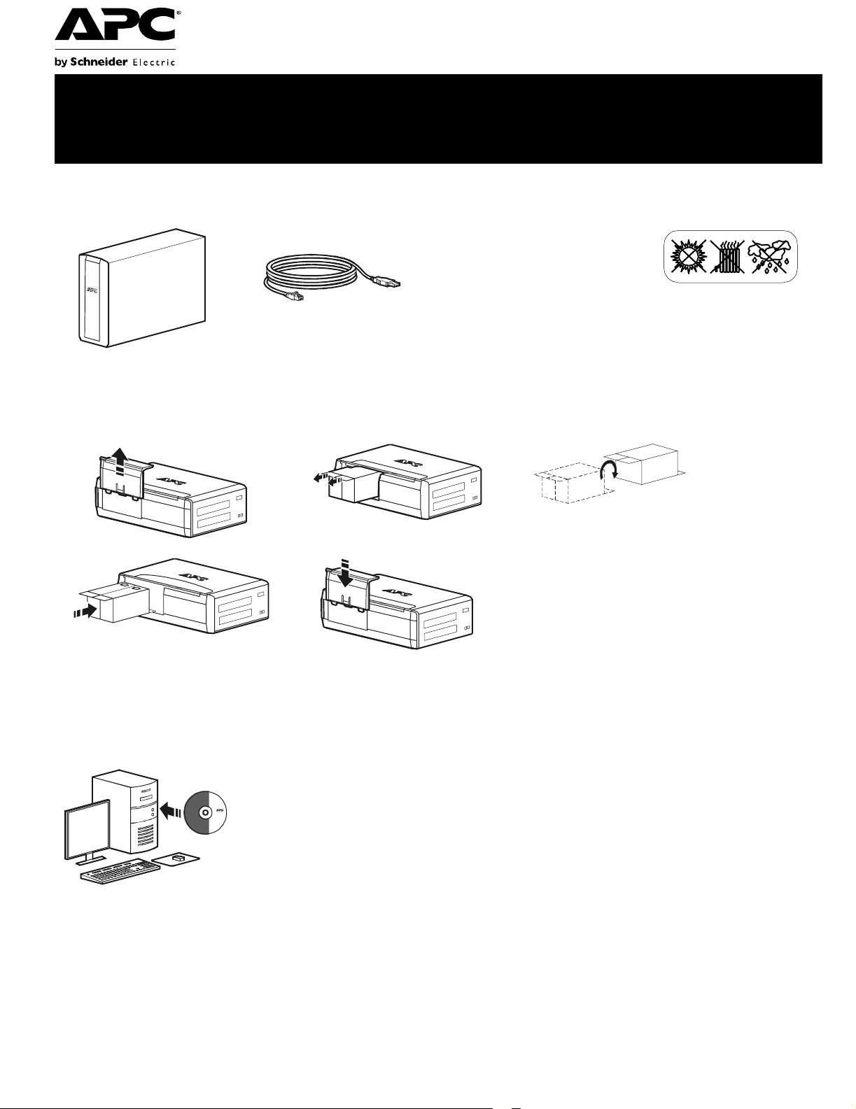
Inventory Safety
Do not install the Back-UPS in direct
sunlight, in excessive heat,
humidity, or in contact with fluids.
bu001b
Connect the battery
bu059a
bu057a
bu055a
bu058a
bu060a
®
Install PowerChute
APC PowerChute Personal Edition sof tware provides automatic file saving and shutdown of
your computer in the event of a power failure. Use the cable supplied with the Back-UPS to
connect the data port on the Back-UPS to the USB port on your computer. Place the CD into
your computer, and follow the on-screen instructions.
Personal Edition Software
Page 2
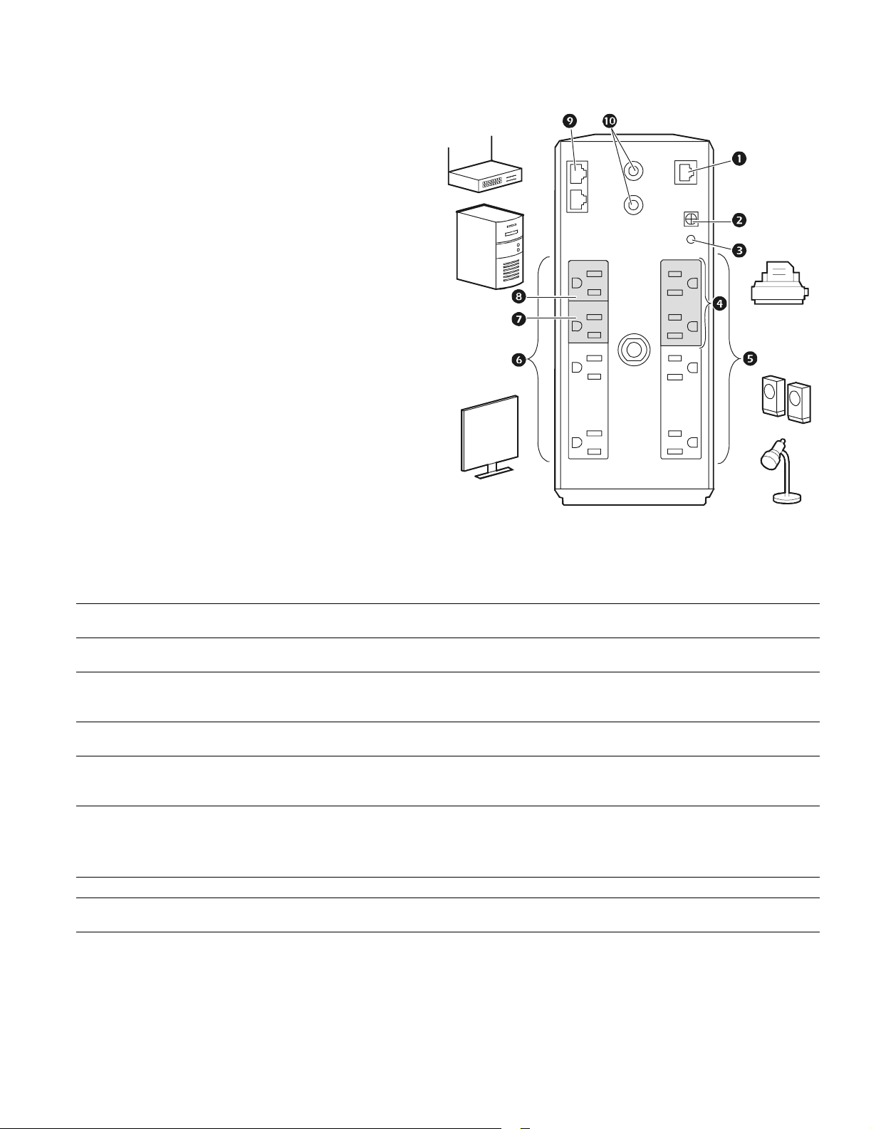
Connect the equipment
Battery Backup and Surge Protected outlets
When the Back-UPS is receiving input power, the
Battery Backup with Surge Protection outlets will
supply power to connected equipment. During a
power outage or other utility probl ems, the Batte ry
Backup outlets receive power for a limited time from
the Back-UPS.
Connect equipment such as printers, fax machines,
scanners, or other peripherals that do not need battery
backup power to the Surge Protect ion Only outlets.
These outlets provi de full-time prot ection from sur ges
even if the Back -UP S i s sw itche d OFF.
Master and Controlled outlets
T o conserve electricity, when the devic e connected to
Master Outlet goes into Sleep or Sta ndby mode, or
turns Off, the Controlled device(s) will shut down as
well, saving electricity.
Connect a master device, such as a des ktop computer
or audio/visual rec eiver to the Master outlet. Connec t
peripheral devices such as a printer, speakers, or a
scanner to the Controlled outlets.
bu126a
USB and Serial Data port To use PowerChute Personal Edit ion, connect the supplied USB software cabl e or ser ial cable
Ground screw Connect the ground lead of additi onal s urge supp res sion devi ces suc h as n etwork an d dat a line
Building Wiring Fault
indicator
Surge Protected outlets,
controlled by the Master
outlet
Surge Protected outlets These outlets provide full-time protection from surges, even if the Back-UPS is off. Connect
Battery Backup outlets with
Surge Protection
Battery Backup outlets with
Surge Protection, contr olled
by the Master outlet
Master outlet Connect the master device to this outlet, in most scenarios , this will be the main computer.
In & Out Ethernet surge-
protected ports
Co-axial ports w ith surge
protection
(available separately).
surge protectors.
If this indicator is il luminated, there is a problem with the wiring in the building. Contact an
electrician immedi ately and do not use the Back-UPS.
These outlets are protected from electr ical surges, and will disconnect from utility power during
a power outage, or if the Mast er device goes into Sleep or St andby mode.
equipment such as printers and scanners that do not require bat tery backup protection.
During a power out age or other utility problems, the Battery Backup outlets receive power for a
limited time from the Bac k-UPS. Connect critical equipment such as desktop computer,
computer monitor, modem or other data sen sitive devices into these outle ts.
These outlets will supply battery power to the connected equip me nt during a power outage.
Power will be disconnect ed to th ese outlets if the Master device goes into Sleep or Stan dby
mode. Connect equipment such as a computer monitor to these outlets.
Use an Ethernet cable to connect a cable modem to the IN port, and connect a computer to the
O
UT port.
Connect a cable modem or other equipment with coaxial jacks.
Back-UPS Pro 1000 Installation and Operation2
Page 3

Operation
Power-Saving Function
T o conserve electricity, configure the Back-UPS to recognize a Master devic e, such as a desktop
computer or an A/V receiver, and Controlled peripheral devices, such as a printer, speakers, or a scanner.
When the Master device goes into Sleep or Standby mode, or is switched OFF, the Controlled device(s)
will be switched off as well, saving electricity.
Enable the Power-Saving function. Press and hold MUTE and DISPLAY simultaneously for two se conds. The
Back-UPS will beep to indicate that the feature is enabled. The leaf icon on the display will illuminate.
Disable t he Power-Saving function. Press and hold MUTE and DISPLAY simultaneously for two seconds. The
Back-UPS will beep to indicate that the feature is disabled. The leaf icon on the display will darken.
Setting the threshold. The amount of power used by a device in Sleep or Standby mode varies between devices. It
may be necessary to adjust the threshold at which the Master outlet signals the Controlled outlets to shut down.
1. Ensure a master device is connected to the Master outlet. Put that device into Sleep or Standby mode, or turn it
OFF.
2. Press
DISPLAY and MUTE simultaneously and hold for six seconds, until the leaf icon flashes three times and the
Back-UPS beeps three times.
3. The Back-UPS will now recognize the thre shold level of the Master device and save it as the new threshold setting.
Power-Saving Display
The display interface can be configured to be continuously illuminated, or to save energy, it can be configured to
darken after a period of inactivity.
1. Full Tim e Mode: Press and hold
DISPLAY for two seconds. The display will illumina te and the Back-UPS will beep
to confirm the Full-Time mode.
2. Power-Saving Mode: Press a nd hold
DISPLAY for two seconds. The display will darken and the Back -UPS will
beep to confirm the Power-Saving mode. While in Power-Saving Mode, the display will illuminate if a button is
pressed, it then darkens after 60 seconds of no activity.
Unit sensitivity
Adjust the sensitivity of the Back-UPS to control when it will switch to battery power; the higher the sensitivity, the
more often the Back-UPS will switch to batter y power.
1. Ensure the Back-UPS is connected to utility power, but is OFF.
2. Press and hold the POWER button for six seconds. The LOAD CAPACITY bar will flash on and off, indicating that the
Back-UPS is in programming mode.
3. Press
POWER again to rotate through the menu options. Stop at selected sensitivity. The Back-UPS will beep to
confirm the selection.
Generator Sensitivity Default Sensitive Loads
Low sensitivity Medium sensitivity (Default) High sensitivity
Input voltage is extremely low or
78-142 Vac 88-139 Vac 88-136 Vac
high. (Not recom me nded for
computer loads. )
The Back-UPS frequently switches to battery power.
Back-UPS Pro 1000 Installation and O peration
The connected equipment is sensitive to vol tage fluctuations.
3
Page 4
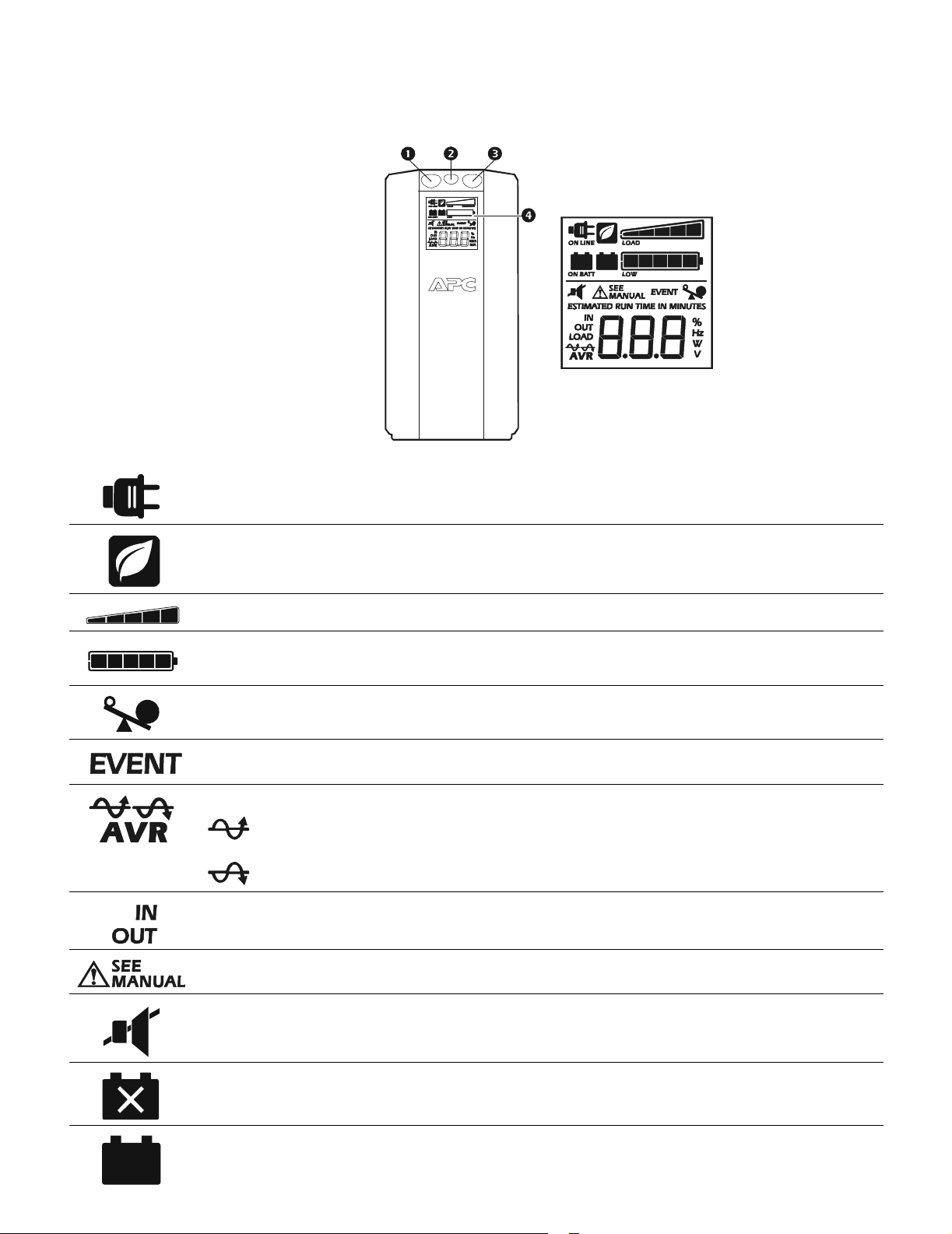
Front Panel Buttons and Display Interface
Use the three buttons on the front panel of the Back-UPS and the display interface to configure the Back-UPS.
Fro nt panel
Mute button
Power On/Off button
Display button
Display interface
bu109a
On Line—The Back-UPS is supplying conditioned utility power to connected equipment
Power-Saving—Master and Co ntrolled outlets are enabled, saving power when the master device goes into
sleep or standby mode
Load Capacity—The load is indicated by the number of sections illuminated, one to five. Each bar represents
20% of the load.
Battery Charge—The battery charge level is indicat ed by the number of sections illuminated. When all five
blocks are illumi nated, the Back-UPS is at full charg e. When one block i s filled, the Back-UPS i s near the end of
its battery capacity, the indicator will flash and the Back-UPS will beep continuously.
Overload—The power demand from the load has exceeded the capacity of the Back-UPS.
Event—The event counter shows the number of events that occur red that caused the Back-UPS to switch to
on-b atter y oper ation .
Automatic Voltage Regulat ion—T he Back-UPS can compensate for high or low input voltage.
When illuminated, th e Back-UPS is compensating for low input voltage.
When illuminated, the Back-UPS is compensating for high input voltage.
In—Input voltage. Out—Output volt age.
System Faults—The system has a fault. The fault number will illuminate on the display int erface. See “System
Faults” on p age5.
Mute—If the line through the speaker ic on is illuminated, the audible al arm has been turned off.
Replace Battery—The battery is not connected or is nearing the end of its useful life. Replace the battery.
On Battery—The Back-UPS is supplying battery backup power to the connected equipment, it will beep four
times every 30 seconds.
Back-UPS Pro 1000 Installation and Operation4
Page 5

Warnings and System Faults
bu0
8
8
a
Audible Warnings
Four Beeps Every 30 Seconds
Continuous Beeping
Continuous tone
Chirps f o r 1 Mi n ut e ev er y 5 hours
Warning Icons
If these icons are
illuminat ed... This may be the problem.
The Back-UPS is operating on utility power, but is overl oaded. Disconnect one of the items
connected to the Back- UPS. If the Overload icon stops flashing, the Back-UPS is no longer
overloaded and will cont inue to operate normally.
The Back-UPS is operating on battery power, but is overl oaded. Disconnect one of the items
connected to the Back- UPS. If the Overload icon stops flashing, the Back-UPS is no longer
overloaded and will cont inue to operate normally.
The Back-UPS is operating on utilit y power, but the battery is not funct ioni ng properl y. Contact APC
Customer Service to order a replacement battery. See “Replacement Battery ” on page 8.
Back-UPS is running on battery. You should consider saving any work in progress.
Low battery conditi on and b attery run- time i s very lo w . Pro mptly sav e any wor k in progress, exit
all open applicati ons, and shut down the operating system.
Battery Backup out puts are overloaded.
Battery fails th e automatic diagnostic test and should be replaced.
The Back-UPS is operating on bat tery power and the battery power is getting low. Shut down all
connected equipment to avoid losing an unsaved data. When pos sible, connect the Back-UPS to
utility power to recharge the batter .
System Faults
The Back-UPS will display these fault messages. For faults F01 and F02, contact APC Technical Support.
On-Battery Overload Turn the Back-UPS off. Disconnect non-essential
F01
On-Battery Output Short Turn the Back-UPS off. Disconnect non-essential
F02
On-Battery Xcap Overload
F03
Clamp Sh o rt
F04
Charge Fault
F05
Relay Welding
F06
Temperature
F07
Fan Fault
F08
Internal Fault
F09
equipment from the Battery Backup outlets and the turn
Back-UPS on.
equipment from the Battery Backup outlets and the turn
Back-UPS on.
Faults F03-F09 cannot be corrected by the user , contact APC Technical Support for assistance.
Back-UPS Pro 1000 Installation and O peration
5
Page 6

Function Button Quick-Reference
Function Button
Power
Power On
Power Off
Display
St atus Inquiry
Full-Time/PowerSaving mode
Mute
Event Specific
General Status Enable/ Disable
Timing
(seconds)
UPS
Status
0.2 Off
2On
0.2 On
2On
0.2 On
2On
Description
Press POWER to start receiv ing input utility power. If A/C input
power is not available, the Back-UPS will run on battery power.
The Back-UPS is not receivi ng input utility power, but is providing surge protection.
Verif y the status or condition of the Back-UPS. The LCD will illuminate for 60 seconds.
The LCD will illuminate and the Back-UPS will beep to confirm the
Full-Time m ode. The LCD will darke n and the Back-UPS will beep
to confirm the Power- Saving mode. While in Power-Savi ng M ode,
the LCD will illuminat e if a butto n is press ed, then darkens af ter 60
seconds of no activity.
Disable any audible alarms caused by an event.
Enable or disable the audi ble ala rms. The Mute i con will ill umina te
and the Back-UPS will beep one time. The Mute function will not
activate unless the Back-UPS is operating on battery power.
Sensitivity
Master/Controlled outlet Enable/Disable
Master/Enable Threshold Calibration
Self-Test (manual )
Event Reset
Fault Reset
6Off
2On
6On
6On
0.2 On
2Fault
The Load Capacity icon will blink, indica tin g th at the B ac k -UP S is
in programming mode. Use the P
Low, Med ium, and High, stop at selected sensiti vity. The BackUPS will beep to confirm select ion. See Configuration for details.
The leaf icon will darken indi cating that the Master Outl et feature is
disabled or illumi nate to indicate the Master Outlet feature is
enabled. The Back-UPS will beep once.
While calibrati ng the threshold setting, the device connect ed to the
Master Outlet should be turned off or placed in Standby or Sleep
mode. Upon completion, Power-Saving icon will flash 3 and beep
3 times.
The Back-UPS will per form a tes t of the i nter nal bat tery. Note: This
will happen automatically when the Back-UPS is turned ON.
When the Event screen is vi sible, press and hold DISPLAY, then
press
After a fault has been iden ti fi ed, press POWER to remove the
visual indicati on and return to standby status.
OWER button to scroll through
POWER, to clear the utility failure event counter.
Back-UPS Pro 1000 Installation and Operation6
Page 7

Troubleshooting
Problem Possible Cause Corrective Action
Back-UPS will not switch on. The Back-UPS is not connected to utility
power.
The circuit brea ker has been tripped. Disconnect non-essential equipment from the
The internal battery is not connected. Connect the battery.
The utility input voltage is out of range. Adjust the transfer voltage and sensitivity range.
The Back-U PS does not
provide power during a utility
power outage.
The Back-UPS is operatin g on
battery power, while connected
to utility power.
The Back-U PS does not
provide the expected amount of
backup time.
The
REPLACE BATTERY
indicator is illuminated.
The O
VERLOAD indicator is
illuminated.
The
SYSTEM FAULT indicator is
illuminated, all the front panel
indicators are flashing.
Power is not supplied to some
outlets.
The Con trol l ed ou tl ets are not
supplying power, even though
the Mast er devi ce is no t in slee p
mode.
Ensur e th at essen t ial equip ment is not
plugged into a
The plug has parti ally pulled out of the wall
outlet, the wall outlet is no longer receiving
utility power, or t he circuit breaker has been
tripped.
The Back-UPS is perf ormi ng an automatic
self test.
The utility input voltage is out of range, the
frequency is out of range, or th e waveform
is distorted.
Battery Backup outlets may be fully or
improperly loaded.
The battery wa s recent ly disc harge d du e to a
power outage and has not fully recharged.
The battery has reached the end of i ts useful
life.
The battery has reached the end of i ts useful
life.
The equipme nt connected to the Back- U PS
is drawi n g mo r e p o w er th an th e B ac k- U PS
can provide.
There is an internal fault . Determine which internal f ault message is
Power to the Controlled outlets has
intentionally been turned off.
The Master Outlet threshold may be
incorrectly set.
SURGE ONLY outlet.
Ensure that the Back-UPS is securely connected
to an AC outlet.
Back-UPS. Rese t the circui t breaker. Re-connect
equipment on e it em at a time . If th e ci r cu i t
breaker is tripped again, disconnect the device
that cau s ed th e tr i p .
Disconnect equi pme nt from the
outlet and re-c onnect to a Battery Backup outlet.
Ensur e that the plug is f ully ins e r ted into th e
wall outle t. Ensure that the wall outlet is
receiving utility power by checking it with
another device.
No action is necessary.
Adjust the transfer voltage and sensitivity range.
Disconnect non-essential equipment from the
Battery Backup outlets and connect the
equipment to
Charge the battery cartridge for 16 hours.
Replace the battery.
Replace the battery.
Disconnect non-essential equipment from the
Battery Backup outlets and connect the
equipment to
displayed by mat ching the number displayed on
the LCD with the corresponding Fault Message
(see System Faults) and contact APC Technical
Support.
Confirm that the correct peripherals are
connected to Controlled ou tlets. If this feature is
not desired, disable the Power-Saving Master
and Controlled outlets.
Adjust the threshold when the Master outlet
signals the Controlled outlets to shut down.
SURGE ONLY outlets.
SURGE ONLY outlets.
SURGE ONLY
Back-UPS Pro 1000 Installation and O peration
7
Page 8

Specifications
t
VA 1000 VA Maximum Load 600 W Nominal Input V oltage 120 V Online Input Voltage Range 88 - 141 V Automatic Voltage Regulation (94-107) +11.2%
(126-141) -11.2% Frequency Range 50/60 Hz ± 1 Hz On-battery Waveshape Step-approximated sine-wave Typical Recharge Time 8 hours Transfer Time 8 ms, maximum Operating Temperature 0 Storage Temperature -5 Unit Dimensions 25 × 10 × 38.2 cm (9.84 × 3.93 × 15.0 in) Unit Weight 10.7 kg (23.6 lbs) Interface USB On-Bat te ry Runtime Go to: ww w.apc .c o m EMI Classification FCC / DOC Class B Certified Approvals TUV C-US, NOM
to 40C (32 to 104F)
to 45C (23 to 113F)
Replacement Battery
The battery cartridge typically lasts 3 to 6 years, a
shorter period if subje cted to frequent outages or
elevated temperat u res. Battery replacement part for
Back-UPS Pro 1000 is APCRBC123. Please recycle
spent battery cartridges.
Service
If the Back-UPS arrived damaged, notify the carrier.
If the Back-UPS requires service, do not return it to the
dealer.
1. Consult the Troubleshooting section to eliminate
common problems.
2. If the problem persists, go to http://www.apc.com/
support/.
3. If the problem still persists, contact APC Technical
Support.
Have the Back-UPS model n u mber, serial number and
date of purchase available. Be prepared to trouble shoot
the problem with an APC Technical Support
representative. If this is not successful, APC will issue a
Return Merchandise
Authorization (RMA) number and a shipping address.
Warranty
The standard w arranty is three (3) years from t h e date of purchase. APC’s standard procedure is to replace the original unit with a factory
reconditioned unit. Custom ers who must have the original unit back due to the assignment of asset tags and set depreciation sch edules must
declare such a need at first contact with an APC Technical Support representative. APC will ship the replacement unit once the defective unit
has been received by the repair department, or cross-ship upon the receipt of a valid credit card number. The customer pays for shipping the
unit to APC. APC pay s ground freight tra nsportation costs to ship the replac em ent unit to the customer
.
APC Worldwide Custom e r Support
Internet http://www.apc.com Worldwide +1 888 272-3858
Customer support and warranty information is available at the APC Web site, www.apc.com.
© 06/2010 Ameri can Power Conversion. All rights reserved. All APC tradema rks are property o f Am erican Power
Conversio n. Other trademarks are property of their respective owners.
990-3804A
6/2010
 Loading...